I. INTRODUCTION
To solve future energy limitations in nonrenewable fuels, it is needed to take the burden off the dependency on fossil fuels. The photocatalytic conversion of CO2 into useful fuels (such as CO, CH4, or CH3OH) is considered one of the most promising strategies to address this crisis. Reference Inoue, Fujishima, Konishi and Honda1–Reference Yuan and Xu5 Since Inoue et al. first reported the photocatalytic reduction of CO2 to hydrocarbon fuels, Reference Inoue, Fujishima, Konishi and Honda1 many research groups had devoted their efforts in developing an efficient photocatalyst. The polymer semiconductor of g-C3N4 has inspired a great deal of interests due to the merits of high stability, moderate band gap, and low cost. Meanwhile, various semiconductors are coupled with g-C3N4 to fabricate heterostructured composite to improve the photocatalytic efficiency. Reference Wen, Xie, Chen and Lia6–Reference Zhao, Zhang, Lin, Nong, Cui, Wu and He10 For example, Ohno et al. reported that the doping of WO3 on g-C3N4 could increase the CH3OH yield by a factor of 2.4. Reference Ohno, Murakami, Koyanagi and Yang11 He et al. used Ag3PO4 to modify g-C3N4, yielding an increased CO2 conversion of 57.5 μmol/(h gcat) which was 6-fold higher than that of naked C3N4. Reference He, Zhang, Teng and Fan12 Zou et al. synthesized g-C3N4/N–TiO2 composite which was proved to be an effective photocatalyst for selective reduction of CO2 to CO. Reference Zhou, Liu, Li, Wang, Jiang, Zhao, Wang, Duan, Liu and Wei13 The similar examples are NaNbO3/g-C3N4, Reference Shi, Chen, Zhang and Zou14 ZnO/g-C3N4, Reference He, Wang, Zhang, Teng and Fan15 and P/g-C3N4. Reference Yuan, Cao, Liao, Yin and Xue16 Among them, Z-scheme-type composite photocatalysts attract much attention due to the special charge-transfer mechanism. Reference Luo, Zhou, Ma and Xu17,Reference Lv, Dai, Zhang, Geng, Liang, Liu, Zhu and Chen18 Take Ag3PO4/g-C3N4 as an example, Reference He, Zhang, Teng and Fan12 the photogenerated electrons in the conduction band (CB) of the Ag3PO4 would annihilate the holes in the valence band (VB) of g-C3N4 via Z-scheme model, leading to the electron in the CB of g-C3N4 and holes in Ag3PO4. On the contrary, if the Ag3PO4/g-C3N4 sample follows type-II mechanism, Reference Shi, Chen, Zhang and Zou14 the photogenerated electron and holes would be enriched on the CB of Ag3PO4 and the VB of g-C3N4, respectively. Given the stronger reducibility and oxidability of the electrons on g-C3N4 and holes on the coupled semiconductor, Z-scheme composites usually present higher photocatalytic activity than the photocatalyst following type-II mechanism, especially for photocatalytic CO2 reduction since the potential of CO2 reduction is more negative than that of H+ reduction. Reference Liu, Hoivik, Wang and Jakobsen2 This analysis indicates that Z-scheme photocatalyst might be an ideal choice for the conversion of CO2 to solar fuels.
MoO3/g-C3N4 composite was reported as an efficient visible-light-driven photocatalyst in degradation of dyes including rhodamine B (RhB), methylene orange (MO), and methylene blue (MB). Reference Huang, Xu, Zhang, Cheng, Xia, Xu and Li19–Reference He, Zhang, Wang, Wu, Lin, Zhao, Weng, Wan and Fan21 It was believed to follow type-II mechanism at first. Reference Huang, Xu, Zhang, Cheng, Xia, Xu and Li19,Reference Li, Huang, Xu, Xu, Xu, Xia and Li20 However, recently, more detailed work indicated that the MoO3/g-C3N4 composite works as a Z-scheme way. Reference He, Zhang, Wang, Wu, Lin, Zhao, Weng, Wan and Fan21 This result suggests that the composite may be efficient in conversion of solar energy to chemical energy, such as photocatalytic CO2 reduction or water splitting. Additionally, two shortcomings are found in the reported MoO3/g-C3N4 composite photocatalyst. One is the preparation method. All the reported MoO3/g-C3N4 was synthesized via mixing-heating method. Reference Huang, Xu, Zhang, Cheng, Xia, Xu and Li19–Reference He, Zhang, Wang, Wu, Lin, Zhao, Weng, Wan and Fan21 In other words, MoO3 and g-C3N4 are prepared first, and then they are mixed and calcined at a moderate temperature. Via this way, the contact between the two semiconductors is usually limited, which would restrict the charge-transfer between them and decrease the separation efficiency of charge carriers. Another one is the low specific surface area. The g-C3N4 applied in the reported MoO3/g-C3N4 is prepared via calcination of melamine, which leads to the low specific surface of the synthesized MoO3/g-C3N4 composite. Both the disadvantages are not beneficial to the photocatalytic process, indicating that there are rooms for improvement of the MoO3/g-C3N4.
On the basis of the above analysis, herein, Z-scheme photocatalyst MoO3/g-C3N4 was prepared via an impregnation method with g-C3N4 and (NH4)6Mo7O24 as raw materials. Pure g-C3N4 was prepared via directly heating urea at 550 °C. The formed gas during the calcination process endows the formed g-C3N4 a large surface area (63 m2/g), which is much larger than g-C3N4 prepared from melamine (11 m2/g). MoO3 was in situ formed on the surface of g-C3N4 at 400 °C, which promotes the adhesion of MoO3 on g-C3N4. Finally, the synthesized MoO3/g-C3N4 was applied in photocatalytic CO2 reduction to fuels for the first time. The photocatalytic activity test indicates that the synthesized sample exhibits good photocatalytic activity in CO2 reduction under simulated sun light. Meanwhile, it shows better photoactivity than the previous MoO3/g-C3N4 in RhB degradation.
II. EXPERIMENTAL SECTION
A. Catalysts preparation
All chemicals were purchased from Beijing Entrepreneur Corp (Beijing, China) and used without further purification. Pure MoO3 was prepared by heating ammonium molybdate (99.0%) at 400 °C for 4 h. Pure g-C3N4 powders were prepared by directly calcining urea (99.0%) at 550 °C for 4 h. The MoO3/g-C3N4 composites were prepared via an impregnation method. Typically, different amounts of ammonium molybdate (NH4)6Mo7O24 were dissolved in 2 mL deionized water, after which, 0.15 g of g-C3N4 was added. The resulting mixture was allowed to keep at room temperature for 4 h. After the water in the solution was evaporated at 60 °C, the obtained solid powders were dried and then calcined at 400 °C for 2 h. Through this method, samples with different MoO3 to g-C3N4 wight ratios (i.e., 1 wt%, 3 wt%, 5 wt%, and 7 wt% MoO3/g-C3N4) were obtained and labeled as 1 wt% MC, 3 wt% MC, 5 wt% MC, and 7 wt% MC, respectively.
B. Characterizations
The specific surface areas were measured on Autosorb-1 (Quantachrome Instruments, Boynton Beach, Florida) by the BET method. The powder X-ray diffraction (XRD; Philips PW3040/60, Philips, Amsterdam, the Netherlands) was used to record the diffraction patterns of photocatalysts employing Cu Kα radiation (40 kV/40 mA). Fourier transform-infrared (FT-IR) spectra of the samples were obtained by a Nicolet Nexus670 FT-IR spectrometer (Thermo Fisher Scientific, Waltham, Massachusetts) with a resolution of 4.0 cm−1, using KBr as the reference sample. A JEM-2010F transmission electron microscope (JEOL USA, Inc., Peabody, Massachusetts) was used to observe the morphology of the catalysts. The XPS measurements were performed with a Quantum 2000 Scanning ESCA Microprobe instrument (Physical Electronics, Eden Prairie, Minnesota) using AlKα. The C1s signal was set in a position of 284.6 eV. The UV-vis diffuse reflectance spectra (DRS) of catalysts were recorded on a UV-vis spectrometer (Lambda900, PerkinElmer, Waltham, Massachusetts) equipped with an integrating sphere. The PL spectra were collected on FLS-920 spectrometer (Edinburgh Instruments Ltd, Livingston, United Kingdom), using a Xe lamp (excitation at 365 nm) as the light source. Electrochemical impedance spectroscopy (EIS) was carried out in the frequency range of 10−1 to 104 Hz at a bias potential of 0 V versus Ag/AgCl.
C. Photocatalytic test
The photocatalytic CO2 reduction was carried out in a stainless-steel reactor with a quartz window on the top of the reactor (Fig. S1). The light source is a 500 W Xe lamp. 20 mg of solid catalyst was placed on a Teflon catalyst holder in the upper region of the reactor. 4 mL water was preinjected into the bottom of the reactor. Prior to the light irradiation, the above system was thoroughly purged by CO2 to remove air in the reactor. During reaction, the pressure of CO2 was kept to be 0.3 MPa and the photoreaction temperature was kept at 80 °C. After light irradiation for 4 h, the gas product was analyzed by a gas chromatograph (GC-950) with an FID and a TCD detector. Only the products of CO, CH4, and CH3OH were detected.
The photocatalytic degradation of RhB solution (20 mg/L) under visible-light was carried out in an outer irradiation-type photoreactor. A spherical Xe lamp (350 W) equipped with a UV cut and an IR cut filters (800 nm > λ > 420 nm) was used as the visible-light source. The catalyst amount is 0.1 g. The concentration of aqueous RhB was determined by measuring its absorbance of the solution at 554 nm using a UV-vis spectrophotometer. Prior to irradiation, the RhB solution containing photocatalysts was kept stirring an hour in the dark to ensure the adsorption–desorption equilibrium. The reactive species trapping experiment was as same as the photodegradation process except the addition of different scavengers into the RhB solution.
III. RESULTS AND DISCUSSION
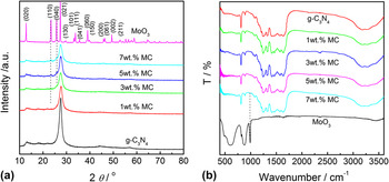
The structure of MoO3/g-C3N4 composite was characterized via XRD and FT-IR. The result of XRD analysis is shown in Fig. 1. One pronounced peak is found in g-C3N4 at 27.4°, which can be assigned to the characteristic interplanar staking peaks of aromatic systems. Reference Xiao, Xie, Cao, Wang and Zhao22 Furthermore, the XRD patterns reveal that the prepared MoO3/g-C3N4 composites consist of MoO3 and g-C3N4 phases except the 1 wt% MC sample [Fig. 1(a)]. For 1 wt% MC sample, only g-C3N4 is observed due to the low content and good dispersal of MoO3. With the increase of MoO3 content, the MoO3 peak intensities increase gradually, while the g-C3N4 peaks weaken. Figure 1(b) shows the FT-IR spectra of MoO3/g-C3N4 composite with different MoO3 concentration. It can be observed that MoO3 presents three strong IR peaks at 996, 562, and 859 cm−1, which can be assigned to the stretching mode of Mo=O and Mo–O–Mo unites, respectively. The FT-IR spectrum of g-C3N4 is more complicated than MoO3. Except the IR signal of out-of plane bending modes of C–N heterocycle at 808 cm−1, several strong IR peaks corresponding to the C=N and aromatic C–N stretching vibration modes are observed in the range of 1200–1600 cm−1. The FT-IR spectra of MoO3/g-C3N4 is nearly as same as that of pure g-C3N4, which can be mainly ascribed to the low content of MoO3 phase. However, for the 7 wt% MC sample, a weak peak at 996 cm−1 corresponding to MoO3 species is observed, confirming the hybrid structure of the MoO3/g-C3N4 composite.
XRD patterns (a) and FT-IR spectra (b) of MoO3/g-C3N4 composites.

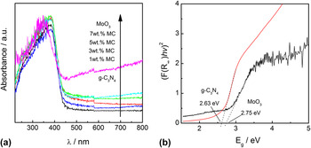
Figure 2(a) shows the UV-vis spectra of MoO3/g-C3N4 composite, as well as g-C3N4 and MoO3 samples. Pure g-C3N4 can absorb the light with wave length lower than 470 nm, corresponding to the band gap of 2.63 eV. For MoO3, the band gap is 2.75 eV [Fig. 2(b)]. Both accord well with the previous results. Reference He, Wang, Zhang, Teng and Fan15,Reference He, Zhang, Wang, Wu, Lin, Zhao, Weng, Wan and Fan21 The similar optical properties of the two semiconductors make the decorating of MoO3 on the g-C3N4 show a little effect on the UV-vis spectra of MoO3/g-C3N4 composites. As shown in Fig. 2(a), the composites with different MoO3 content exhibit nearly the same photoabsorption performance.
UV-vis spectra of MoO3/g-C3N4 composites (a) and the estimated band gaps of g-C3N4 and MoO3 (b).

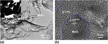
The morphology of MoO3/g-C3N4 hybrid composite was investigated via TEM technique. As shown in Fig. 3(a), the TEM image reveals that MoO3 nanoparticles (20–50 nm) are deposited on the surface of g-C3N4 sheet. In the present work, the ammonium molybdate and g-C3N4 were used as precursors to synthesize MoO3/g-C3N4 composites. During the heating process, the MoO3 particles are in situ formed and attached onto the surface of g-C3N4, thus forming MoO3/g-C3N4 composite. Compared with the pure MoO3 [inset of Fig. 3(a)], the existence of g-C3N4 greatly decreases MoO3 particles size, Reference Yan, Xie, Liu, Cao, Zhang and Luo23 which results in a shorter migration distance of charge carriers and subsequently leads to a higher separation rate. Figure 3(b) shows the high resolution TEM image of MoO3/g-C3N4 composite. A clear lattice fringe of 0.3826 nm is observed in the dark area, which can be assigned to the (110) planes of MoO3. The neighbor area may be the g-C3N4 species since the color of it is lighter than that of MoO3 and no clear lattice fringe is observed. Considering that the sample was ultrasonicated for 10 min before TEM analysis, the result in Fig. 3 indicates that tight contact exists between the in situ formed MoO3 and g-C3N4.
TEM (a) and high resolution TEM (b) images of 3 wt% MoO3/g-C3N4 composite (the inset is pure MoO3).

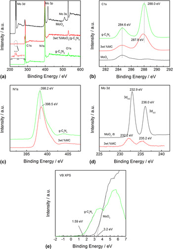
Figure 4 shows the XPS spectra of g-C3N4, MoO3, and 3 wt% MoO3/g-C3N4 composite. All signals of C, N, Mo, and O are detected in the survey XPS spectrum of the MoO3/g-C3N4 composite [Fig. 4(a)], indicating its hybrid structure, which is consistent with the XRD and TEM experiments. Pure g-C3N4 has two C1s signals at 284.6 and 288.0 eV [Fig. 4(b)], corresponding to the adventitious carbon and the sp2-bonded carbon of g-C3N4, Reference Xu, Yan, Xu, Song, Li, Xia, Huang and Wan24 respectively, while MoO3 shows one peak at 294.6 eV. The MoO3/g-C3N4 composite also shows two C1s peaks, indicating its hybrid structure. Meanwhile, a slight shift from 288.0 to 287.8 eV is observed in the C1s peak of 3 wt% MC due to the coupling of MoO3. This kind of effect can also be observed in the N1s and Mo3d XPS spectra [Figs. 4(c) and 4(d)], suggesting the strong interaction between MoO3 and g-C3N4 in the composite, and accords well with the TEM result. Such interaction can benefit the formation of MoO3/g-C3N4 heterojunctions and the smooth charge-transfer between the two semiconductors, which subsequently promotes the separation of electron–hole pairs in the composites. Figure 4(e) shows the VB XPS spectra of g-C3N4 and MoO3. The VB edge of g-C3N4 and MoO3 is determined to be 1.59 and 3.2 eV, respectively, consistent with the previous results. Reference He, Zhang, Teng and Fan12,Reference Shi, Chen, Zhang and Zou14,Reference He, Wang, Zhang, Teng and Fan15
XPS spectra of 3 wt% MoO3/g-C3N4 composite (a) survey spectra; (b) C1s; (c) N1s; (d) Mo3d; (e) valence band XPS.

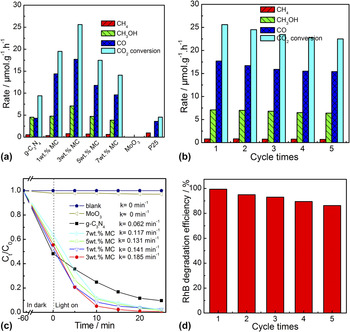
The performance of the MoO3/g-C3N4 composite in photocatalytic CO2 reduction under simulated sunlight irradiation is shown in Fig. 5(a). The blank experiment indicates that both photocatalyst and light irradiation are necessary for photocatalytic CO2 reduction. Methane, methanol, and CO are the detected products, and their distribution is not significantly influenced by the photocatalysts. MoO3 exhibits no photoactivity in CO2 reduction, while g-C3N4 shows a CO2 reduction rate of 9.4 μmol/(h gcat), which is higher than P25 (TiO2). MoO3/g-C3N4 hybrids exhibit much higher photocatalytic activity than pure g-C3N4. With the increase of MoO3 concentration from 1 to 7 wt%, the photocatalytic activity first increases and then decreases. Sample 3 wt% MC exhibits the highest CO2 reduction rate of 25.6 μmol/(h gcat), which is 2.7 times higher than that of g-C3N4. Figure 5(b) shows the cycling run of 3 wt% MoO3/g-C3N4 composite in photocatalytic CO2 reduction under simulated sunlight irradiation. For each run, the sample was dried and then irradiated by a Xe lamp for 4 h. It can be seen that there is a slight decrease in the CO2 reduction rate over the first two cycling runs. After that, rate changes little. So is the products’ distribution. The result in Fig. 5(b) indicates that the synthesized MoO3/g-C3N4 composite is stable in photocatalytic CO2 reduction.
Photocatalytic activities of MoO3/g-C3N4 composite for CO2 reduction (a) and RhB degradation (c), and the cycling run of 3 wt% MoO3/g-C3N4 in CO2 reduction (b) and RhB degradation (d).

In addition to the photocatalytic CO2 reduction, the MoO3/g-C3N4 composite also shows high activity in RhB degradation under visible-light irradiation. As shown in Fig. 5(c), all the MoO3/g-C3N4 composites show worse ability in RhB adsorption than pure g-C3N4. However, the degradation efficiency of the composites is better. The 3 wt% MC sample is still the best photocatalyst. The degradation rate reaches 0.185 min−1, which is nearly three times of pure g-C3N4. Considering that the previous MoO3/g-C3N4 composite which is synthesized via mixing-calcination method (MoO3/g-C3N4–MC) just presented a degradation rate of 004 min−1, Reference He, Zhang, Wang, Wu, Lin, Zhao, Weng, Wan and Fan21 it is no doubt that the in situ decoration of MoO3 on porous g-C3N4 (MoO3/g-C3N4–ID) generates a more efficient photocatalyst. Additionally, the MoO3/g-C3N4–ID sample present good stability in photocatalytic degradation of dye solution. As shown in Fig. 5(d), with the increase of cycling run times, the degradation efficiency decreases slightly. Based on the previous literature, the decrease in activity can be ascribed to the loss of photocatalyst and the dissolution of MoO3 in water solution. Reference He, Zhang, Wang, Wu, Lin, Zhao, Weng, Wan and Fan21 For the fifth cycling run, the degradation efficiency is 86.3%, which reaches 87% of the original photocatalytic activity. However, for the MoO3/g-C3N4–MC composite, only 55% of the initial activity was obtained after four recycling runs. Reference He, Zhang, Wang, Wu, Lin, Zhao, Weng, Wan and Fan21 This result confirms the better stability of MoO3/g-C3N4–ID composite. It may be ascribed to that the in situ decoration method strengthens the contact between MoO3 and g-C3N4, which not only promotes the charge-transfer between the two semiconductors, but also increases the adhesion of MoO3 in the composite. Clearly, the MoO3/g-C3N4–ID composite is a better photocatalyst both in terms of photoactivity and stability.
The surface area of a photocatalyst is usually associated with the activity because a high surface area is required for the satisfactory adsorption of reactant, which benefits the photocatalytic reaction. Hence, the BET surface area of the synthesized MoO3/g-C3N4 was investigated. The N2 adsorption/desorption isotherms exhibit the characteristics of type IV-like isotherm, indicating the mesoporous nature of the pure g-C3N4 and MoO3/g-C3N4 samples (Fig. S2). The deposition of MoO3 on g-C3N4 decreases the specific surface area. The BET values of g-C3N4, 1 wt% MC, 3 wt% MC, 5 wt% MC, and 7 wt% MC are determined to be 63, 55, 51, 52, and 50 m2/g, respectively. This result is consistent in their performance in RhB adsorption [Fig. 5(c)]. However, no correlation consistency between specific surface area and photocatalytic activity is observed, indicating that the specific surface area is not a major factor in affecting the photocatalytic activity. The superior photocatalytic activity of MoO3/g-C3N4 composites should be attributed to the efficient separation of photo-generated carriers in composites, as other g-C3N4 based composites. Reference Adhikari, Pant, Kim, Park and Kim25–Reference Vignesh, Suganthi, Min and Kang31
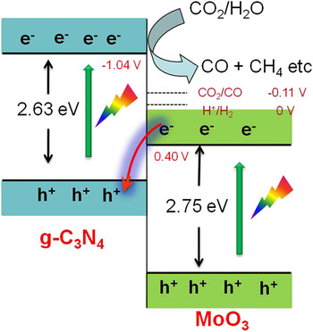
Based on the equation of E
CB = E
VB − E
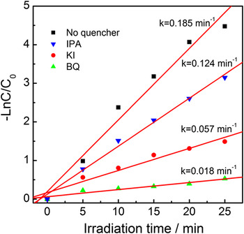
g and the results of VB XPS and DRS, the CB and VB edge potentials of MoO3 are determined to be 0.40 and 3.15 eV, respectively. For g-C3N4, the two values are −1.04 and 1.59 eV. Therefore, the two semiconductors have suitable band potentials to construct a Z-scheme heterojunction structure. Driven by the inner electric field in the composite, the photogenerated electrons on the CB of MoO3 would annihilate the holes on the VB of g-C3N4, leading the accumulation of electron and holes on the CB of g-C3N4 and VB of MoO3, respectively (Fig. 6). It causes an efficient separation of photogenerated electrons and holes to enhance the photocatalytic activity. The radical trapping experiments were performed to prove the Z-scheme mechanism of MoO3/g-C3N4. Figure 7 shows the first-order kinetics plot of the photocatalytic RhB degradation in the presence of 3 wt% MoO3/g-C3N4 composite with three different scavengers, i.e., benzoquinone (BQ, ˙O2
− scavenger), KI (KI, ˙OH and h+ scavenger), and isopropanol (IPA, a quencher of ˙OH).
Reference Li, Wong, Zhang, Hu, Yu, Chan and Wong32,Reference Xu, Shi, Song, Chen, Yang, Fan and Chen33
It can be seen that the order of the retarding effect of the three scavengers is BQ > KI > IPA, indicating the most important reactive species is ˙O2
− species. Considering that the CB bottom of MoO3 is lower than the standard reduction potential of O2/˙O2
−
 $\left( {{E_{{{\rm{O}}_{\rm{2}}}{\rm{/}}{}^ \cdot {{\rm{O}}_2}^ - }} = - 0.046\;{\rm{V}}} \right)$
,
Reference Wang, Kako and Ye34,Reference He, Zhang, Fan, Wang, Walbridge, Nong, Wu and Zhao35
this result indicates that the photogenerated electrons accumulate on the CB of g-C3N4. In other words, the data in Fig. 7 confirms that the migration of photoexcited electron and holes in the MoO3/g-C3N4 composite follows a direct Z-scheme mechanism, just as shown in Fig. 6. The result of photocatalytic CO2 reduction provides another powerful proof. The CB edge of MoO3 is positive than the reduction potential of CO2
 $\left( {{E_{{\rm{C}}{{\rm{O}}_{\rm{2}}}{\rm{/CO}}}} = - 0.11\;{\rm{V}}} \right)$
,
Reference Liu, Hoivik, Wang and Jakobsen2
indicating that the photogenerated electrons cannot reduce CO2 to fuels, as proven in Fig. 5. Therefore, if the MoO3/g-C3N4 composites follow the type-II mechanism, the photogenerated electron would be enriched on the CB of MoO3. In other words, the introduction of MoO3 to g-C3N4 cannot significantly promote CO2 reduction, which is contrary to the experimental result.
Scheme for electron–hole separation and transport at the interface of MoO3/g-C3N4 composite.

The first-order kinetics plot of the photocatalytic RhB degradation in the presence of 3 wt% MoO3/g-C3N4 composite with different scavengers.

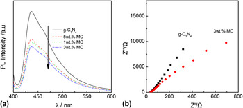
On the basis of the above analysis, it can be deduced that the decoration of MoO3 on g-C3N4 promotes the separation efficiency of charge carriers, and subsequently increases the photocatalytic activity. The PL experiment was thus performed to confirm the inference. In general, a strong PL emission represents fast recombination of electrons and holes. As Fig. 8(a) shows, pure g-C3N4 exhibits a strong emission in the range of 400–550 nm, according well with the previous result. Reference He, Zhang, Teng and Fan12 The addition of MoO3 significantly weakens the PL peak, indicating that the recombination of electron–hole pairs is greatly inhibited. Reference Jo and Selvam36–Reference Tian, Chang, Lu, Fu, Xi and Dong39 Meanwhile, it can be noted that the 3 wt% MC sample presents the weakest PL peak, which is consistent with the data in Fig. 5. In addition to PL analysis, EIS was also performed on g-C3N4 and the 3 wt% MC photoelectrodes to examine the charge-transfer resistance and separation efficiency of the photogenerated electrons and holes. The result shown in Fig. 8(b) indicates that the arc radius of the MoO3/g-C3N4 photoelectrode is smaller than that of pure g-C3N4. This suggests that the MoO3/g-C3N4 composite has lower interface layer resistance than g-C3N4, Reference Lang, Yang, Zhu, Hu, Jiang, Zhong, Gong, Teng, Zhao and Bai40 which can accelerate the interfacial charge-transfer process and subsequently improve the separation efficiency of charge carriers. This result is perfectly consisted with the PL experiment.
PL (a) and EIS spectra (b) of g-C3N4 and MoO3/g-C3N4 composites.

IV. CONCLUSION
MoO3/g-C3N4 composite was prepared via a simple impregnation method. A small amount of MoO3 nanoparticles grown onto g-C3N4 surfaces leads to considerable improvement on the photocatalytic activities for CO2 reduction and RhB degradation, which is ascribed to the improved separation efficiency of electron–hole pairs via a direct Z-scheme mechanism. This study might provide a new insight to address the low photoactivity of pristine g-C3N4 for water purification and CO2 reduction.
Supplementary Material
To view supplementary material for this article, please visit https://doi.org/10.1557/jmr.2017.271.
ACKNOWLEDGMENTS
This work was financially supported by Natural Science Foundation of Zhejiang Province in China (LY16B030002).