I. INTRODUCTION
At nanoscales, residual stresses occur in thin films, thin rolled plates, and the like. These residual stresses lead to such undesired behaviors as film delamination, buckling, and cracking of the component, which cause problems in applications and also affect such mechanical properties as fatigue characteristics.Reference Fu, Du, Huang, Zhang and Hu1,Reference Baragetti, La Vecchia and Terranova2 Indentation testing can evaluate the residual stresses quantitatively and easily, without damaging the object, and is applicable to both crystalline and amorphous materialsReference Jang3,Reference Suresh and Giannakopoulos4 ; hence many studies have been carried out on evaluating residual stress using indentation.
The influence of applied stress on the mechanical properties such as hardness and elastic modulus obtained by nanoindentation was first studied through experiments by Tsui et al.Reference Tsui, Oliver and Pharr5 and using finite element analysis by Bolshakov et al.Reference Bolshakov, Oliver and Pharr6 They investigated the indentation curves and real contact areas and found that, though the indentation curves are dependent on stress, the hardness and elastic modulus calculated from real contact area are independent of stress. Using results from Tsui and Bolshakov, Suresh and GiannakopoulosReference Suresh and Giannakopoulos4 established a theoretical model to determine surface residual stresses and residual plastic strains using instrumented sharp indentation in equibiaxial stress fields, and this model was confirmed by Carlsson and Larsson.Reference Carlsson and Larsson7,Reference Carlsson and Larsson8 And SwadenerReference Swadener, Taljat and Pharr9 developed an experimental technique based on instrumented spherical indentation that evaluates the biaxial residual stress more accurately than the sharp indenter. Lee and KwonReference Lee and Kwon10 did tensor analysis of the stresses beneath a sharp indenter and found that the deviatoric stress component in the z-direction (coincident with the indenting direction) of the residual stress is related to the indentation load difference (ΔL = L 0 − L s) caused by residual stress. The indentation loading curve is shifted according to the stress state of the specimen. Using this relation, they derived the following equations to evaluate the surface biaxial residual stresses,  $\sigma _{{\rm{res}}}^x$ and
 $\sigma _{{\rm{res}}}^y$, using a Vickers indenter and a Berkovich indenter and assuming that the x- and y-axes are the principal directions of the surface residual stresses.
 $$\sigma _{{\rm{res}}}^x = {3 \over {1 + p}}{{\Delta L} \over {{A_{\rm{s}}}}}\quad ,$$
 $$\sigma _{{\rm{res}}}^y = p\sigma _{{\rm{res}}}^x = {{3p} \over {1 + p}}{{\Delta L} \over {{A_{\rm{s}}}}}\quad .$$
In Eqs. (1) and (2), ΔL is L 0 − L s, the indentation load difference between the stress-free state and stressed state at a given indentation depth. A s is the contact area in the stressed state at a given indentation depth and p is the stress directionality which is the ratio of the residual stresses in the x- and y-axes  $\left( {{{\sigma _{{\rm{res}}}^y} \over {\sigma _{{\rm{res}}}^x}} = p} \right)$. To evaluate the stress directionality, p, Lee et al.Reference Lee, Takashima, Higo and Kwon11 observed the pile-up height of the residual imprint after indentation testing in a nonequibiaxial stress state. Lee found the pile-up height depends on the stress state and evaluated the stress directionality using the relation. Han et al.Reference Jae-Hwan Han, Lee, Choi, Lee, Kim and Kwon12 and Choi et al.Reference Choi, Kang, Kang and Kwon13 suggested a model to evaluate stress directionality for nonequibiaxial stress state using a Knoop indenter which has 2-fold rotational symmetry and with a ratio of long diagonal to short diagonal of 7.11:1. Because the Knoop indenter is less axisymmetric than the Vickers and Berkovich indenters, the indentation load difference from the Knoop indenter depends on the direction of long diagonal of the indenter in nonequibiaxial stress states. They introduced conversion factors, α‖ and α⊥ that indicate the correlation between the indentation load difference (ΔL = L 0 − L s) and the residual stress components normal and parallel to the long diagonal of the Knoop indenter. The influence of the residual stresses on the indentation load difference is
 $$\Delta {L_x} = {\alpha _{\parallel} }\sigma _{{\rm{res}}}^x + {\alpha _ \bot }\sigma _{{\rm{res}}}^y\quad ,$$
 $$\Delta {L_y} = {\alpha _ \bot }\sigma _{{\rm{res}}}^x + {\alpha _{\parallel} }\sigma _{{\rm{res}}}^y\quad .$$
They also found that the conversion factor ratio  $\left( {{{{\alpha _{\parallel} }} \over {{\alpha _ \bot }}}} \right)$ remains constant at 0.34 regardless of indentation depth, material properties, and stressed state. Kim et al.Reference Kim, Choi, Kwon and Kim14 expanded this model to estimate the principal direction of residual stress, θP, and its stress directionality. In addition, Ahn et al.Reference Ahn, Kim, Xu, Lee, Kim, Kim and Kwon15 evaluated the stress directionality using a wedge indenter based on the concept of conversion factors and confirmed that the conversion factor ratio of a wedge indenter in which geometrical self-similarity was not maintained depending on the indentation depth.
However, most research on stress directionality has been performed using microindentation and it is difficult to manufacture a nanoscale Knoop indenter that maintains its shape well enough that the four faces join at a point and thus meet ASTM requirements.16 To avoid this limitation, we developed a new indenter by extending a conventional Berkovich indenter in one direction so that we could use nanoindentation to evaluate stress directionality for a nonequibiaxial stress state. We obtained the conversion factors and the conversion factor ratio at different indentation depths for the new indenter and verified it by evaluating the stress directionality for various nonequibiaxial stress states and comparing the results with the applied reference values. In addition, we obtained the conversion factor ratios of the indenters extended at different height-to-base ratios through experiments and finite element analysis. We found that the conversion factor ratio depends on the degree of extension of the conventional Berkovich indenter in one direction, and we generalized this finding to empirical relation using a mathematical approach. In addition to this method, different indentation curves can be obtained in the nonequibiaxial stress state by rotating the Berkovich indenter through tilting of the specimen. Experiments with a Berkovich indenter on a tilted specimen can yield an isometric triangular residual imprint; however, this method leads to the complexity of testing that the specimen should be tilted. Also, because the tilted specimen is not perpendicular to the indenting axis, it should cause instability of the instrument and complicate the test. Therefore, in this study, we introduce a new shape indenter while keeping the indenting axis perpendicular to the specimen surface.
II. MODIFIED BERKOVICH INDENTER
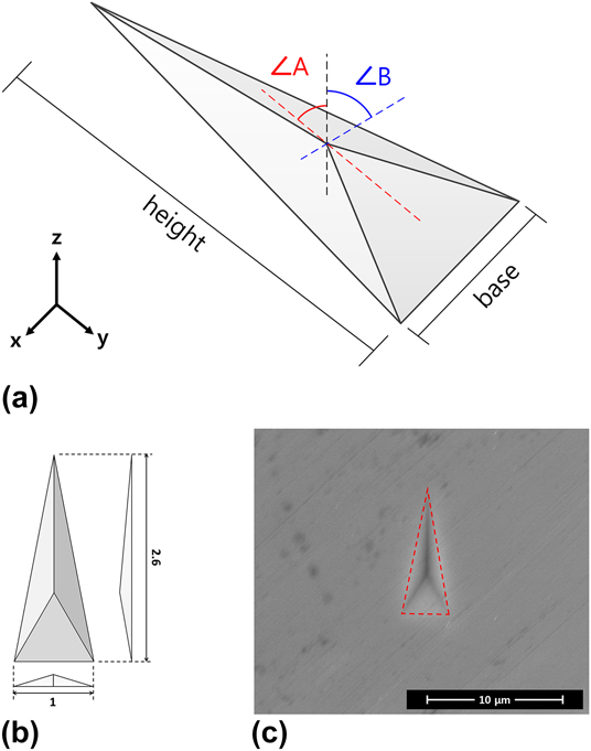
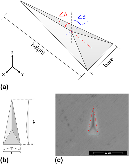
Here we suggest a new indenter for evaluating stress directionality, p, using nanoindentation that meets the following requirements. First, the new indenter should be less axisymmetric than Vickers and Berkovich indenters. In other words, in the plane perpendicular to the indenting axis, the lengths of the two sides of the indenter in the vertical relation must be different so that the indentation load difference changes as the indenter rotates about the indenting axis like the Knoop indenter.Reference Jae-Hwan Han, Lee, Choi, Lee, Kim and Kwon12–Reference Kim, Choi, Kwon and Kim14 Second, to keep the conversion factor ratio  $\left( {{{{\alpha _{\parallel} }} \over {{\alpha _ \bot }}}} \right)$ constant independent of indentation depth, like the Knoop indenter, the new indenter should be sharp and geometrically self-similar (i.e., so that the shape of the residual imprint at each indentation depth is similar). Third, the tip of the proposed indenter should be positioned at the center of gravity when viewed from above so that the stress during indentation testing is evenly distributed on the indenter. We modified a conventional Berkovich indenter to meet these requirements (Fig. 1). Because the conventional Berkovich indenter has three sides, it can attain a sharper tip than traditional four-sided indenters: the three sides join easily at one point.Reference Dukino Rodney and Swain Michael17 We created a new indenter by extending the conventional Berkovich indenter along one axis (the y-direction in Fig. 1) so that its residual imprint is shaped like an isosceles triangle after indentation testing [Fig. 1(c)]. A schematic diagram of the modified Berkovich indenter is shown in Fig. 1(a); the indenters have different height-to-base ratios depending on the degree of extension. Here we considered indenters with height-to-base ratios of 1.7:1, 2.6:1, and 4.3:1 using experiments and finite element analysis. In particular, we made a modified Berkovich indenter with a ratio of 2.6:1 which is the maximum ratio considering the reproducible manufacture of indenter for the experiments. We call it 2.6:1 modified Berkovich indenter, which is designed to satisfy 80.1° for ∠A and 65.3° for ∠B of Fig. 1(a).
(a) Schematic diagram of modified Berkovich indenter, (b) schematic diagram of the 2.6:1 modified Berkovich indenter viewed along the x-, y-, and z-axes, and (c) SEM image of residual imprint of the 2.6:1 modified Berkovich indenter.
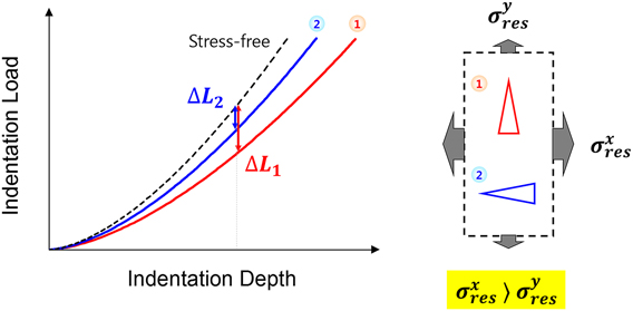
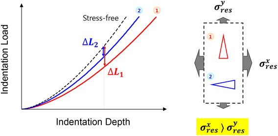
Since this indenter is extended in one direction, the indentation load difference depends on indenter orientation and conversion factors can be introduced as with the Knoop indenter.Reference Jae-Hwan Han, Lee, Choi, Lee, Kim and Kwon12–Reference Kim, Choi, Kwon and Kim14 In this research, it is assumed that the x- and y-axes are the principal directions; Fig. 2 shows how the indentation load difference changes when the indenter’s extended axis coincides with the x- and y-axes, which are the principal direction of the residual stresses when the stress along the x-axis is greater than that along the y-axis.
Schematic indentation loading curves according to the direction of extended axis of the modified Berkovich indenter.
Here, we set the conversion factors for the modified Berkovich indenter to γ‖ and γ⊥. The subscripts indicate the relationship between the stress direction and the extended axis of the modified Berkovich indenter: γ‖ is parallel and γ⊥ is the normal relation. Hence this indenter can be used to evaluate stress directionality in nonequibiaxial residual stress:
 $$\Delta {L_x} = \Delta {L_{\parallel} } + \Delta {L_ \bot } = {\gamma _{\parallel} }\sigma _{{\rm{res}}}^x + {\gamma _ \bot }\sigma _{{\rm{res}}}^y\quad ,$$
 $$\Delta {L_y} = \Delta {L_ \bot } + \Delta {L_{\parallel} } = {\gamma _ \bot }\sigma _{{\rm{res}}}^x + {\gamma _{\parallel} }\sigma _{{\rm{res}}}^y\quad .$$
In Eqs. (5) and (6), ΔL x and ΔL y are the indentation load differences obtained using the indentation loads in the stressed and the stress-free states when the extended axis of the modified Berkovich indenter is along the x- and y-axes. ΔL x and ΔL y are the sum of ΔL ‖ and ΔL ⊥, respectively, where ΔL ‖ and ΔL ⊥ are the load differences due to the residual stresses in each direction parallel and normal to the extended axis of the indenter. The above equations show how the stresses in each direction contribute to the indentation load difference.
To calculate the ratio of residual stresses in the principal directions using the above equations, we express the ratio of ΔL x and ΔL y as
 $${{\Delta {L_x}} \over {\Delta {L_y}}} = {{{\gamma _{\parallel} }\sigma _{{\rm{res}}}^x + {\gamma _ \bot }\sigma _{{\rm{res}}}^y} \over {{\gamma _ \bot }\sigma _{{\rm{res}}}^x + {\gamma _{\parallel} }\sigma _{{\rm{res}}}^y}} = {{{{{\gamma _{\parallel} }} \over {{\gamma _ \bot }}} + {{\sigma _{{\rm{res}}}^y} \over {\sigma _{{\rm{res}}}^x}}} \over {1 + {{{\gamma _{\parallel} }} \over {{\gamma _ \bot }}}{{\sigma _{{\rm{res}}}^y} \over {\sigma _{{\rm{res}}}^x}}}} = {{{{{\gamma _{\parallel} }} \over {{\gamma _ \bot }}} + p} \over {1 + {{{\gamma _{\parallel} }} \over {{\gamma _ \bot }}}p}}\quad .$$
The above equation can be expressed in terms of the stress directionality, p, as follows:
 $$p = {{\sigma _{{\rm{res}}}^y} \over {\sigma _{{\rm{res}}}^x}} = {{{{\Delta {L_x}} \over {\Delta {L_y}}} - {{{\gamma _{\parallel} }} \over {{\gamma _ \bot }}}} \over {1 - {{{\gamma _{\parallel} }} \over {{\gamma _ \bot }}}{{\Delta {L_x}} \over {\Delta {L_y}}}}}\quad .$$
So, the stress directionality, p, can be calculated using the experimental results, the ratio of load differences  $\left( {{{\Delta {L_x}} \over {\Delta {L_y}}}} \right)$, and the conversion factor ratio
 $\left( {{{{\gamma _{\parallel} }} \over {{\gamma _ \bot }}}} \right)$. Because the modified Berkovich indenter is geometrically self-similar, the conversion factor ratio for the modified Berkovich indenter will be constant regardless of indentation depth.
III. EXPERIMENTAL PROCEDURE
The ultra nanoindentation tester (Anton Paar, Switzerland), with load resolution 1 nN and displacement resolution 0.03 nm, and the Nano AIS (Frontics, Inc., Korea), with load resolution 10 nN and displacement resolution 0.04 nm, are used in these experiments. The 2.6:1 modified Berkovich indenter was made by Probes (Korea) for the experiments. This indenter is designed to have a height-to-base ratio of 2.6:1 as shown in Fig. 1(b) and a maximum possible indentation depth of 3 μm.
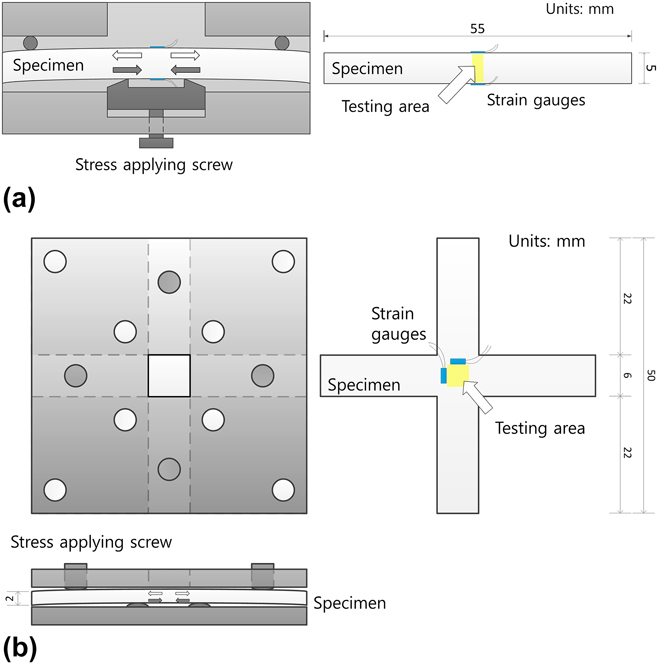
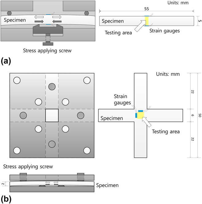
To obtain the conversion factor ratio, various uniaxial tensile stresses are applied to the rectangular specimens (55 × 5 × 8 mm3) using a uniaxial stress-generating jig [Fig. 3(a)].Reference Lee, Ji and Kwon18 We applied stress to the specimens below the elastic limit of the material by considering the yield criterion, and the applied stresses are calculated from the strain values obtained from the strain gauges and the elastic modulus of the material. We obtained load differences for each applied stress by maximum indenting 300, 500, 700, and 900 nm for two materials: S45C and Al6061. After obtaining parallel (γ‖) and normal (γ⊥) conversion factors for each indentation depth, we calculate the conversion factor ratio  $\hbox( {{{{\gamma _{\parallel} }} \over {{\gamma _ \bot }}}} \hbox)$. Mechanical properties and experimental conditions are shown in Table I.
Schematic diagram of (a) uniaxial stress-generating jig and (b) biaxial stress-generating jig.
Mechanical properties & experimental conditions for rectangular specimens.

To verify our model, various nonequibiaxial tensile stress states are applied to the cruciform specimens using a biaxial stress-generating jig [Fig. 3(b)].Reference Lee, Takashima, Higo and Kwon11,Reference Choi, Kang, Kang and Kwon13–Reference Ahn, Kim, Xu, Lee, Kim, Kim and Kwon15 The applied stresses are calculated using the strain gauges and the elastic modulus of the material. Five different nonequibiaxial stress states are applied to the cruciform specimens using 304 austenitic stainless steel, 316 austenitic stainless steel, S45C, C11000, and Al6061 as shown in Table II. The nanoindentation tests are performed five times for each specimen at constant loading rate 20 mN/min to a maximum indentation depth of 1000 nm.
Mechanical properties & experimental conditions for cruciform specimens.

Before applying the stress, all specimens were annealed to relax internal stresses and then polished with 0.25 μm alumina powder. Indentation tests for stress-free and stressed states were performed in the same region in which the homogeneous properties were obtained. Elastic modulus and yield strength are obtained from ultrasonic pulse-echo technique19 and uniaxial tensile testing of the same materials.
In addition, finite element analysis was used to obtain conversion factor ratio for modified Berkovich indenters with different height-to-base ratios, 1.7:1, 2.6:1, and 4.3:1. The 1.7:1 and 4.3:1 modified Berkovich indenters were designed to have ∠B = 65.3°; ∠A was designed to be 75.7° for the 1.7:1 modified Berkovich indenter and 84.0° for the 4.3:1 modified Berkovich indenter [Fig. 1(a)]. Using commercial finite element analysis program ABAQUS 6.12, we simulated indentation tests with the 1.7:1, 2.6:1, and 4.3:1 modified Berkovich indenters and specimens in the stress-free state and uniaxial tensile stressed states. The size of specimens is 10 × 10 × 3 mm3 and they were subjected to uniaxial stresses of 100, 200, and 300 MPa, along the x- and y-axes. The mechanical properties of 303 austenitic stainless steel were used in the calculation: elastic modulus 200 GPa, yield strength 359 MPa, and Poisson’s ratio 0.3. The simulations of the modified Berkovich indenters consist of 67,156 elements of C3D8 mesh-type specimen, 129 elements of R3D4 mesh-type 1.7:1 indenter, 88 elements of R3D4 mesh-type 2.6:1 indenter and 107 elements of R3D4 mesh-type 4.3:1 indenter. Finite element analysis was also used to confirm the pile-up distribution of the 2.6:1 modified Berkovich indenter.
IV. RESULTS AND DISCUSSION
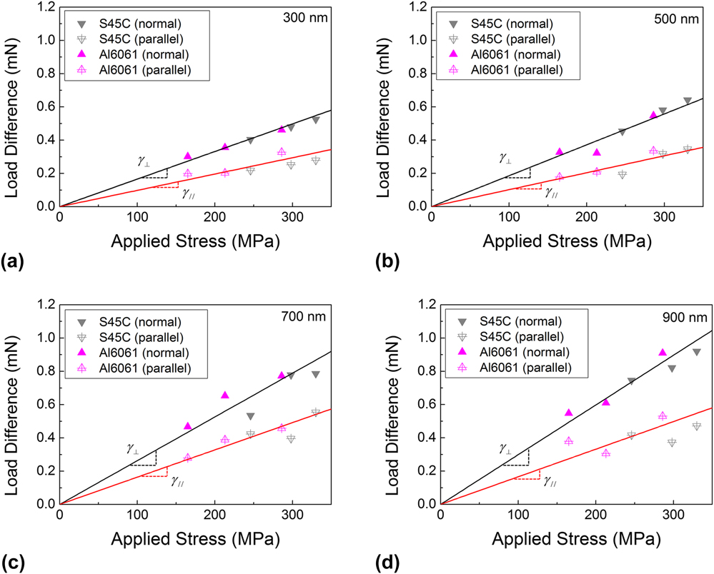
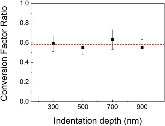
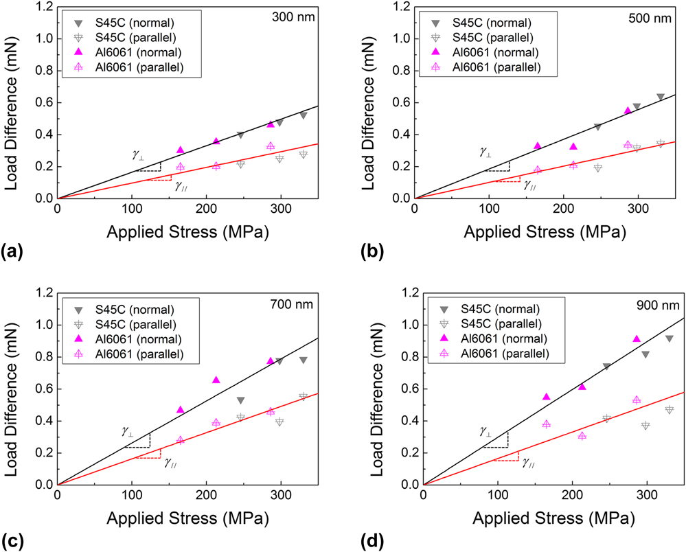
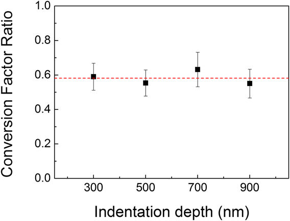
To check that the modified Berkovich indenter senses the indentation load differently depending on the orientation of extended axis, we performed indentation tests by setting the extended axis of the 2.6:1 modified Berkovich indenter parallel and normal to the direction of uniaxial stress. As shown in Fig. 4, the load differences between the stress-free and stressed states are proportional to the applied stress and the slope of the load difference and applied stress depends on the relation between the extended axis of the modified Berkovich indenter and the direction of the uniaxial stress. As with Knoop indentation, under one indentation depth condition, the slope when the extended axis is normal to the stress is greater than the slope when it is parallel. The slopes of Fig. 4 are the conversion factors, and the ratio of the conversion factors corresponding to normal and parallel at each indentation depth was constant, as shown in Fig. 5, consistent with the results from Knoop indentation.Reference Jae-Hwan Han, Lee, Choi, Lee, Kim and Kwon12,Reference Choi, Kang, Kang and Kwon13 The conversion factor ratio is constant because the modified Berkovich indenter, like all sharp-edged indenters including the Knoop, has geometrical self-similarity.Reference Ahn, Kim, Xu, Lee, Kim, Kim and Kwon15 By this property, the normal and parallel conversion factors increase with increasing indentation depth while keeping the ratio constant at 0.58 for 2.6:1 modified Berkovich indenter as indicated by the dotted line in Fig. 5.
Relation between load difference and applied uniaxial stress at (a) 300 nm, (b) 500 nm, (c) 700 nm, and (d) 900 nm for the 2.6:1 modified Berkovich indenter.
Constant conversion factor ratio regardless of indentation depth for the 2.6:1 modified Berkovich indenter.
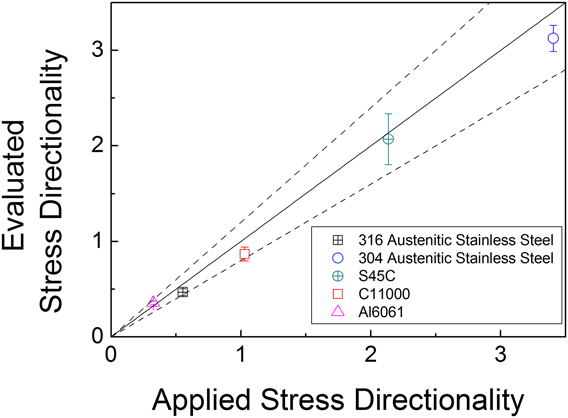
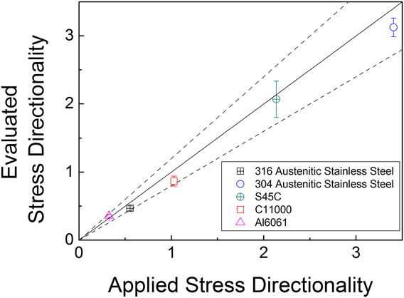
To verify that the stress directionality of the nonequibiaxial stress can be evaluated with the 2.6:1 modified Berkovich indenter, indentation tests were carried out for various materials and nonequibiaxial stress states. The applied stress directionalities were evaluated using the conversion factor ratio of 0.58 as shown in Fig. 6. The upper dotted line and the lower dotted line of Fig. 6 show a 20% error level, that is, the maximum error of the evaluated stress directionality is less than 20%. This result implies that the method of evaluating the stress directionality proposed in this study and the conversion factor ratio for the 2.6:1 modified Berkovich indenter are accurate and reasonable.
Comparison of evaluated and applied stress directionalities of cruciform specimens.
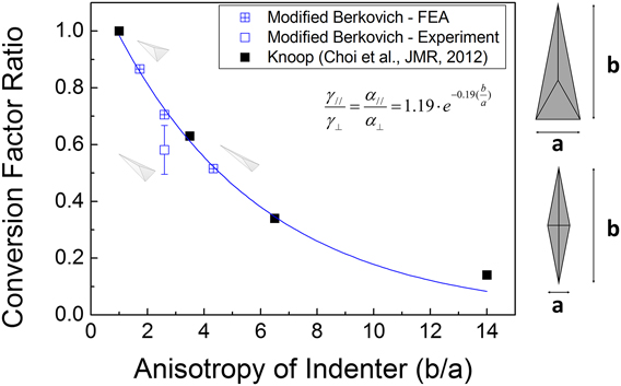
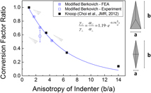
The conversion factor ratio value for the 2.6:1 modified Berkovich indenter is 0.58, larger than the 0.34 for the Knoop indenter.Reference Jae-Hwan Han, Lee, Choi, Lee, Kim and Kwon12,Reference Choi, Kang, Kang and Kwon13 In previous research, Choi et al.Reference Choi, Kang, Kang and Kwon13 confirmed that the conversion factor ratio for Knoop indentation depends on the diagonal ratio of the Knoop indenter. As the ratio of the long to short diagonals of the Knoop indenter increases, the conversion factor ratio gradually decreases. And AhnReference Ahn, Kim, Xu, Lee, Kim, Kim and Kwon15 found that the conversion factor ratio for a wedge indenter depends on the indentation depth because wedge indenter does not have geometrical self-similarity. The residual imprint of the wedge indenter is rectangular and as the indentation depth increases, due to the shape of the wedge indenter, the length of one side of the rectangle remains constant while that of the other side increases continuously. As in Knoop indentation, the conversion factor ratio for wedge indentation increases as the ratio of the long side to the short side of the rectangle decreases. In other words, if the anisotropy increases as the indenter is extended in one direction, the conversion factor ratio becomes smaller. The modified Berkovich indenter is also a type of indenter that is extended in a specific direction and has an anisotropic shape, similar to the Knoop indenter. But, compared to the ratio of long diagonal to short diagonal of the Knoop indenter which is 7.11:1, our 2.6:1 modified Berkovich indenter is less anisotropic. Therefore, the conversion factor ratio for the 2.6:1 modified Berkovich indenter seems to be relatively large compared to the Knoop indenter. If the modified Berkovich indenter is extended further, the conversion factor ratio value will be smaller; if it is shortened, the conversion factor ratio value will be larger. In this research, we obtained both normal and parallel conversion factors for the 1.7:1 and 4.3:1 modified Berkovich indenters and calculated the conversion factor ratios using finite element analysis. The conversion factor ratio of the 1.7:1 modified Berkovich indenter was 0.87 and that for the 4.3:1 modified Berkovich indenter was 0.51 (Fig. 7). Comparison to the conversion factor ratio of 0.58 for the 2.6:1 modified Berkovich indenter shows that the conversion factor ratio becomes smaller when the indenter is lengthened and larger when it is shortened.
Relation between anisotropy of indenter (b/a) and conversion factor ratio.
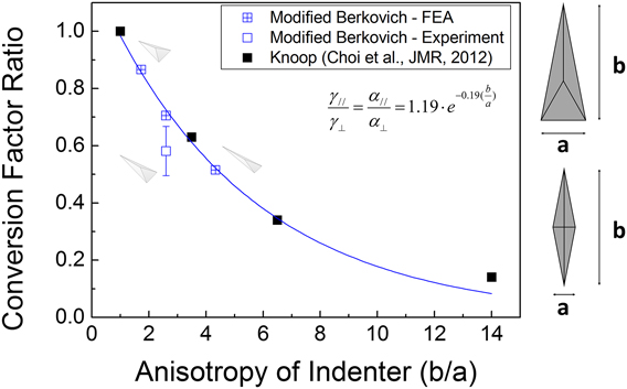
The conversion factor ratio value of the 2.6:1 modified Berkovich indenter obtained using the finite element analysis is 0.71, which is different from the experimentally obtained 0.58. Choi et al.,Reference Choi, Kang, Kang and Kwon13 using experiments and finite-element analysis, confirmed the dependency of the conversion factor ratio on the ratio of long diagonal to short diagonal which represents the anisotropy of the Knoop indenter. And, as shown in Fig. 7, it can be confirmed that the conversion factor ratios for the 1.7:1, 2.6:1, and 4.3:1 modified Berkovich indenters obtained using finite element analysis in this research match well with previous research results. This means that b/a, the ratio of the Knoop indenter’s long to short diagonals in previous research can also be applied to the ratio of the height to the base of the modified Berkovich indenter, as shown in the right of Fig. 7 and represents the anisotropy of indenters because the conversion factor ratio depends on it. From the results of the Knoop indenter and modified Berkovich indenter, b is the line of maximum length symmetrically separating the particular indenter’s projected shape and a is the line of maximum length in a direction perpendicular to this. If b and a have the same value, the conversion factor ratio is 1 because there is no anisotropy in that indenter, and as the b/a increases, the conversion factor ratio decreases because the anisotropy of the indenter increases (Fig. 7). Using the b/a and conversion factor ratio values obtained from this and previous research, the empirical relationship of previous research can be modified as follows:
 $${{{\gamma _{\parallel} }} \over {{\gamma _ \bot }}} = {{{\alpha _{\parallel} }} \over {{\alpha _ \bot }}} = 1.19 \cdot {{\rm{e}}^{ - 0.19\left( {{b \over a}} \right)}}\quad .$$
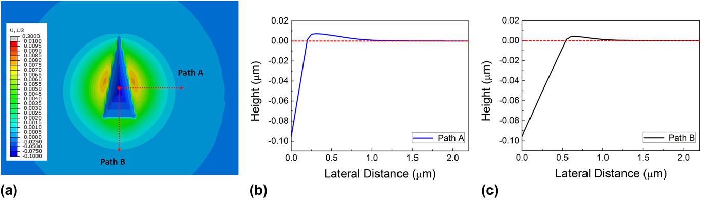
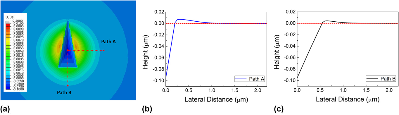
Figure 7 shows that the conversion factor ratios for the 1.7:1, 2.6:1, and 4.3:1 modified Berkovich indenters obtained by the finite element analysis agree well with Eq. (9), but the conversion factor ratio for the 2.6:1 modified Berkovich indenter obtained from the experiment is slightly undervalued. According to work by Giannakopoulos,Reference Giannakopoulos and Zisis20 if elastoplastic behavior is assumed in Knoop indentation, the ratio of the long diagonal to the short diagonal of the residual imprint is 6.72:1 even when tested with a 7.11:1-shaped Knoop indenter. And finite element analysis of the 2.6:1 modified Berkovich indenter indicates that more pile-up occurs next to the residual imprint in a direction normal to the extended axis (Path A) than to the extended axis (Path B) as shown in Fig. 8. This means that the height-to-base ratio of the residual imprint would be smaller than the height-to-base ratio of the manufactured indenter. From the results of previous Knoop indenter research and the finite element analysis of the modified Berkovich indenter, the height-to-base ratio of the residual imprint should be less than the ratio of the modified Berkovich indenter. After indentation testing of the 2.6:1 modified Berkovich indenter, we observed the residual imprint using scanning electron microscopy (SEM, FEI Quanta 250) and found that the height-to-base ratio of the residual imprint was about 2.6:1 to 2.7:1 [Fig. 1(c)]. It can be deduced that the height-to-base ratio of the manufactured indenter in this research is greater than 2.6:1, and the difference in the height-to-base ratio may have affected the conversion factor ratio of the 2.6:1 modified Berkovich indenter in Fig. 7. Therefore, the blue empty rectangle corresponding to the experimental value of the 2.6:1 modified Berkovich indenter in Fig. 7 should be shifted to the right slightly along the x-axis. Additionally, considering the standard deviation of the conversion factor ratio of the experimental 2.6:1 modified Berkovich indenter, we can confirm that the value obtained in the experiment agrees with the value predicted by the finite element analysis.
Pile-up distribution for the 2.6:1 modified Berkovich indenter from finite element analysis (a) top view, (b) surface profile distribution of Path A, and (c) surface profile distribution of Path B.
The results of this and previous research demonstrate that we can use Eq. (9) in evaluating the stress directionality of residual stress using a modified Berkovich indenter of the proposed height-to-base ratio or a new ratio in nanoindentation, or using a Knoop indenter in microindentation. In addition, if further study is performed, the modified Berkovich indenter can be used to evaluate the principal direction of the stress state as in the Knoop study performed by Kim et al.Reference Kim, Choi, Kwon and Kim14 because it also has a constant conversion factor ratio like Knoop indenter. Furthermore, to apply this technique to various stress states, this method, which has been verified only in the tensile stress state, should be verified in a compressive stress state. Previous studiesReference Suresh and Giannakopoulos4,Reference Lee and Kwon21,Reference Xiao, Ye and Chen22 have shown that the indentation curves are differently affected by tensile residual stress and compressive residual stress. Therefore, further study will be needed based on the proposed model here in the compressive stress state. In addition, we proposed a new shape of indenter in this study without the contact area function because the contact area is not required in this study. However, the modified Berkovich indenter can also be extended to studies evaluating the anisotropic properties of the material, such as Knoop indenter, which should include consideration of the contact area function. If the above further studies are processed, this new modified Berkovich indenter can be widely used as an indenter to evaluate and characterize the material properties, especially the information of anisotropic properties, in nanoindentation.
V. CONCLUSIONS
We suggested a modified Berkovich indenter by extending a conventional Berkovich indenter in one direction to evaluate the stress directionality using nanoindentation. We obtained conversion factor values from the slope in relation to uniaxial stress and indentation load difference. The conversion factor ratio for the 2.6:1 modified Berkovich indenter is constant as 0.58 regardless of indentation depth and material. We demonstrated that stress directionality in nonequibiaxial stress states can be evaluated using the 2.6:1 modified Berkovich indenter within ±20%. Conversion factor ratios for the 4.3:1 and 1.7:1 modified Berkovich indenters were obtained by finite element analysis as 0.51 and 0.87, respectively. The experimental and finite element analysis results show that the conversion factor ratios depend on the height-to-base ratio of the modified Berkovich indenter, just like the diagonal ratio of the Knoop indenter. Both ratios are the ratio of maximum length of the indenter to its maximum length in a perpendicular direction.
ACKNOWLEDGMENTS
This work was supported by the National Research Foundation of Korea (NRF) grant funded by the Korea government (MSIT) (Nos. NRF-2015R1A5A1037627 and NRF-2018R1D1A3B07048712) and the Korea Institute of Energy Technology Evaluation and Planning (KETEP) and the Ministry of Trade, Industry & Energy (MOTIE) of the Republic of Korea (No. 20171520000360).