I. INTRODUCTION
Solid oxide fuel cells (SOFCs) are regarded as a promising power generation system due to the high-energy conversion efficiency comparing with that of other type fuel cells. In addition, SOFCs can use various fuels such as hydrocarbon or alcohol without a precious metal catalyst such as Pt.Reference Yamamoto1–Reference Minh3 The fuel flexibility is originated from the internal gas reforming, which is highly effective for improving the efficiency. However, materials used for SOFCs are limited by ceramics, and a long start-up period is requested due to the high operating temperature. Therefore, at present, there are many efforts to operate SOFCs at intermediate temperature, which is also effective for extending the application area of SOFCs. However, the power density and conversion efficiency significantly decrease with reducing the operation temperature because of the enlarged internal resistance (IR) of electrolyte. Various investigations have been focused on the discovery of a new electrolyte materialReference Yahiro, Baba, Eguchi and Arai4–Reference Ju, Eto, Inagaki and Ishihara22 and the fabrication of a thin electrolyte filmReference Yan, Lu, Jiang, Dong, Yu and Li15–Reference Yamaguchi, Hashimoto, Sakata, Kajiware, Watanable, Setiguchi, Eguchi and Arai26 to reduce the electrolyte resistance, which is mainly dominated by low conductivity and large thickness of electrolyte. Among new electrolyte materials, La0.9Sr0.1Ga0.8Mg0.2O3−δ (LSGM) has been considered as an excellent electrolyte material for intermediate temperature solid oxide fuel cells (IT-SOFCs) because it has high oxide ionic conductivity at intermediate temperatures and high transference number of oxide ions over a wide range of oxygen partial pressures.Reference Ishihara, Matsuda and Takita7–Reference Huang, Tichy and Goodenough11 However, LSGM electrolyte has some drawbacks such as the reactivity with the electrode materialsReference Huang, Tichy and Goodenough11, Reference Huang, Wan and Goodenough12 and poor mechanical strength compared with that of Y2O3-stabilized ZrO2.
We have introduced a Ni–Fe metal-supported SOFC having a thin LSGM electrolyte film to solve the problem for poor mechanical strength, in our previous study.Reference Yan, Matsumoto, Enoki and Ishihara19–Reference Ju, Inagaki, Ida and Ishihara24 In addition, we confirmed that the reaction between the LSGM electrolyte and Ni in the anode was prevented by inserting a Sm-doped CeO2 (SDC) thin buffer layer and decreasing the sintering temperature of the LSGM electrolyte film prepared by a pulsed laser deposition (PLD). The PLD is unique method to fabricate thin and uniform film at a lower temperature compared with other fabrication methods such as tape casting,Reference Minh, Armstrong, Esopa, Guiheen, Home and van Ackeren25 screen printing,Reference Yamaguchi, Hashimoto, Sakata, Kajiware, Watanable, Setiguchi, Eguchi and Arai26 spin coating,Reference Chen, Nasrallah and Anderson27 colloidal deposition,Reference de Souza, Visco and De Jonghe28 plasma spraying,Reference Lunot, Denos and Dolenc29, Reference Li, Li, Xing, Gao and Yang30 electrostatic-assisted vapor deposition,Reference Bai, Choy, Rudkin and Steele31 and physical vapor deposition.Reference Wang, Thiele and Barnett32 Therefore, many research groups have adopted for fabricating SOFC having thin film despite of difficulty in the scale-up of cell size. The prepared metal-supported SOFC has exhibited high power density at intermediate temperatures (from 973 to 773 K) and good tolerances against thermal and redox cycling. However, after a long-term operation for 100 h, the cell performance has degraded because of the interdiffusion of La from the LSGM electrolyte to the SDC buffer layer. The diffused La forms a La-doped CeO2 (LDC) in the SDC layer, which is known to have a lower conductivity than that of SDC. In addition, a secondary phase LaSrGa3O7 structure is produced in the LSGM electrolyte layer because of the La migration to the SDC layer resulting in the decrease of power generation property.Reference Huang, Tichy and Goodenough11, Reference Huang, Wan and Goodenough12 Therefore, an investigation on a new buffer layer for a LSGM electrolyte film is necessary for fabricating excellent and stable metal-supported IT-SOFCs.
In this study, we investigated various materials such as doped CeO2, SrTiO3, and LaCrO3 as a buffer layer for metal-supported SOFCs using a LSGM thin electrolyte film prepared using the PLD method. Among materials studied, 40 mol% LDC and 19 mol% Pr-doped LaCrO3 (LPCr) showed no reactivity with LSGM and Ni. Therefore, we further investigated long-term stability on metal-supported cells using the LDC or LPCr as buffer layer.
II. EXPERIMENT
A. Preparation of buffer layer materials
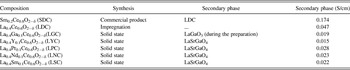
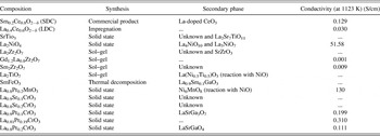
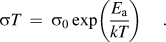
For development of a new buffer layer material, two kinds of approach were adopted. One is to modify doped CeO2, particularly for 40 mol% LDC by codoping [(Ce0.5La0.4M0.1)O2−δ, M = Ga, Y, Pr, Nd, and Sm], which was prepared by a typical solid-state reaction (Table I). Another is to introduce mixed ionic and electronic conductors (MIECs) as a buffer layer. The MIEC materials were prepared by a typical solid-state reaction, sol–gel method, or impregnation method, respectively, as summarized in Table II. X-ray diffraction (XRD) using CuKα radiation (Rint 2500, Rigaku, Tokyo, Japan) was measured to determine phase formation of all prepared materials. To confirm the reactivity of a buffer layer material against NiO or LSGM, the prepared powder was mixed with commercial NiO or prepared LSGM in an agate mortar. After calcination of the mixture at 1623 K for 6 h, the reactivity was confirmed by powder XRD analysis. The electrical conductivity of each material was measured by using dc four-probe method with rectangular bar sample in air at the temperature rage of 673–1173 K. A Pt wire was connected to the conductivity sample with Pt paste. The activation energy of measured conductivity data was calculated using the Arrhenius equation as following:
Summary of properties of co-doped ceria.

Summary of investigated materials for new buffer layer.

B. Fabrication of metal-supported cell and electrochemical measurements
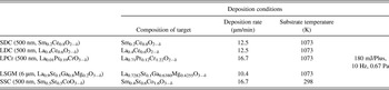
Ten wt% Fe2O3-coated NiO powder was prepared by a traditional impregnation method. Fe(NO3)3·9H2O was dissolved in deionized water, and then, NiO powder was added into the solution proportionately. After the evaporation of water, the obtained powder was calcined in a ventilated furnace at 673 K for 2 h to decompose nitrate acid and then fired at 1473 K for 6 h. To obtain a fine and uniform particle mixture, the mixed powder was ground for 1 h in ethanol using the ball milling process with zirconia balls. After drying the slurry, the resulting powder was pressed into disks (20 mm in diameter) at 20 MPa. After isostatically pressing at 48 MPa, the obtained disks were sintered at 1723 K for 5 h in air; the thickness of substrate was 1.7 mm.Reference Ju, Matsumoto, Ishihara, Inagaki and Eto21–Reference Ju, Eto, Inagaki and Ishihara23 Thin La0.9Sr0.1Ga0.8Mg0.2O3 (LSGM) electrolyte and Ce0.8Sm0.2O2 (SDC) buffer layer films were then deposited onto the dense anode substrate via the PLD method using a commercial system with a vacuum chamber (PLD-7, PASCAL, Itami, Japan). Before deposition, the substrate was heated to 1073 K with an infrared heater, and the oxygen pressure during deposition was adjusted to 0.67 Pa by introducing commercial oxygen without purification. The power and frequency of excimer laser were adjusted to 180 mJ/pulse and 10 Hz, respectively. Molar ratio of La, Sr, Ga, and Mg in optimized target for deposition of LSGM electrolyte was La:Sr:Ga:Mg = 0.7282:0.1:0.6380:0.4255. For fabricating a thin buffer layer film, each target disk having an optimized composition was prepared using a solid-state reaction as listed in Table III. A thin convex-shaped Sm-doped SrCo3 (SSC) layer as the cathode was fabricated via the PLD method with an optimized SSC target composition on the thin LSGM film after postannealing in air at 1073 K for 2 h.Reference Ju, Inagaki, Ida and Ishihara24 For preparing the SSC layer, target disk was fabricated by conventional solid-state reaction method using Sm2O3, SrCO3, and Co3O4 as the starting materials. Molar ratio of the optimized target composition was Sm:Sr:Co = 0.4:0.6:1.6. The diameter of the deposited SSC layer was 5 mm. A SSC powder cathode (around 20 μm) was then prepared using a slurry coating method on the deposited SSC film and then fired at 1073 K for 30 min. A Pt wire was connected to the LSGM film near the cathode as the reference electrode.
Fabrication condition for deposited film.

The power generation property of a metal-supported cell was measured by the four-probe method. Humidified H2 (2.8 vol% H2O) and commercial oxygen were fed to the cell as fuel and oxidant, respectively. The gas flow rate was kept to be 100 mL/min in this study. A constant current was applied by using a galvanostat (HA-301, Hokuto Denko, Tokyo, Japan), and the potential was measured with a digital multimeter (Digital Multimeter R6451A, Advantest, Tokyo, Japan). IR drop and overpotential were estimated by the current interruption method. A current pulse was generated with a current pulse generator (Current Pulse Generator HC111, Hokuto Denko, Tokyo, Japan) and the residual potential response was analyzed with a memory hicoder (Memory Hicoder 8835, Hioki, Nagano, Japan). Microstructure of the cell was studied using a scanning electron microscope (SEM, VE-7800; KEYENCE, Osaka, Japan)/energy dispersive x-ray spectroscopy (EDX) after the cell test.
III. RESULTS AND DISCUSSION
A. Investigation for codoped ceria
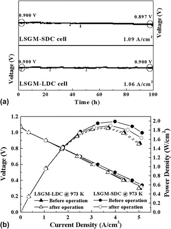
Figure 1 shows the power generating property of a metal-supported cell using a SDC or LDC buffer layer. The cell having a SDC buffer layer shows a small degradation in the voltage (0.900–0.897 V) after operating at 1.09 A/cm2 of the applied current density for 100 h at 973 K. On the contrary, the cell using a LDC buffer layer shows no degradation in the cell voltage when operated at 1.06 A/cm2 of the current density as shown in Fig. 1(a). Thus, the cell using the LDC buffer layer reveals improved long-term stability compared with the cell using the SDC buffer layer. However, the applied current density at 0.9 V in the cell using the LDC buffer layer is lower than that of the cell with the SDC layer. In addition, the cell using the LDC layer shows lower maximum power density (MPD) (1.86 W/cm2 at 973 K) than that of the cell using the SDC layer (1.99 W/cm2 at 973 K) as shown in Fig. 1(b). The low performance in the cell with the LDC layer is mainly related with a high IR of the cell compared to that using the SDC buffer layer because the electrical conductivity of LDC is lower than that of SDC. However, the MPD is stable after the long-term operation at 973 K for the cell having LDC buffer layer (1.86–1.84 W/cm2), while the cell using the SDC buffer layer decreases from 1.99 to 1.90 W/cm2. The degradation of the MPD in the cell with the SDC buffer layer is attributed to the formation of a secondary phase in the SDC layer and LaSrGa3O7 phase in the LSGM electrolyte layer during operation.Reference Huang, Tichy and Goodenough11, Reference Huang, Wan and Goodenough12, Reference Ju, Inagaki, Ida and Ishihara24 Therefore, to fabricate a more reliable and powerful metal-supported SOFC, it is necessary to investigate a new buffer layer, which has a higher conductivity than that of LDC and a prior chemical compatibility than that of SDC.
The power generating property of the metal-supported cell having SDC and LDC buffer layer electrolyte film; (a) long-term performance at 973 K and (b) IV–IP curves.

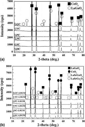
Yamamura et al.Reference Yamamura, Katoh, Ichikawa, Kakinuma, Tori and Haneda33 and KimReference Kim34 found that codoping led to the increase of the ionic conductivity of doped CeO2 and the reduction of the activation energy for conduction. Huang et al.Reference Huang, Wan and Goodenough12 reported that 40 mol% LDC had no reactivity with the LSGM, and the La diffusion was originated from the difference of La concentration between the LSGM and LDC. Thus, codoping for LDC was investigated for increasing conductivity. La concentration in the LDC was kept as 40 mol% for maintaining chemical compatibility, and 10 mol% secondary dopant was replaced with the Ce site. Figure 2(a) shows XRD patterns of Ce0.5La0.4M0.1O2−δ (M = Ga, Y, Pr, Nd, and Sm, denoted as LGC, LYC, LPC, LNC, and LSC, respectively) sintered at 1573 K and a powder mixture consisting of LSGM and Ce0.5La0.4M0.1O2−δ (1:1 wt%) after sintering at 1623 K [Fig. 2(b)]. The LYC, LPC, and LSC show a typical cubic fluorite structure without any secondary phases as shown in Fig. 2(a). However, the LGC shows a perovskite structure (LaGaO3; JCPDS powder diffraction File No. 83-0566) as secondary phase. The LaGaO3 secondary phase is attributed to the reaction between two dopants (La and Ga) during solid-state reaction. In addition, LYC, LPC, LNC, and LSC show an impurity phase of LaSrGaO4 after calcination at 1623 K for 5 h with LSGM. Huang et al.Reference Huang, Wan and Goodenough12 reported that the formation of LaSrGaO4 is originated from La diffusion from the LDC buffer layer to the LSGM electrolyte, while the LaSrGa3O7 phase is formed owing to La deficiency in the LSGM electrolyte caused by the La migration out of the electrolyte. Thus, it is expected that the LaSrGaO4 formation is induced by an excess dopant in the LYC, LPC, LNC, and LSC. On the other hand, the amount of dopant is insufficient in the LGC due to the formation of LaGaO3 during preparation of LGC.
XRD patterns of (a) (Ce0.5La0.4M0.1)O2−δ and (b) mixtures consisted of LSGM and (Ce0.5La0.4M0.1)O2−δ.

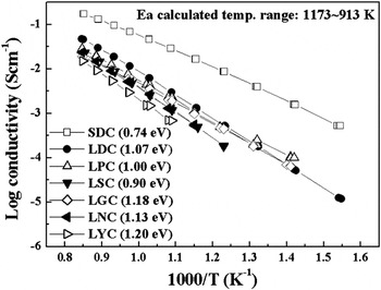
Figure 3 shows the Arrhenius plot for electrical conductivities of codoped LDCs. In the temperature range of 1173–913 K, all codoped LDCs exhibit lower conductivities than that of LDC, although the LPC and LGC show lower activation energies than that of LDC. Thus, codoping LDC (Ce0.5La0.4M0.1O2−δ) is ineffective for improving ionic conductivity and attaining chemical compatibility of LDC.
Arrhenius plot for electrical conductivity of codoped LDC.

B. Investigation for alternative materials as buffer layer
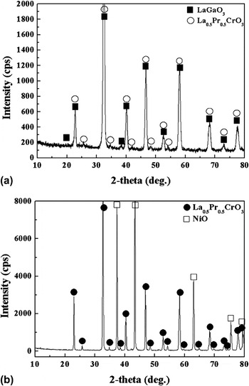
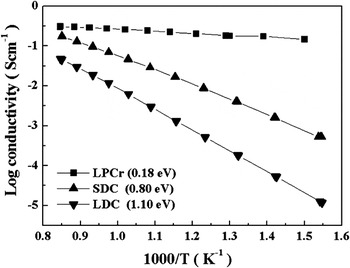
An alternative material was investigated for a buffer layer with high compatibility and conductivity for a LSGM electrolyte film. Various oxide materials for buffer layer studied are summarized in Table II. However, all prepared buffer layer materials form some secondary phases after cosintering with either LSGM or NiO at 1623 K for 6 h, except for LPCr (La0.81Pr0.19CrO3−δ), which shows no reactivity against NiO and LSGM as shown in Fig. 4. Therefore, we focused on the investigation for the LPCr as buffer layer. As shown in Fig. 4(a), the sintered composite of LSGM and LPCr shows no secondary phase such as LaSrGa3O7 and LaSrGaO4. In addition, no impurity or secondary phase is confirmed in the composite of the LPCr and NiO after sintering as shown in Fig. 4(b). Figure 5 shows Arrhenius plot of the electrical conductivity of the LPCr measured by the dc four-probe method in air. The LPCr shows higher conductivity than that of SDC at all temperature ranges. The electrical conductivity of LPCr (0.18 S/cm) is much higher than that of SDC (0.004 S/cm) or LDC (0.0002 S/cm) at 773 K. However, in low oxygen partial pressure at 973 K, the conductivity of LPCr (0.040 S/cm in  = 10−20) is similar with that of LDC (0.037 S/cm in
 = 10−23). As well known, the conductivity of doped CeO2 increased in low oxygen partial pressure. However, the increased conductivity mainly originated from the enhanced electric conductivity. On the contrary, LPCr shows p-type conduction, and the conductivity decreases with decreasing oxygen partial pressure. In the case of a p-type conductor, in reducing atmosphere (
 < 10−8), charge compensation is mainly achieved by oxygen vacancy and the electrical transport is mostly ionic.Reference Zhang35 Therefore, it can be expected that the LPCr has higher oxygen ion conductivity in reducing atmosphere than that of LDC. Therefore, the ohmic resistance of a metal-supported SOFC using the LPCr buffer layer may decrease and the power density may increase.
XRD pattern of a mixture consisting of 19 mol% LPCr and (a) LSGM/(b) NiO after sintering at 1623 K for 6 h.

The Arrhenius plot of conductivity of 19 mol% LPCr and doped CeO2.

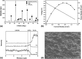
To confirm the power generation property of a metal-supported SOFC with a LPCr buffer layer and LSGM electrolyte films, a thin LPCr film (500 nm) was fabricated on a dense anode substrate by the PLD with an optimized target composition (La0.71Pr0.12Cr1.22O3). A LSGM electrolyte film was then fabricated on the LPCr-deposited film. Figure 6(a) shows XRD pattern of the deposited LSGM–LPCr bilayer electrolyte film after postannealing at 1073 K. The XRD pattern shows NiO and NiFe2O4 phases from the anode support and typical perovskite peaks of the LSGM and LPCr phases. It reveals that the LPCr buffer layer is successfully fabricated with no detectable formation of secondary phases. Thus, electrochemical performance of the cell using the LPCr buffer layer film was investigated. However, the cell shows a lower OCV than the theoretical value as shown in Fig. 6(b). The OCV is also lower than that of the cell using a SDC or LDC buffer layer. In addition, the MPD of the cell using the LPCr buffer layer is 0.4 W/cm2 at 973 K, which is smaller than previous results. A low OCV is normally originated from an electronic conduction or gas leakage in electrolyte layer. However, an electronic conduction of the LSGM electrolyte can be ignored because the electrolyte is a pure oxygen ion conductor, and results of SEM–EDX analysis show no detectable interdiffusion of a cation between the LSGM–LPCr bilayer films and Ni–Fe metal substrate after cell test as shown in Fig. 6(c). Thus, an electronic conduction in the LSGM electrolyte can be excluded for the low OCV. Therefore, a gas leakage may be concerned with the low OCV, although the increment of gas leakage in the cell is negligible during operation, and the deposited electrolyte film is relatively dense as shown in Fig. 6(d).
(a) XRD pattern of the deposited film on NiO–Fe2O3, (b) IV–IP curves of the metal-supported cell having LPCr–LSGM bilayer electrolyte at 973 K, (c) the elements distributions of metal-supported cell after testing, and (d) SEM image of deposited film after testing.

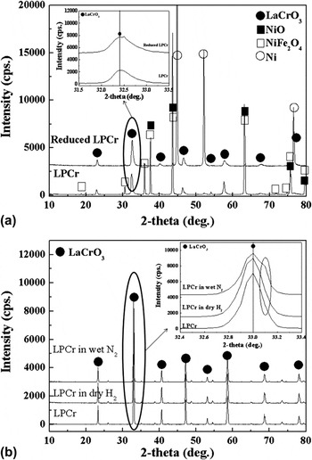
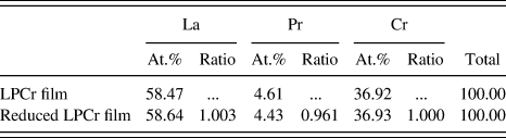
Phase analysis was conducted by XRD measurement for a LPCr film to confirm a reason of the low OCV and power density. Figure 7(a) shows XRD patterns of a LPCr film deposited on the anode substrate before and after reduction in humidified H2 atmosphere for 1 h at 973 K. After reduction, no noticeable impurity phase is observed excluding the change of NiO to Ni. However, XRD peaks of the perovskite phase seem to shift toward a higher diffraction angle. The peak shift indicates a change in lattice parameter or composition. As listed in Table IV, the result of EDX analysis suggests that the amount of Pr in the LPCr film decreases after reduction in the humidified H2. The decrease of Pr content in the LPCr layer may be related with that a Pr(OH) is formed by the reaction of Pr and water as following:

XRD patterns of (a) deposited LPCr film on NiO–Fe2O3 substrate before and after reduction and (b) LPCr disks exposed dry hydrogen and wet nitrogen for 1 h.

Quantitative analysis of LPCr film before and after reducing the NiO–Fe2O3 substrate.
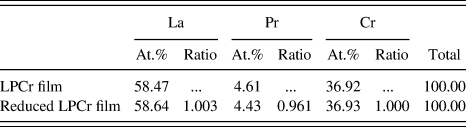
Thus, the composition of the LPCr film contacted with the anode may be changed by the reaction since humidified H2 was supplied into the anode and a small amount of water might be generated by the anode reaction during cell test, resulted in a decrease of the electrical conductivity of the LPCr. To confirm this hypothesis, in which the insufficient performance was caused by the reaction between a LPCr buffer layer and water vapor in the anode environment, the stability of a LPCr film was investigated with XRD analysis after exposing in dry H2 and humidified N2 at 973 K. The LPCr exposed in dry H2 shows no significant change in diffraction patterns as shown in Fig. 7(b). On the other hand, a new but weak peak was appeared at the diffraction angle of 2θ = 33.15° when LPCr was exposed to humidified N2. At present, the formed crystal phase cannot be assigned; however, this suggests that decomposition of LPCr is not caused by simple reduction but by reaction with humidity. This decomposition of LPCr may result in deterioration of the mechanical strength and electrical conductivity of the LPCr film because of the products of low conductivity of a site-deficient LaCrO3 or Cr2O3. Accordingly, the low OCV and power generating performance in the cell using a LPCr buffer layer film may be attributed to the phase decomposition of LPCr layer. Therefore, further detail investigation is requested to use a LPCr buffer layer film in a metal-supported SOFC.
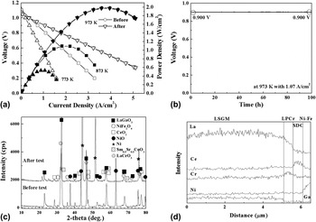
A multilayer electrolyte film, which consisted of LSGM (5 μm), LPCr (300 nm), and SDC (200 nm), was prepared in a metal-supported SOFC using the PLD method. In this cell, the LPCr layer was used for preventing a La migration from the LSGM to SDC, and the SDC layer was intended to prevent the reaction between Pr and water vapor. Figure 8(a) shows the IV–IP curves of the metal-supported cell having the multilayer electrolyte. The cell shows an OCV close to the theoretical value during cell test. It indicates that the mechanical strength of the deposited film is enough to overcome a physical stress originated from the volume change of the metal substrate after reduction and operation temperature change. In addition, the cell shows high maximum power densities 1.98 W/cm2 at 973 K and 0.53 W/cm2 at 773 K, which are similar with the values in the cell with a SDC buffer layer film (1.99 W/cm2 at 973 K and 0.53 W/cm2 at 773 K). Thus, the power densities suggested that electrochemical performance of the cell using the multilayer electrolyte film including LSGM/LPCr/SDC layers was dominated by the SDC layer, although the electrical conductivity of LPCr was higher than that of SDC. However, a long-term performance was more stable in comparison with the cell having a SDC buffer layer film as shown in Fig. 8(b). The cell with the multilayer film shows no degradation in the cell voltage during the operation at 1.07 A/cm2 for 100 h at 973 K. This long-term stability suggests that the LPCr layer effectively prevents the La interdiffusion between the LSGM electrolyte and SDC layers, and the SDC layer is also effective for avoiding the Pr(OH) formation during cell operation. XRD [Fig. 8(c)] and EDX [Fig. 8(d)] analysis results evidently reveal that the LPCr layer successfully prevents the La migration from the LSGM electrolyte. Therefore, it is expected that a LPCr can be used as an effective buffer layer for a metal-supported SOFC using a LSGM electrolyte film after preventing the reaction with water vapor.
(a) IV–IP curves and (b) long-term operations at 973 K of the metal-supported cell having SDC–LPCr–LSGM multilayer electrolyte, (c) XRD pattern of the metal-supported cell having LPCr–SDC–LSGM electrolyte, and (d) elements distributions of the metal-supported cell after testing.

IV. CONCLUSIONS
Various materials were investigated as a buffer layer for fabricating a reliable metal-supported SOFC using a LaGaO3-based electrolyte thin film. For materials studied, 40 mol% LDC and 19 mol% LPCr showed no reactivity with a LSGM electrolyte and NiO–Fe2O3 anode, respectively. A metal-supported cell using the LDC buffer layer showed low power density due to the low conductivity of LDC, while long-term performance of the cell was stable after operation for 100 h. In contrast, when the LPCr was used as buffer layer for a metal-supported SOFC, the cell showed significantly low OCV and power density, which was attributed to the decomposed Pr in the LPCr caused by the reaction with water vapor. However, the metal-supported SOFC using a multilayer electrolyte including LSGM, LPCr, and SDC films showed almost theoretical OCV and high power density, which was similar with that of the cell using a SDC buffer layer, and no degradation in the performance after operation for 100 h at 973 K. Consequently, this study reveals that a LPCr–SDC bilayer is a highly useful buffer layer for a reliable metal-supported SOFC using a LSGM electrolyte film prepared by PLD method.