1. Introduction
This paper examines the role of body elasticity in two-dimensional viscous streaming. Viscous streaming (Holtsmark et al. Reference Holtsmark, Johnsen, Sikkeland and Skavlem1954; Lane Reference Lane1955; Bertelsen, Svardal & Tjøtta Reference Bertelsen, Svardal and Tjøtta1973), an inertial phenomenon, refers to the time-averaged, rectified steady flows that arise when an immersed body of length scale  $a$ undergoes small-amplitude oscillations in a viscous fluid. Long understood for rigid bodies of uniform curvature, such as cylinders (Holtsmark et al. Reference Holtsmark, Johnsen, Sikkeland and Skavlem1954) or spheres (Lane Reference Lane1955), viscous streaming has found application in microfluidics (Lutz, Chen & Schwartz Reference Lutz, Chen and Schwartz2003, Reference Lutz, Chen and Schwartz2005; Marmottant & Hilgenfeldt Reference Marmottant and Hilgenfeldt2004; Lutz, Chen & Schwartz Reference Lutz, Chen and Schwartz2006; Wang, Jalikop & Hilgenfeldt Reference Wang, Jalikop and Hilgenfeldt2011; Chong et al. Reference Chong, Kelly, Smith and Eldredge2013; Chen & Lee Reference Chen and Lee2014; Klotsa et al. Reference Klotsa, Baldwin, Hill, Bowley and Swift2015; Thameem, Rallabandi & Hilgenfeldt Reference Thameem, Rallabandi and Hilgenfeldt2017; Pommella et al. Reference Pommella, Harun, Hellgardt and Garbin2021), from chemical mixing (Liu et al. Reference Liu, Yang, Pindera, Athavale and Grodzinski2002; Lutz et al. Reference Lutz, Chen and Schwartz2003, Reference Lutz, Chen and Schwartz2005; Ahmed et al. Reference Ahmed, Mao, Juluri and Huang2009) to vesicle transport (Marmottant & Hilgenfeldt Reference Marmottant and Hilgenfeldt2003, Reference Marmottant and Hilgenfeldt2004), due to its ability to reconfigure flow and particle trajectories within short length –
 ${O} \left ( {100} \right )\,\mathrm {\mu }$m – and time –
 ${O} \left ( {10^{-3}} \right )$ s – scales (Thameem, Rallabandi & Hilgenfeldt Reference Thameem, Rallabandi and Hilgenfeldt2016; Thameem et al. Reference Thameem, Rallabandi and Hilgenfeldt2017). Recent developments have then furthered opportunities in transport, separation or assembly, through the use of multi-curvature bodies and associated rich flow topologies (Parthasarathy, Chan & Gazzola Reference Parthasarathy, Chan and Gazzola2019; Bhosale, Parthasarathy & Gazzola Reference Bhosale, Parthasarathy and Gazzola2020; Bhosale et al. Reference Bhosale, Vishwanathan, Parthasarathy, Juarez and Gazzola2021b; Chan et al. Reference Chan, Bhosale, Parthasarathy and Gazzola2022).
Despite progress, no effort has so far systematically considered the role of body elasticity in viscous streaming. Yet, modulation by soft interfaces may be relevant in a multitude of settings, from pulsatile physiological flows (Jalal et al. Reference Jalal, Van de Moortele, Nemes, Amili and Coletti2018; Parthasarathy, Bhosale & Gazzola Reference Parthasarathy, Bhosale and Gazzola2020; Jacob, Tingay & Leontini Reference Jacob, Tingay and Leontini2021) or conformal microfluidics (Someya, Bao & Malliaras Reference Someya, Bao and Malliaras2016; Heikenfeld et al. Reference Heikenfeld, Jajack, Rogers, Gutruf, Tian, Pan, Li, Khine, Kim and Wang2018; Bandodkar et al. Reference Bandodkar2019) to elastic mini-robots in fluids (Park et al. Reference Park2016; Ceylan et al. Reference Ceylan, Giltinan, Kozielski and Sitti2017; Aydin et al. Reference Aydin, Zhang, Nuethong, Pagan-Diaz, Bashir, Gazzola and Saif2019; Huang et al. Reference Huang, Uslu, Katsamba, Lauga, Sakar and Nelson2019), with relevance to both medicine and engineering. Soft biological organisms, such as bacteria (Spelman & Lauga Reference Spelman and Lauga2017) or larvae (Gilpin, Bull & Prakash Reference Gilpin, Bull and Prakash2020), may also take advantage of streaming for feeding or locomotion. Indeed, a back of the envelope calculation reveals that a millimetre-size aquatic organism beating its cilia at  ${\sim }{O} \left ( {10} \right )$ Hz would operate at the edge of viscous streaming viability. Supporting this hypothesis, steady flow patterns and velocities (
 ${\sim }10^{2}\unicode{x2013}10^{3}\,\mathrm {\mu }{\rm m}\,{\rm s}^{-1}$) consistent with streaming have been observed in starfish and ribbon-worm larvae (Gilpin et al. Reference Gilpin, Bull and Prakash2020), although being ascribed, perhaps inaccurately, to Stokes flow phenomena.
Motivated by these considerations, we dissect the effect of body elasticity on viscous streaming in the minimal setting of an immersed, oscillating hyperelastic circular cylinder. The major outcome is that, in these conditions, the time-averaged streaming flow  $\langle \psi _1 \rangle$ reads
 \begin{equation} \langle \psi_1 \rangle = \sin 2 \theta \left[ \varTheta(r) + \varLambda(r) \right], \end{equation}
where  $r, \theta$ are cylindrical coordinates,
 $\varTheta (r)$ is the classical rigid-body solution from Holtsmark et al. (Reference Holtsmark, Johnsen, Sikkeland and Skavlem1954) and
 $\varLambda (r)$ is a novel, independent contribution from body elasticity.
2. Problem set-up and governing equations
The above result is obtained by considering the set-up shown in figure 1, where a 2-D viscoelastic solid cylinder  $\varOmega _e$ with radius
 $a$ is immersed in a viscous fluid
 $\varOmega _f$. The fluid oscillates with velocity
 $V(t) = \epsilon a \omega \cos \omega t$, where
 $\epsilon$,
 $\omega$ and
 $t$ represent the non-dimensional amplitude, angular frequency and time, respectively. We ‘pin’ the cylinder's centre using a rigid inclusion
 $\varGamma$ of radius
 $b < a$, to kinematically enforce zero strain and velocity near the cylinder's centre. We denote by
 $\partial \varOmega$ and
 $\partial \varGamma$ the boundary between the elastic solid and viscous fluid, and the boundary of the pinned zone, respectively.
Problem set-up. Elastic solid cylinder  $\varOmega _e$ of radius
 $a$ with a rigid inclusion (pinned zone
 $\varGamma$ of radius
 $b$), immersed in the viscous fluid
 $\varOmega _f$. The cylinder is exposed to an oscillatory flow with far-field velocity
 $V(t) = \epsilon a \omega \cos (\omega t)$.

In this set-up, we assume fluid and solid to be isotropic, incompressible and of constant density. Furthermore, we assume the fluid to be Newtonian, with kinematic viscosity  $\nu _f$ and density
 $\rho _f$. We assume that the solid exhibits viscoelastic Kelvin–Voigt behaviour, where the elastic stresses are modelled via neo-Hookean hyperelasticity, characteristic of soft biological materials (Bower Reference Bower2009), with shear modulus
 $G$, kinematic viscosity
 $\nu _e$ and density
 $\rho _e$. Nonetheless, as it will later become apparent, the choice of hyperelastic or viscoelastic model does not affect the general theory presented in this study. This is because in the analysis that follows, higher order nonlinear terms in the stress–strain or viscous response drop out, reducing to linear elasticity.
The dynamics in the elastic and fluid phases are described by the incompressible Cauchy momentum equations, non-dimensionalized using the characteristic scales of velocity  $V = \epsilon a \omega$, length
 $L = a$, time
 $T = 1 / \omega$ and hydrostatic pressure
 $P = \mu _f V / L = \mu _f \epsilon \omega$:
 \begin{align} \left. \begin{aligned} \text{Incomp.} & \begin{cases} {\boldsymbol{\nabla}} {\boldsymbol{\cdot}} {\boldsymbol{v}} = 0, \ {\boldsymbol{x}}\in \varOmega_f \cup \varOmega_e \end{cases}\\ \text{Fluid} & \begin{cases} \dfrac{\partial {{\boldsymbol{v}}}}{\partial {t}} + \epsilon ({{\boldsymbol{v}}} {\boldsymbol{\cdot}} {{\boldsymbol{\nabla}}}) {{\boldsymbol{v}}} = \dfrac{1}{M^{2}} \left(-{\boldsymbol{\nabla}}{p} + {\nabla^{2}} {{\boldsymbol{v}}} \right),\ {{\boldsymbol{x}}}\in\varOmega_f \end{cases}\\ \text{Solid} & \begin{cases} \alpha \mathrm{Cau} \left( \dfrac{\partial {{\boldsymbol{v}}}}{\partial {t}} + \epsilon ({{\boldsymbol{v}}} {\boldsymbol{\cdot}} {{\boldsymbol{\nabla}}}) {{\boldsymbol{v}}} \right) = \dfrac{\mathrm{Cau}}{M^{2}} \left( -{\boldsymbol{\nabla}} {p} + \beta {\nabla^{2}} {{\boldsymbol{v}}} \right) + {{\boldsymbol{\nabla}}} {\boldsymbol{\cdot}} ({{\boldsymbol{F}}} {{\boldsymbol{F}}}^{\rm T}){'} ,~{{\boldsymbol{x}}}\in\varOmega_e, \end{cases} \end{aligned} \right\} \end{align}
where  $ {\boldsymbol {v}}$ and
 $p$ are the velocity and pressure fields, and
 $ {\boldsymbol {F}}$ is the deformation gradient tensor, defined as
 $ {\boldsymbol {F}} = {\boldsymbol {I}} + {\boldsymbol {\nabla }} {\boldsymbol {u}}$, where
 $ {\boldsymbol {I}}$ is the identity,
 $ {\boldsymbol {u}} = {\boldsymbol {x}} - {\boldsymbol {X}}$ is the material displacement field and
 $ {\boldsymbol {x}}$,
 $ {\boldsymbol {X}}$ are the position of a material point after deformation and at rest, respectively. The prime symbol
 ${'}$ on a tensor denotes its deviatoric. In addition, the following non-dimensional groups naturally appear: scaled oscillation amplitude
 $\epsilon$, Womersley number
 $M = a \sqrt {\rho _f \omega / \mu _f}$, Cauchy number
 $\mathrm {Cau} = \epsilon \rho _f a^{2} \omega ^{2} / G$, density ratio
 $\alpha = \rho _e / \rho _f$ and viscosity ratio
 $\beta = \mu _e / \mu _f$. Physically,
 $M$ represents the ratio of inertial to viscous forces, and
 $\mathrm {Cau}$ represents the ratio of inertial to elastic forces. Thus, increasing
 $M$ indicates an inertia-dominated environment, and increasing
 $\mathrm {Cau}$ implies a softer body. The equations are then closed using the boundary conditions
 \begin{gather} \text{Pinned zone} \ \begin{cases} {\boldsymbol{u}} = 0, {\boldsymbol{v}} = 0, {\boldsymbol{x}}\in \varGamma, \end{cases} \end{gather}
 \begin{gather}\text{Interface velocity}\ \begin{cases} {\boldsymbol{v}}_e = {\boldsymbol{v}}_f,~{\boldsymbol{x}}\in\partial\varOmega, \end{cases} \end{gather}
 \begin{gather}\text{Interface stresses}\ \begin{cases} {\boldsymbol{\sigma}}_{f} ={-}p{\boldsymbol{I}} + ({\boldsymbol{\nabla}} {\boldsymbol{v}} + {\boldsymbol{\nabla}} {\boldsymbol{v}}^{\rm T}),\ {\boldsymbol{x}}\in\varOmega_f, \\ {\boldsymbol{\sigma}}_{e} ={-}p{\boldsymbol{I}} + \beta ({\boldsymbol{\nabla}} {\boldsymbol{v}} + {\boldsymbol{\nabla}} {\boldsymbol{v}}^{\rm T}) + \dfrac{M^{2}}{\mathrm{Cau}}({\boldsymbol{F}} {\boldsymbol{F}}^{\rm T}){'},\ {\boldsymbol{x}}\in\varOmega_e, \\ {\boldsymbol{n}} {\boldsymbol{\cdot}} {\boldsymbol{\sigma}}_e {\boldsymbol{\cdot}} {\boldsymbol{n}} = {\boldsymbol{n}} {\boldsymbol{\cdot}} {\boldsymbol{\sigma}}_f {\boldsymbol{\cdot}} {\boldsymbol{n}},\ {\boldsymbol{x}}\in\partial\varOmega,\\ {\boldsymbol{n}} {\boldsymbol{\cdot}} {\boldsymbol{\sigma}}_e {\boldsymbol{\cdot}} {\boldsymbol{t}} = {\boldsymbol{n}} {\boldsymbol{\cdot}} {\boldsymbol{\sigma}}_f {\boldsymbol{\cdot}} {\boldsymbol{t}},\ {\boldsymbol{x}}\in\partial\varOmega,\\ \end{cases} \end{gather}
 \begin{gather}\text{Far-field} \ \begin{cases} {\boldsymbol{v}}(|{\boldsymbol{x}}| \to \infty) = \cos \omega t \ \hat{i},\ {\boldsymbol{x}}\in \varOmega_{f}, \end{cases} \end{gather}
where (2.2) is the rigid pin constraint, (2.3) is the no-slip condition, (2.4) enforces continuity of stresses and (2.5) is the far-field flow. We note the use of subscripts  $e$ and
 $f$ to explicitly denote elastic and fluid phases whenever ambiguity may arise, particularly in treating interfacial quantities. Next, we identify relevant parameter ranges and solve (2.1) accordingly, using perturbation theory.
3. Perturbation series solution
Typically, in viscous streaming applications, the non-dimensional oscillation amplitude is  $\epsilon \ll {1}$ (Holtsmark et al. Reference Holtsmark, Johnsen, Sikkeland and Skavlem1954; Bertelsen et al. Reference Bertelsen, Svardal and Tjøtta1973; Lutz et al. Reference Lutz, Chen and Schwartz2005), and the Womersley number is
 $M \geq {O} \left ( {1} \right )$ (Marmottant & Hilgenfeldt Reference Marmottant and Hilgenfeldt2004; Lutz et al. Reference Lutz, Chen and Schwartz2006). Additionally, density
 $\alpha$ and viscosity
 $\beta$ ratios are
 $\sim {O} \left ( {1} \right )$. The Cauchy number
 $\mathrm {Cau}$ requires careful consideration. For a rigid body
 $\mathrm {Cau} = 0$, while for an elastic body
 $\mathrm {Cau} > 0$, with
 $\mathrm {Cau} \ll 1$ implying weak elasticity. From a mathematical perspective, dealing with
 $\mathrm {Cau} \geq {O} \left ( {1} \right )$ is challenging due to the highly nonlinear nature of hyperelastic materials. Here, we assume that the cylinder is only weakly elastic, and in particular that
 $\mathrm {Cau} = \kappa \epsilon$, where
 $\kappa = {O} \left ( {1} \right )$. This assumption simplifies the asymptotic treatment, slaving
 $\mathrm {Cau}$ to
 $\epsilon$ so that both are equally small and tend to zero at the same rate. As further discussed in the supplementary material, § 2 available at https://doi.org/10.1017/jfm.2022.525, this modelling choice does not compromise the practical generality of our findings.
We then look for asymptotic solutions of (2.1) by perturbing all relevant fields as series of powers of  $\epsilon$. We derive the zeroth-order solution
 ${O} \left ( {1} \right )$, which reduces to a rigid cylinder in a purely oscillatory flow governed by the unsteady Stokes equation (Holtsmark et al. Reference Holtsmark, Johnsen, Sikkeland and Skavlem1954). The next-order solution
 ${O} \left ( {\epsilon } \right )$ is derived in two steps. First, we obtain the deformation of the elastic solid due to the leading-order flow. Second, we use this deformation to determine the boundary conditions for the flow at
 ${O} \left ( {\epsilon } \right )$, thus incorporating elasticity effects into the streaming solution. Steps are mathematically outlined below, with details in the supplementary material.
We start by perturbing to  ${O} \left ( {\epsilon } \right )$ all physical quantities
 $q$, which include
 $ {\boldsymbol {v}}$,
 $ {\boldsymbol {u}}$,
 $p$,
 $\varOmega$,
 $ {\boldsymbol {n}}$,
 $ {\boldsymbol {t}}$, as
 \begin{equation} q \sim q_0 + \epsilon q_1 + {O} \left( {\epsilon^{2}} \right) \end{equation}
and substitute them in (2.1). Subscripts ( $0, 1,\ldots$) indicate the solution order. Then, we adopt the more convenient cylindrical coordinate system
 $(r, \theta )$, with radial coordinate
 $r$, angular coordinate
 $\theta$ and origin at the centre of the cylinder. Horizontal axis direction
 $ {\boldsymbol {i}}$ corresponds to
 $\theta = 0$.
3.1. Zeroth-order  ${O} \left ( {1} \right )$ solution

At zeroth order  ${O} \left ( {1} \right )$, the governing equations and boundary conditions in the solid reduce to
 \begin{equation} {\boldsymbol{\nabla}} {\boldsymbol{\cdot}} (({\boldsymbol{I}} + {\boldsymbol{\nabla}} {\boldsymbol{u}}_0) ({\boldsymbol{I}} + {\boldsymbol{\nabla}} {\boldsymbol{u}}_0)^{\rm T}){'} = 0, \quad r \leq 1;\ {\boldsymbol{u}}_0|_{r = \zeta} = 0, \end{equation}
where  $\zeta = b / a$ is the non-dimensional radius of the pinned zone. Since at this order
 $\mathrm {Cau} = \kappa \epsilon = 0$, the solution of (3.2) is the fixed, rigid body cylinder:
 \begin{equation} \partial\varOmega_0 = r = 1;\quad {\boldsymbol{u}}_0 = 0,\quad {\boldsymbol{v}}_{0} = \frac{\partial {\boldsymbol{u}}_0}{{\rm d}t} = 0 ,\quad r \leq 1. \end{equation}
With these zeroth-order definitions, the governing equations in the fluid reduce to
 \begin{equation} \left. \begin{gathered} M^{2} \frac{\partial \nabla^{2} \psi_0}{\partial t} = \nabla^{4} \psi_{0}\quad r \geq 1, \\ v_{0,r}|_{r = 1} = \left.\frac{1}{r} \frac{\partial \psi_0}{\partial \theta}\right|_{r = 1} = 0 ;\ v_{0, \theta}|_{r = 1} ={-}\frac{\partial \psi_0}{\partial r}\biggr|_{r = 1} = 0, \\ v_{0, r}|_{r \to \infty} = \cos \theta \cos t ; v_{0, \theta}|_{r \to \infty} ={-}\sin \theta \cos t, \end{gathered} \right\} \end{equation}
where  $\psi$ is the streamfunction defined as
 $ {\boldsymbol {v}} = {\boldsymbol {\nabla }} \times \psi$. This system ((3.3) and (3.4)) is a rigid cylinder immersed in an oscillating unsteady Stokes flow, which has the exact analytical solution (Holtsmark et al. Reference Holtsmark, Johnsen, Sikkeland and Skavlem1954)
 \begin{equation} \psi_0 = \frac{\sin\theta}{2} \left( r + \frac{H_2(m)}{r H_0(m)} - \frac{2H_1(m r)}{m H_0(m)}\right) {\rm e}^{-{\rm i}t} + {\rm c.c.} ,\ r \geq 1, \end{equation}
where  $\textrm {i} = \sqrt {-1}$, and
 $m = \sqrt {\textrm {i}} M$. Here,
 $H_i$ and
 $\textrm {c.c.}$ refer to the
 $i$th-order Hankel function of first kind and complex conjugate. The zeroth-order field
 $\psi _0$ in the fluid is purely oscillatory, thus no steady streaming is observed at
 ${O} \left ( {1} \right )$, as expected (Holtsmark et al. Reference Holtsmark, Johnsen, Sikkeland and Skavlem1954; Bertelsen et al. Reference Bertelsen, Svardal and Tjøtta1973). Additionally, no effects of elasticity manifest on the flow at this order.
3.2. First-order ${O} \left ( {\epsilon } \right )$ solution

We then proceed to the next order of approximation  ${O} \left ( {\epsilon } \right )$, where we instead do expect steady streaming to emerge and elasticity to play a role. At
 ${O} \left ( {\epsilon } \right )$, the solid governing equations reduce (supplementary material, (1.42), (1.49)) to
 \begin{equation} \nabla^{4} \psi_{e,1} = 0,\quad {\boldsymbol{x}}\in\varOmega_{e}, \end{equation}
where we have defined the strain function  $\psi _{e}$, so that
 $ {\boldsymbol {u}} = {\boldsymbol {\nabla }} \times \psi _{e}$ (similar to the streamfunction
 $\psi$). Equation (3.6) shows how the specific choice of solid elasticity model is irrelevant at
 ${O} \left ( {\epsilon } \right )$, since all nonlinear stress-strain responses drop out due to linearization (supplementary material, (1.37)–(1.42)). Equation (3.6) is further complemented by the boundary conditions at the pinned zone interface:
 \begin{equation} u_{1, r} = \left. \frac{1}{r}\frac{\partial \psi_{e,1}}{\partial \theta}\right|_{r = \zeta} = 0;\quad u_{1, \theta} = \left.-\frac{\partial \psi_{e,1}}{\partial r}\right|_{r = \zeta} = 0. \end{equation}
Now, the flow solution at  ${O} \left ( {1} \right )$ exerts interfacial stresses on the solid, which at
 ${O} \left ( {\epsilon } \right )$ is no longer rigid but instead deforms. This process is driven by (2.4), which yields the following radial and tangential stress conditions:
 \begin{gather} \left. \begin{gathered} \frac{M^{2}}{\kappa} \left.\frac{\partial}{\partial r}\left( \frac{1}{r}\frac{\partial\psi_{e,1}}{\partial \theta}\right)\right|_{r = 1} = \left.\frac{\partial v_{0,r}}{\partial r}\right|_{r = 1},\\ \frac{M^{2}}{\kappa} \left. \left( \frac{1}{r^{2}}\frac{\partial^{2} \psi_{e,1}}{\partial \theta^{2}} - \frac{\partial^{2} \psi_{e,1}}{\partial r^{2}} + \frac{1}{r} \frac{\partial \psi_{e,1}}{\partial r} \right) \right|_{r = 1} = \left. \left( \frac{1}{r}\frac{\partial v_{0,r}}{\partial \theta} + \frac{\partial v_{0,\theta}}{\partial r} - \frac{v_{0,\theta}}{r} \right) \right|_{r = 1}, \end{gathered} \right\} \end{gather}
where the left-hand side corresponds to the elastic stresses in the solid phase ( $({M^{2}}/{\mathrm {Cau}})( {\boldsymbol {F}} {\boldsymbol {F}}^\textrm {T}){'}$, (2.4)) and the right-hand side to the viscous stresses in the fluid phase (
 $ {\boldsymbol {\nabla }} {\boldsymbol {v}} + {\boldsymbol {\nabla }} {\boldsymbol {v}}^\textrm {T}$, (2.4)), both evaluated at the zeroth-order interface
 $r = 1$. We note that the pressure term (
 $-p {\boldsymbol {I}}$, (2.4)) cancels out from both sides of (3.8), since at
 ${O} \left ( {1} \right )$ the pressure is continuous at the interface (supplementary material, (1.31)). Additionally, (3.8) shows how the choice of solid viscosity model is irrelevant at
 ${O} \left ( {\epsilon } \right )$, since the solid viscosity term (
 $\beta ( {\boldsymbol {\nabla }} {\boldsymbol {v}} + {\boldsymbol {\nabla }} {\boldsymbol {v}}^\textrm {T}$), (2.4)) is of order higher than
 ${O} \left ( {\epsilon } \right )$, and thus drops out (supplementary material, (1.37)–(1.42)). We further note that although the solid interface does deform, the use of
 $r = 1$ in (3.8) is not inconsistent. Indeed, as shown in the supplementary material ((1.44)–(1.46)), this approximation induces higher order
 ${O} \left ( {\epsilon ^{2}} \right )$ errors in the boundary stresses evaluation. The flow quantities on the right-hand side can be then directly evaluated:
 \begin{equation} \left. \begin{gathered} \left.\frac{\partial v_{0,r}}{\partial r}\right|_{r = 1} = 0 ,\\ \left.\left( \frac{1}{r}\frac{\partial v_{0,r}}{\partial \theta} + \frac{\partial v_{0,\theta}}{\partial r} - \frac{v_{0,\theta}}{r} \right)\right|_{r = 1} = \sin{\theta} \, F(m) \, {\rm e}^{-{\rm i}t} + {\rm c.c.,} \end{gathered} \right\} \end{equation}
with
 \begin{equation} F(m) = {-m H_{1}(m)}/{H_0(m)}. \end{equation}
Once (3.9) and (3.10) are substituted back in the boundary conditions of (3.8), the biharmonic (3.6) can be solved to obtain the  ${O} \left ( {\epsilon } \right )$ solid displacement field:
 \begin{equation} \psi_{e,1} = \frac{\kappa}{M^{2}} \sin{\theta} (r) \left( c_1 + \frac{c_2}{r^{2}} + c_3 r^{2} + c_4 \ln(r) \right) F(m)\, {\rm e}^{-{\rm i}t} + {\rm c.c.}, \end{equation}
where the expressions for  $c_1, c_2, c_3, c_4$ (functions of
 $\zeta$) are reported in the supplementary material. Equation (3.11) represents the
 ${O} \left ( {\epsilon } \right )$ solid displacement field both in the bulk
 $\varOmega _e$ and at the boundary
 $\partial \varOmega$, which directly affects the
 ${O} \left ( {\epsilon } \right )$ flow. At
 ${O} \left ( {\epsilon } \right )$, the flow governing equation, in streamfunction form, reads (Holtsmark et al. Reference Holtsmark, Johnsen, Sikkeland and Skavlem1954)
 \begin{equation} M^{2} \frac{\partial \nabla^{2} \psi_1}{\partial t} + M^{2} \left( \left( {\boldsymbol{v}}_0 {\boldsymbol{\cdot}} {\boldsymbol{\nabla}} \right) \nabla^{2} \psi_0 \right) = \nabla^{4} \psi_{1},\quad r \geq 1. \end{equation}
Since we are interested in steady streaming, we consider the time average:
 \begin{equation} \nabla^{4} \langle \psi_{1} \rangle = M^{2} \underbrace{\langle \left( {\boldsymbol{v}}_0 {\boldsymbol{\cdot}} {\boldsymbol{\nabla}} \right) \nabla^{2} \langle \psi_0 \rangle \rangle}_{\text{right-hand side}} ,\quad r \geq 1, \end{equation}
where the right-hand side can be rewritten using (3.5) to yield
 \begin{equation} \left. \begin{gathered} \nabla^{4} \langle \psi_{1} \rangle = \sin 2 \theta \, \rho(r),\quad r \geq 1, \\ \rho(r) ={-}\frac{M^{4}}{2} \ \text{Im}\left[ \frac{H_2(m r)}{H_0(m)} + \frac{H_2(m) H_0^{*}(m r)}{H_0^{2}(m) r^{2}} \right. \left. + 2 \frac{H_0(m r) H_2^{*}(m r)}{H_0^{2}(m)}\right], \end{gathered} \right\} \end{equation}
with  $\textrm {Im}[\cdot]$ representing the imaginary part. To solve this equation, we first recall the far-field boundary conditions:
 \begin{equation} \left.\frac{1}{r} \frac{\partial \langle \psi_1 \rangle}{\partial \theta}\right|_{r \to \infty} = \left.\frac{\partial \langle \psi_1 \rangle}{\partial r}\right|_{r \to \infty} = 0. \end{equation}
Next, we recall the no-slip boundary condition of (2.3) that needs to be enforced at the  ${O} \left ( {\epsilon } \right )$ accurate solid–fluid interface (supplementary material, (1.62))
 \begin{equation} \left. {\boldsymbol{v}}_{e} \right|_{\partial \varOmega} = \left. {\boldsymbol{v}}_{e} \right|_{r = 1 + \epsilon u_{1, r}} + {O} \left( {\epsilon^{2}} \right) = \left. {\boldsymbol{v}}_{f} \right|_{\partial \varOmega} =\left. {\boldsymbol{v}}_{f} \right|_{r = 1 + \epsilon u_{1, r}} + {O} \left( {\epsilon^{2}} \right), \end{equation}
where we highlight how, at  ${O} \left ( {\epsilon } \right )$, the cylinder interface is no longer fixed at
 $r = 1$, but deforms as
 $r' = 1 + \epsilon u_{1, r}$. Here,
 $u_{1, r}$ is the
 ${O} \left ( {\epsilon } \right )$ accurate deformation field computed by injecting (3.11) into
 $ {\boldsymbol {u}}_1 = {\boldsymbol {\nabla }} \times \psi _{e,1}$. To enforce (3.16), while maintaining an analytically tractable formulation, we replace the boundary flow velocity
 $ {\boldsymbol {v}}_f |_{r = r'}$ on the temporally moving interface
 $r'$ with the velocity that the flow would need to see on the fixed interface
 $r = 1$ to respond equivalently. We achieve this (supplementary material, (1.64)–(1.66)) by Taylor expanding
 $ {\boldsymbol {v}}_{f} |_{r = r'}$ around
 $r = 1$:
 \begin{equation} \left. {\boldsymbol{v}}_{f} \right|_{r = 1 + \epsilon u_{1,r}} = \left. \left( \epsilon {\boldsymbol{v}}_{f,1} + \epsilon \frac{\partial {\boldsymbol{v}}_{f,0}}{\partial r} u_{1,r} \right) \right|_{r = 1} + {O} \left( {\epsilon^{2}} \right). \end{equation}
Similarly,  $ {\boldsymbol {v}}_{e} |_{r = 1 + \epsilon u_{1, r}}$ (left-hand side of (3.16)) can be computed to
 ${O} \left ( {\epsilon } \right )$ accuracy as
 $\partial u_{1,r} / \partial t |_{r = 1}$ (supplementary material, (1.63)). Given that
 $u_{1,r}$ (3.11) and
 $\partial {\boldsymbol {v}}_{f,0} / \partial r$ (3.5) are known, we can plug (3.17) into (3.16) to obtain
 $ {\boldsymbol {v}}_{f,1}$ (supplementary material, (1.62)–(1.67)), referred to as
 $ {\boldsymbol {v}}_{1}$ henceforth. Time averaging yields
 \begin{equation} \left. \begin{gathered} \left. \langle v_{1, r} \rangle \right|_{r = 1} = \left. \frac{1}{r} \frac{\partial \langle \psi_1 \rangle}{\partial \theta}\right|_{r = 1} = 0,\\ \left. -\langle v_{1, \theta} \rangle \right|_{r = 1} = \left.\frac{\partial \langle \psi_1 \rangle}{\partial r}\right|_{r = 1} = \frac{\kappa}{M^{2}} \sin 2 \theta \, G_1(\zeta) F(m) F^{*}(m) \end{gathered} \right\} \end{equation}
with
 \begin{equation} G_1(\zeta) = 0.5 \left( \frac{(\zeta^{2} + 1) ln (\zeta)}{\zeta^{2} - 1} - 1\right). \end{equation}
Equation (3.18) tells us that, from the fluid perspective, the no-slip condition on the moving interface  $r'$ can be equivalently seen as a rectified tangential slip velocity (
 $\langle v_{1, \theta } \rangle |_{r = 1} \neq 0$) on the zeroth order, fixed interface
 $r = 1$ (for details, see supplementary material, (1.62)–(1.67)). In our case, this slip velocity stems from solid elasticity and modifies the Reynolds stresses –
 $\sin 2 \theta ~ \rho (r)$ – associated with the rigid body (3.14), thus altering the overall streaming flow response. We remark that this slip is independent of the Navier–Stokes nonlinear inertial advection. Hence, streaming can be generated even in the Stokes limit, unlike for rigid bodies. This is similar, in spirit, to the mixed-mode streaming of pulsating bubbles (Longuet-Higgins Reference Longuet-Higgins1998; Spelman & Lauga Reference Spelman and Lauga2017), with the difference that in our treatment, this effect naturally emerges from the fully coupled interaction between the elastic solid and the primary flow.
Given the steady flow of (3.14) and boundary conditions of (3.15) and (3.18), the streaming solution can finally be written as
 \begin{equation} \langle \psi_1 \rangle = \sin 2 \theta ~ \left[ \varTheta(r) + \varLambda(r) \right]. \end{equation}
Here,  $\varTheta (r)$ is the classical rigid body contribution from (Holtsmark et al. Reference Holtsmark, Johnsen, Sikkeland and Skavlem1954):
 \begin{align} \varTheta(r) &={-}\frac{r^{4}}{48} \int_{r}^{\infty} \frac{\rho(\tau)}{\tau} \, \mathrm{d} \tau + \frac{r^{2}}{16} \int_{r}^{\infty} \tau \rho(\tau)\, \mathrm{d} \tau\nonumber\\ &\quad+ \frac{1}{16}\left(\int_{1}^{r} \tau^{3} \rho(\tau) \, \mathrm{d} \tau + \int_{1}^{\infty} \frac{\rho(\tau)}{\tau}\, \mathrm{d} \tau -2 \int_{1}^{\infty} \tau \rho(\tau) \, \mathrm{d} \tau\right)\nonumber\\ &\quad+ \frac{1}{r^{2}}\left(-\frac{1}{48} \int_{1}^{r} \tau^{5} \rho(\tau) \, \mathrm{d} \tau - \frac{1}{24} \int_{1}^{\infty} \frac{\rho(\tau)}{\tau} \, \mathrm{d} \tau \right. \left. + \frac{1}{16} \int_{1}^{\infty} \tau \rho(\tau) \, \mathrm{d} \tau\right), \end{align}
where  $\tau $ is the radial coordinate, and
 $\varLambda (r)$ is the new elastic modification
 \begin{equation} \varLambda(r) = 0.5 \frac{\kappa}{M^{2}}\, G_1(\zeta) F(m) F^{*}(m) \left( 1 - \frac{1}{r^{2}} \right), \end{equation}
with  $G_1(\zeta )$ and
 $F(m)$ given in (3.19) and (3.10). This concludes our theoretical analysis.
4. Numerical validation and extension to bodies of multiple curvatures
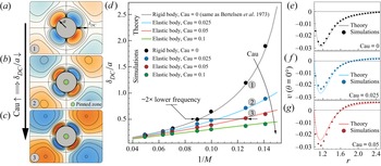
Next, we compare our theory against known analytical results in the rigidity limit (Raney, Corelli & Westervelt Reference Raney, Corelli and Westervelt1954; Bertelsen et al. Reference Bertelsen, Svardal and Tjøtta1973), and direct numerical simulations performed using remeshed vortex methods (Bhosale et al. Reference Bhosale, Parthasarathy and Gazzola2021a; Gazzola, Van Rees & Koumoutsakos Reference Gazzola, Van Rees and Koumoutsakos2012) (see also the caption of figure 2). For a rigid cylinder ( $\mathrm {Cau} = 0$) oscillating at
 $M \approx 8$, numerical time-averaged Lagrangian streamlines (i.e. Stokes-drift corrected – see supplementary material, § 3 for details) are shown in figure 2(a). We highlight the fourfold symmetry and the presence of a well-defined direct circulation (DC) layer of thickness
 $\delta _{DC}$. Holtsmark et al. (Reference Holtsmark, Johnsen, Sikkeland and Skavlem1954) predict this flow topology, as well as an increase of
 $\delta _{DC}$ with
 $1 / M$ until divergence, at which point the DC layer extends to infinity. This behaviour is recovered by our theory when
 $\mathrm {Cau} = 0$ (i.e.
 $\varLambda = 0$), and by simulations (black line/dots in figure 2d). As the cylinder becomes soft (
 $\mathrm {Cau} > 0$), fourfold symmetry is preserved (
 $\sin 2 \theta$ in (3.20)), but
 $\delta _{DC}$ contracts on account of the elastic term
 $\varLambda \neq 0$. This is confirmed by simulations across a range of
 $\mathrm {Cau}$, as seen in figure 2(b–d). An intuitive argument for this effect may be the following. If the cylinder is soft (
 $\mathrm {Cau} > 0$), its surface deforms and the associated deformation velocities feed back into the flow, acting as an additional source of inertia. As a result, the flow effectively ‘sees’ a greater
 $M$ relative to the rigid case, hence a decrease of DC layer thickness with elasticity (
 $\mathrm {Cau}$). This further implies that an elastic body can access the streaming flow configurations of rigid objects with significantly lower oscillation frequencies. This can be seen in figure 2(d), where, for example at
 $\mathrm {Cau} = 0.05$, a
 ${\sim }2 \times$ frequency reduction is observed. Additionally, we note that for soft cylinders the divergence of
 $\delta _{DC}$ with decreasing
 $M$ is still expected as for rigid counterparts, although at lower values of
 $M$. This is because for
 $\mathrm {Cau} > 0$, the rigid body contribution
 $\varTheta (r)$ is the same as in classic streaming and will diverge, with the elasticity contribution
 $\varLambda (r)$ only shifting the curve (see supplementary material, § 7 for details). We conclude our validation by reporting in figure 2(e–g) theoretical and simulated radially varying, time-averaged velocities
 $|\langle v \rangle |$ at
 $\theta = 0^{\circ }$, noting close agreement. For a detailed analysis surrounding the effect of inertia (
 $M$) and elasticity (Cau) on velocity magnitudes (flow strength), the reader is referred to § 4 of supplementary material.
Effect of elasticity on streaming flow. (a–c) Time-averaged Lagrangian (i.e. Stokes-drift corrected – see supplementary material, § 3 for details) streamline patterns (blue/orange represent clockwise/anticlockwise rotating regions) depicting streaming response at  $M \approx 8$ with increasing softness
 $\mathrm {Cau}$: (a) rigid limit (
 $\mathrm {Cau} = 0$), (b)
 $\mathrm {Cau} = 0.025$ and (c)
 $\mathrm {Cau} = 0.05$. Non-dimensional radius of the pinned zone (green cylinder) is set at
 $\zeta = 0.2$ throughout the study. For effects of
 $\zeta$ variation on streaming, refer to supplementary material, § 5. (d) Normalized DC layer thickness
 $\delta _{DC} / a$ vs inverse of Womersley number (
 $1 / M$) from theory and simulations, for varying body elasticity
 $\mathrm {Cau}$. The DC layer is the innermost recirculation zone (a–c). Its extent (finite or infinite thickness) and flow velocities characterize streaming. Its robust nature and high flow gradients and curvatures render the DC layer useful for trapping, filtration or chemical mixing. (e–g) Radial decay of velocity magnitude along
 $\theta = 0^{\circ }$ from theory and simulations, with increasing softness
 $\mathrm {Cau}$. Experimental parameter values equivalent to the range of
 $M$ and
 $\mathrm {Cau}$ considered here can be found in supplementary material, § 6, revealing practical viability in association with soft tissue or common polymeric materials. Simulations are performed using a remeshed vortex methodology (Gazzola et al. Reference Gazzola, Chatelain, Van Rees and Koumoutsakos2011; Bhosale, Parthasarathy & Gazzola Reference Bhosale, Parthasarathy and Gazzola2021a) that accurately solves the vorticity–velocity formulation of the Navier–Stokes equations. The flow domain is discretized as particles for vorticity advection. The vorticity carried by particles is then interpolated on a regular mesh for the evaluation of all other terms. Within this framework, the rigid cylinder is modelled as a density matched (
 $\rho _f = \rho _e = 1$) Brinkmann solid, while the elastic cylinder is modelled as a density matched viscoelastic Kelvin–Voigt solid with shear modulus
 $G$. Deformations are tracked using an inverse-map technique (Kamrin & Nave Reference Kamrin and Nave2009; Kamrin, Rycroft & Nave Reference Kamrin, Rycroft and Nave2012). The pinned zone is modelled as a Brinkmann solid. The parametric values for the far-field motion
 $V(t) = V_0 \cos \omega t$ with characteristic velocity
 $V_0 = \epsilon a \omega$, are
 $\epsilon = 0.1$ and
 $\omega = 32 {\rm \pi}$. Parametric values of fluid dynamic viscosity
 $\mu _f$, oscillation frequency
 $\omega$ and shear modulus
 $G$ are determined based on the Womersley number
 $M = a \sqrt {\rho _f \omega / \mu _f}$, and Cauchy number
 $\mathrm {Cau} = \epsilon \rho _f a^{2} \omega ^{2} / G$. Additional simulation details: domain
 $[0, 1]^{2}$, uniform grid spacing
 $h=1 / 1024$, penalization factor
 $\lambda = 1\times 10^{4}$, mollification length
 $\epsilon _{moll} = 2 \sqrt {2} h$, Lagrangian Courant–Friedrichs–Lewy number LCFL =
 $0.1$. These values are used throughout the text, unless stated otherwise. Refer to Gazzola et al. (Reference Gazzola, Chatelain, Van Rees and Koumoutsakos2011) and Bhosale et al. (Reference Bhosale, Parthasarathy and Gazzola2021a) for details on these parameters.

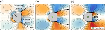
Finally, we demonstrate how gained theoretical intuition extends to geometries of multiple curvatures. We consider the shape of figure 3, previously designed (Bhosale et al. Reference Bhosale, Parthasarathy and Gazzola2020) to attain streaming flows favourable to particle transport (Parthasarathy et al. Reference Parthasarathy, Chan and Gazzola2019) and separation (Bhosale et al. Reference Bhosale, Vishwanathan, Parthasarathy, Juarez and Gazzola2021b). Both applications rely on the presence of flanking and rear vortices, and performance is improved by strengthening the vortices via increasing oscillation frequencies (Bhosale et al. Reference Bhosale, Parthasarathy and Gazzola2020). Figure 3 shows how the same process can alternatively be achieved by increasing softness only. As a result, the same flow topologies of Bhosale et al. (Reference Bhosale, Parthasarathy and Gazzola2020) are obtained in figure 3 for frequencies  ${\sim }4 \times$ lower.
Extension of compliance-induced streaming to generalised, multiple curvature bodies. Time-averaged Eulerian flow topologies obtained from simulations for a bullet – formed by hybridizing a circle of radius  $a$ with a square of side length
 $2a$ – at
 $M \approx 8$, with varying body elasticity
 $\mathrm {Cau}$: (a) rigid limit
 $\mathrm {Cau} = 0$, (b)
 $\mathrm {Cau} = 0.05$ and (c)
 $\mathrm {Cau} = 0.1$. Increasing body softness results in contraction and strengthening of the rear DC vortex on the square side, consistent with our theoretical insights.

5. Conclusion
In summary, we derived a viscous streaming theory for the case of an elastic cylinder, and validated it computationally. Our study reveals an additional, tunable mode of streaming, accessible through material compliance and available even in Stokes flow. We demonstrate its use for flow control in the case of a previously designed streaming body of multiple curvatures, to illustrate application potential in microfluidics or microrobotics, in conjunction with the use of elastomeric or biological materials. Further, the fact that compliance enables streaming effects at frequencies significantly lower than rigid bodies supports the hypothesis that biological creatures, speculated to operate at the edge of viscous streaming viability, may instead take full advantage of it thanks to their softness.
Supplementary material
Supplementary material is available at https://doi.org/10.1017/jfm.2022.525.
Acknowledgements
We thank S. Agarwal, S. Hilgenfeldt and M. Matalon for helpful discussions over the course of this work.
Funding
The authors acknowledge support by the National Science Foundation under NSF CAREER grant no. CBET-1846752 (MG). This work used the Extreme Science and Engineering Discovery Environment (XSEDE) (Towns et al. Reference Towns2014) Stampede2, supported by National Science Foundation grant no. ACI-1548562, at the Texas Advanced Computing Center (TACC) through allocation TG-MCB190004.
Declaration of interests
The authors report no conflict of interest.