Recent discovery of a catalytic synthesis of a three-dimensional (3D)-polymerized ultrahard fullerite[Reference Popov, Mordkovich, Perfilov, Kirichenko, Kulnitskiy, Perezhogin and Blank1] opens wide opportunities for a practical use of the fullerene-based class of materials. Indeed, a presence of a catalyst (carbon disulfide, CS2) decreases the synthesis pressure of ultrahard fullerite by a factor of 3 at room temperature (from 18 to 6–7 GPa). Contrary to CS2, the solvents such as m-xylene have a negligible effect on C60 transformations. The sequence and pressure of phase transitions in the solvated C60/m-xylene and desolvated C60 samples are the same,[Reference Yao, Cui, Xiao, Chen, Cui, Liu, Cui, Zou, Liu and Sundqvist2] whereas a long-range periodic structure can be produced from the solvated C60/m-xylene,[Reference Wang, Liu, Li, Yang, Ding, Sinogeikin, Meng, Liu, Zeng and Mao3] contrary to the samples of pure C60 loaded under the same conditions.
Mechanical properties of ultrahard fullerite synthesized with the CS2 catalyst are identical to ultrahard fullerite synthesized from pure C60. In both cases, the samples plough diamond during the sample rotation in a shear diamond anvil cell (SDAC) and their bulk module is 585 GPa.[Reference Popov, Mordkovich, Perfilov, Kirichenko, Kulnitskiy, Perezhogin and Blank1] A sequence of phase transitions preceding the ultrahard phase is also the same in both cases. All the above-mentioned experiments were performed at room temperature, and we could expect further decreasing of the synthesis pressure of the fullerite phases upon heating in the presence of the catalyst. For example, a temperature increasing to 1100 K decreases the synthesis pressure of the ultrahard fullerite from 18 to 13 GPa (without the catalyst).[Reference Blank, Buga, Serebryanaya, Dubitsky, Mavrin, Popov, Bagramov, Prokhorov, Sulynov, Kulnitskiy and Tatyanin4]
Meanwhile, a direct scaling of high pressure–temperature diagram of non-catalytic synthesis conditions of different fullerite phases and their derivatives to a catalytic one could not be correct. The main obstacle of the scaling is the C60 cluster thermal stability. The C60 stability at temperatures above 800–900 K depends both on temperature, pressure, and time of heating.[Reference Popov, Gayazov, Khadzhiyskiy, Medvedev, Krivtsun, Kirichenko, Kulnitskiy, Perezhogin, Tyukalova and Blank5] An increase in temperature decreases the phase transition pressure but raises the C60 disintegration probability. The growing pressure increases the temperature stability of C60. Thus, decreasing a heating–cooling cycle time to 0.1 μs permits to increase the maximal temperature of the fullerite sample to 2700 K under the 8–10 GPa pressure on conditions that C60 are still surviving.[Reference Popov, Gayazov, Khadzhiyskiy, Medvedev, Krivtsun, Kirichenko, Kulnitskiy, Perezhogin, Tyukalova and Blank5] Such a short heating time can be realized for thin (about 20 μm) samples compressed in a SDAC, while the heating–cooling cycle time is about 1 min for the relatively big samples (with typical size of 1–10 cm).
A loss of a ball-type construction of C60 upon heating does not mean a critical loss of mechanical properties. There are three main groups of fullerite phases and their derivatives having unique mechanical properties and which are targets of the catalytic transformations of C60. An ultrahard fullerite group covers different phases synthesized from C60 with a 200–300 GPa hardness and a 500–1000 GPa bulk modulus exceeding those of a diamond (150 and 443 GPa, accordingly).[Reference Blank, Popov, Pivovarov, Lvova, Gogolinsky and Reshetov6, Reference Popov, Kulnitskiy, Blank, Sarin and Nebel7] Meantime, the ultrahard phases synthesized at 900–1300 K are 3D-polymerized C60 having a distorted face-centered cubic (fcc)-lattice structure, while the one synthesized at 1800 K has an onion-type structure formed from the damaged molecules.[Reference Popov, Kulnitskiy, Blank, Sarin and Nebel7] Decreasing the synthesis pressure to 9 GPa at 900–1200 K leads to a formation of superhard phases which are also 3D-polymerized C60 having a distorted fcc-lattice type of the structure.[Reference Blank, Buga, Serebryanaya, Dubitsky, Mavrin, Popov, Bagramov, Prokhorov, Sulynov, Kulnitskiy and Tatyanin4] Decreasing the synthesis pressure to 8 GPa at 1200–1800 K leads to the synthesis of disordered phases formed from the damaged molecules with a 30–40 GPa hardness.[Reference Blank, Denisov, Ivlev, Mavrin, Serebryanaya, Dubitsky, Sulynov, Popov, Lvova, Buga and Kremkova8] In spite of moderate hardness, the latter group reveals an anomalous elastic recovery effect.
In the present work, we report a hard derivative of fullerite composed from the damaged molecules which was synthesized at a 0.5–4 GPa pressure and a 1100–1500 K temperature. To obtain the homogeneous crack-free samples, we add a powder of B4C in the fullerite samples (a mean grain size of B4C is about 100 nm). A main reason of adding B4C is the following. The initial fullerene C60 (molecular crystal) density is 1.7 g/cm3, whereas the density of the synthesized derivative of fullerite is about 2 g/cm3. Consequently, a volume jump is 15% during the synthesis which leads to some essential deformations of the sample and an appearance of numerous cracks. The addition of 50 wt% B4C decreases the volume jump in the composite sample. As a result, the crack-free cylindrical samples of the B4C–fullerite derivatives composite with a 20 mm diameter and a 5 mm height were synthesized. Properties of the B4C–fullerite derivatives composite samples are unique: maximal flexural stress is 550 MPa, compressive strength is 2250 MPa, and density is 2.2 g/cm3, hardness is 28 GPa, the elastic recovery is 98%.
The samples were synthesized using a toroid-type cell.[Reference Blank, Buga, Serebryanaya, Dubitsky, Mavrin, Popov, Bagramov, Prokhorov, Sulynov, Kulnitskiy and Tatyanin4] The catalyst (5–10 wt% of CS2) was added to C60 or to a mixture of C60 and B4C (we used 50% weight proportion of the mixture components). The purity of both fullerene C60 and CS2 used in the study was better than 99.9%.
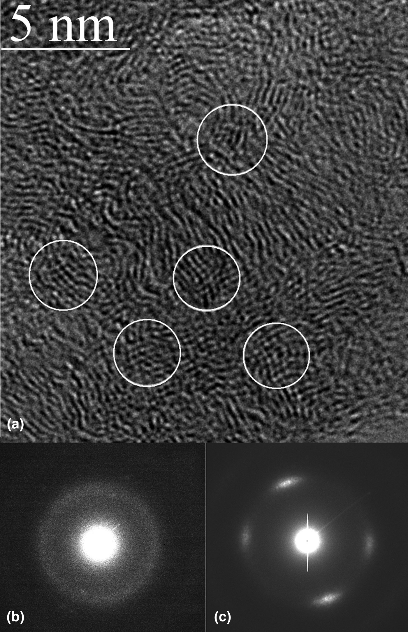
Figure 1(a) shows the typical structure of the fullerite derivatives sample synthesized from CS2+C60. The structures of samples synthesized from CS2+C60 and CS2+C60+B4C are identical. The circles indicate the intersecting fringes which compose an angle of 70°. The interplanar distances corresponding to them vary within the range 0.32–0.36 nm. Usually the diffraction pattern represents itself as a practically uniformly illuminated circle with the reciprocal radius corresponding to the above-mentioned distance [Fig. 1(b)]. Some relatively large areas yielding the diffraction pattern as the one shown in Fig. 1(c) were observed as well. A similar structure was observed in Ref. Reference Blank, Tatyanin and Kulnitskiy9, where C60 was treated under the pressure of 9.5 GPa and a 670–770 K temperature. The difference between those structures and the present sample is that the diffraction pattern shown in Fig. 1(c) appears at relatively large areas of the sample in Ref. Reference Blank, Tatyanin and Kulnitskiy9, while in the present work it remains unchanged at rather small areas, and it is observed not so often. Therefore, we observe a material with a larger degree of fragmentation, compared with that observed in Ref. Reference Blank, Tatyanin and Kulnitskiy9. In the sample in the present study, unlike in the previous one, the sulfur was added, and the treatment pressure was decreased. To all appearances, the sample fragmentation is connected with the sulfur addition. The sulfur content can be assessed as 1–2 at. % by the electron dispersive spectroscopy (EDS) spectra. Thus, only small amount of sulfur remains in the sample. According to our data, this sulfur rest presents as impurities in the sample, since not all the fragments of the sample yield sulfur peak in EDS. As it is known, the sulfur atoms can serve as a connecting agent between the molecules of C60. At the first stage they embed into the material and connect the molecules, but afterwards it can lead to the destruction of C60. The formation of such a structure is preceded by the formation of chains along the 〈110〉-direction, consisting of C60.[Reference Blank, Kulnitskiy, Dubitsky and Alexandrou10] A further increase in pressure leads to further deformation of the chains and the formation of the above-mentioned structures, the appearance mechanism of which still cannot be fully explained. To all appearances, the role of sulfur is to penetrate into the polymerized chains and to destroy the molecules, which leads to considerable fragmentation of the sample. Therefore, we treat sulfur as a catalyst, since only minor amount of it eventually remains in the sample, and does not change the sample structure.
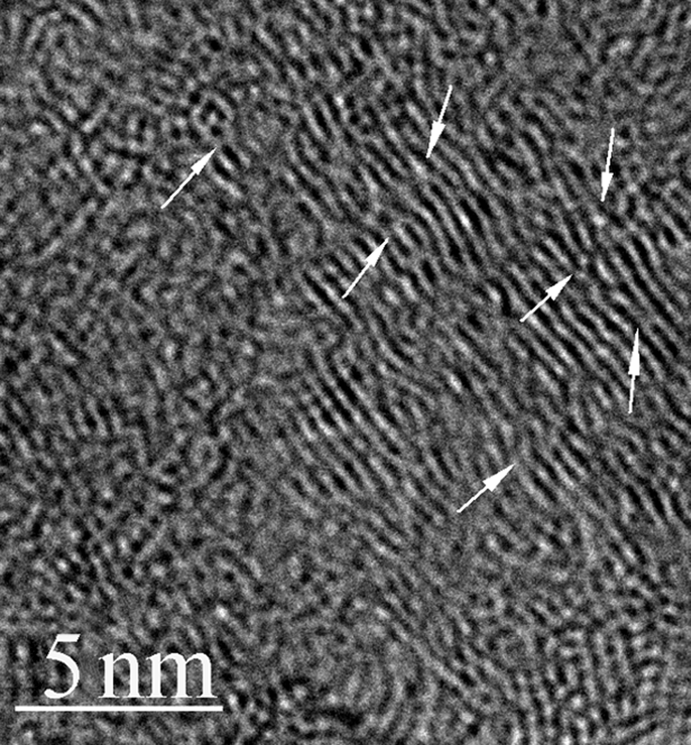
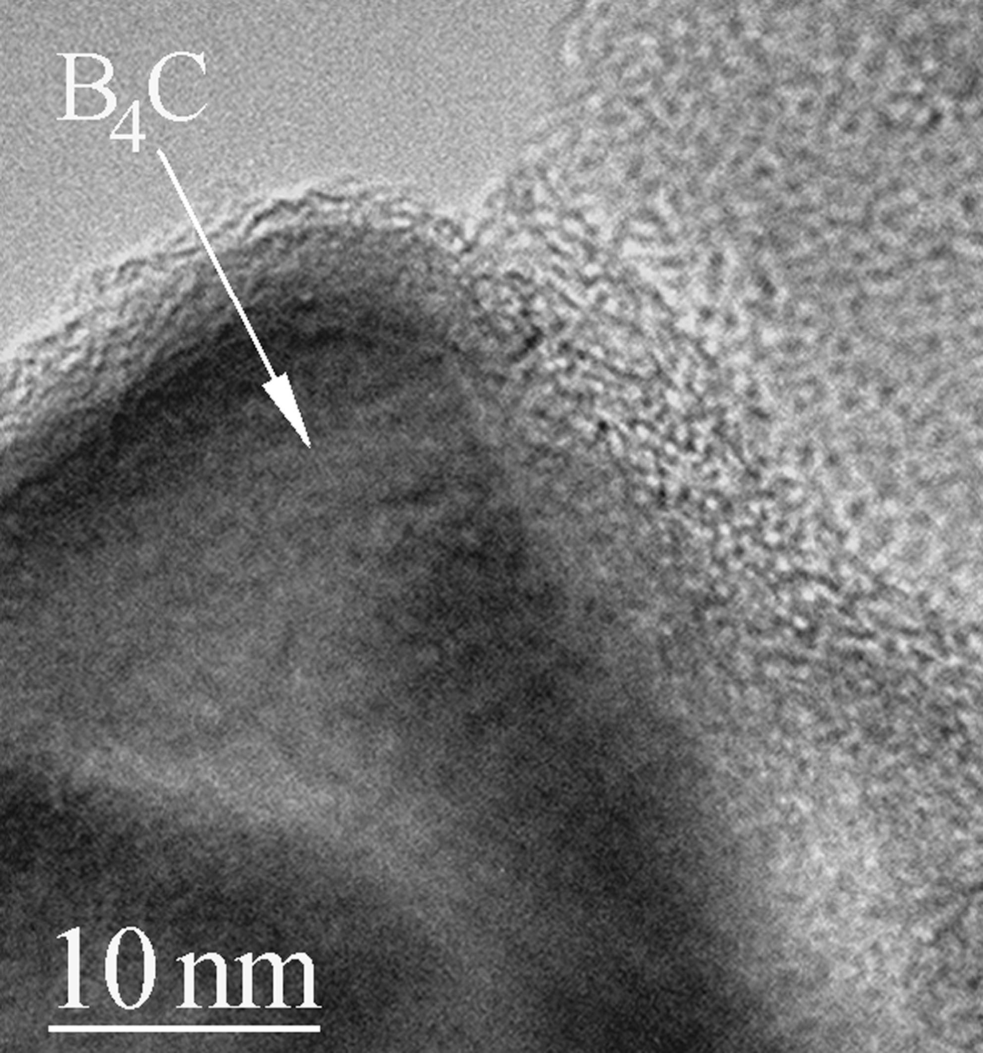
Figure 2 shows the points of fringes intersection. In these points, the stacking of the curved graphene layers is interrupted. Such defects were discussed in Ref. Reference Balaban, Klein and Folden11 and observed in Ref. Reference Blank, Denisov, Kirichenko, Kulnitskiy, Martyushov, Mavrin and Perezhogin12 where they were presented in the spherical objects. Such a defect is generated by the rupture of several spheres (or layers) and the subsequent relative displacement of their parts. Bonding of ruptured spheres can occur in this case because of the formation of sp 3-bonds.[Reference Balaban, Klein and Folden11] We also observed some boron carbide particles in the sample. Usually they were covered by the amorphous carbon shell (Fig. 3). Also, we observed the closed round objects on their surface. Basing on the analysis performed in Ref. Reference Goel, Howard and Sande13, we conclude that these objects are the C60 fullerenes.
A high-resolution image of the specimen synthesized from CS2+C60. (a) Circles indicate the intersecting fringes composing an angle of approximately 70°. The interplanar distances vary within the range 0.32–0.36 nm; (b) a typical diffraction pattern: an almost uniformly illuminated circle corresponding to the interplanar distances of the fringes in (a). Sometimes we observed some relatively large areas yielding the diffraction pattern shown in (c).

The points of fringes intersection (marked by arrows). In these points, the stacking of the curved graphene layers is interrupted representing the defects. These features are observed both for samples synthesized from CS2+C60 and CS2+C60+B4C.
Boron carbide particles in the sample covered by the amorphous carbon shell (CS2+C60+B4C sample).
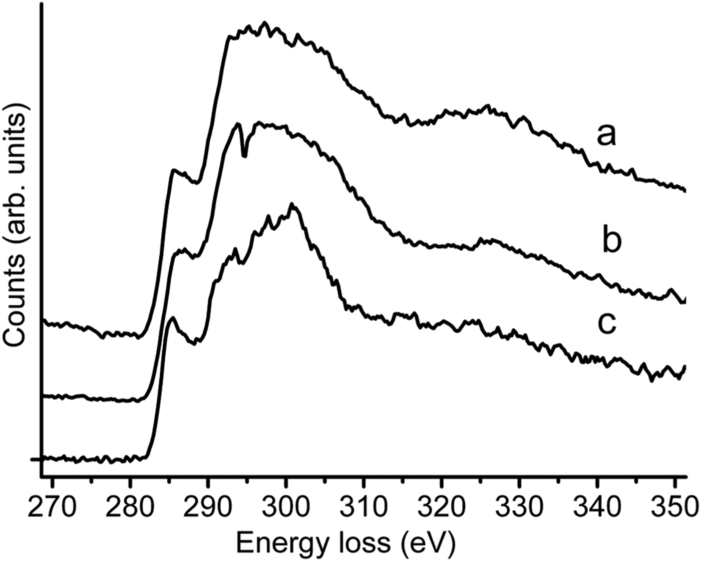
Figure 4 shows two electron energy loss spectroscopy (EELS) spectra (a, b) taken from different areas of the sample (synthesized from CS2+C60) in an energy loss range corresponding to the K-edge of carbon. Features of the K-edge in these spectra allow us to make decisions on the sample structure. The peaks at 284 eV and at approximately 292 eV correspond to the π–π* and σ–σ* transitions in graphite.[Reference Suenaga, Sandre, Colliex, Pickard, Kataura and Iijima14] These peaks are also present in fullerene spectrum [Fig. 4(c)][Reference Hansen, Fallon and Krätschmer15]; however, the peak at 284 eV has additional high-resolution features, and the peak at 292 eV is not the biggest one (as it should be in graphite): the biggest peak is located at approximately 300 eV. We do not possess high enough resolution of our instrument to resolve all these features sharply; however, in our sample, the peak at 284 eV is relatively broad and sometimes jagged (compared with analogous peaks in graphite and amorphous carbon). We interpret these features as ones testifying the presence of fullerenes or their fragments in the sample. The fact that the main peak [some eV to the left and to the right from 300 eV, an especially sharp peak in Fig. 4(b)] is also jagged testifies our interpretation too. However, in our spectra the relative weights of the peaks are different from those in untreated fullerene spectrum. We believe that in spite the fact that C60 molecules (or their fragments) are present in the sample; its structure is essentially different from that of fullerite. Apart from this, the spectra taken from different (but located not far away from one another) areas of the sample are also different. Therefore, the sample composition is rather non-uniform. The C60 molecule has no 4- or 6-fold axes. Consequently, a long-term periodicity of a crystal lattice could not be possible for the covalently bonded C60 molecules in three dimensions.
EELS spectra taken from different areas of the sample in a spectral range covering the K-edge of carbon (see the text for details): (a, b) sample synthesized from CS2+C60), (c) Initial C60.
The x-ray photoelectron spectroscopy (XPS) analysis of the pristine fullerene C60 and the P–T-treated sample (C60+CS2) showed that C60 C1s line has changed insignificantly after treatment. There was a slight broadening of the C1s spectrum associated with the appearance of the adventitious carbon and C–O bonds at the surface that indirectly indicates the sp 3-bonds formation. The value of the sp 3 fraction determined by the method based on the analysis of C1s core line and plasmon loss spectra, which showed good correlation for transformation of fullerites,[Reference Parkhomenko, Skryleva, Sanakoev, Serebryanaya, Blank, Buga, Dubitsky and Kulnitskiy16] was approximately 10%. Such low contents of the sp 3 fraction characterize the processes of polymerization and correspond to the above-described structure.
The samples synthesized from C60+CS2 (without B4C) have enough crack-free parts for hardness tests. The nanoindenter tests (we used a NanoScan 3D system) show a 98% elastic recovery effect at maximal indenter loads in the range of 2–100 mN. Consequently, indentation tests (both Vickers and Knoop) cannot be effective in this case.
In comparison with the indentation method, a sclerometry (a scratch test) procedure implies a large plastic deformation and decreases the elastic recovery effect.[Reference Blank, Buga, Serebryanaya, Dubitsky, Mavrin, Popov, Bagramov, Prokhorov, Sulynov, Kulnitskiy and Tatyanin4, Reference Blank, Popov, Pivovarov, Lvova, Gogolinsky and Reshetov6–Reference Blank, Denisov, Ivlev, Mavrin, Serebryanaya, Dubitsky, Sulynov, Popov, Lvova, Buga and Kremkova8, Reference Blank, Popov, Pivovarov, Lvova and Terentev17] The sclerometry tests were made using a Vickers indenter (scratching ‘edge forward’) at indenter loads P in the range of 0.49–1.96 N. Scratch widths b were measured using an optic microscope [scratches made at P = 1.96 N, Fig. 5(a)] and a scanning electron microscope (SEM). In Fig. 5(b), the P/b 2 values [hardness H in the scratch tests made by Vickers indenter is calculated as H = (P/b 2)4cos22°] are plotted against b. Figure 5(b) demonstrates the essential elastic recovery effect, and we are not aware that we reached real hardness values even at the indenter load maximal possible in our experiments P = 1.96 N (appropriate b = 8.5 μm and H = 100 GPa). Similar [to Fig. 5(b)] dependences were observed in Ref. Reference Sumiya, Ishida, Arimoto and Harano18 for indentation tests of nano-polycrystalline cBN. Nevertheless in our case the indentations made by Vickers or Knoop indenter are hardly visible and a direct comparison is not possible. In any case, the hardness is between the one of sapphire and that of diamond: the sample scratches sapphire (H = 23 GPa) and does not scratch a diamond face (100) (H = 115–140 GPa[Reference Blank, Popov, Pivovarov, Lvova and Terentev17]).
Results of the sclerometry tests of the samples synthesized from CS2+C60. (a) a scratch made by the Vickers indenter at the indenter load P = 1.96 N on the sample synthesized from C60 without B4C. (b) Values of P/b 2 are plotted against the scratch width b; the dependence demonstrates the essential elastic recovery effect.
The elastic recovery effect for the samples synthesized from the mixture of C60 and B4C is not as high as in the previous case. The indentations are visible at loads above 4.91 N, and the hardness H = 28 GPa was measured at the indenter loads in the range from 9.81 to 29.4 N.
The maximal flexural stress (measured in the three-point bending tests using an Instron 5982 testing system) of C60 + B4C samples is 550 MPa, compressive strength is 2250 MPa.
We calculated the elastic moduli of C60 + B4C samples using the measured density of 2.2 g/cm3 and velocities of longitudinal and transverse bulk acoustic waves (measured with a pulse-echo method by laser optoacoustic excitation of ultrasonic pulses with an accuracy of ~1%). The elastic moduli of the samples are as follows: Young's modulus E = 140–150 GPa, bulk modulus K = 80–105 GPa, shear modulus G = 58–63 GPa.
In summary, in the presence of the catalyst, a unique carbon phase composed from the fragments of C60 molecules linked by covalent bonds was synthesized at a relatively low pressure range of 0.5–4 GPa. A composite of the carbon phase with B4C shows simultaneously high hardness, flexural strength, and low density (28 GPa, 550 MPa, and 2.2 g/cm3, accordingly). The carbon phase without B4C shows a 98% elastic recovery effect and has hardness that possibly reaches 100 GPa.
Acknowledgments
We thank Mrs. Solov'eva and Mr. Illich-Svitych for the mechanical tests and Mr. Ivanov for the SEM study of the scratches. This work was supported by the Ministry of Education and Science of the Russian Federation, basic program for the National University of Science and Technology MISiS and grant 14.577.21.0094 (ID project RFMEFI57714X0094); the work was done using the equipment of Joint Research Center ‘Material Science and Metallurgy’ of NUST MISiS.