

1 Introduction
The linear spin-down of a rapidly rotating fluid, when the containing boundary is adjusted by a small amount, is characterised by two distinct transient motions. The primary part which is largely responsible for the spin-down is a quasi-steady geostrophic (QG) flow exterior to any quasi-steady boundary layers. A secondary part is the excitation of inertial waves, which decay either due to boundary layer effects or, if they are of sufficiently short length scale, in the main body of the fluid itself. In our previous paper (Oruba, Soward & Dormy Reference Oruba, Soward and Dormy2017), we investigated spin-down in a cylindrical container, radius  $L$, height
 $H$, rotating rapidly about its axis of symmetry subject to mixed rigid and stress-free boundary conditions. There, we focused on the aspect ratio
 $\ell \equiv L/H=1$ and, because our direct numerical simulations (DNS) revealed little inertial wave activity or more precisely the inertial waves decayed very rapidly (for reasons that will become clearer later) and were hardly visible, we only investigated analytically the aforementioned primary QG-flow part. That study was motivated by the possible application to intense nearly axisymmetric vortices, which develop in geophysical flows, e.g. hurricanes in the atmosphere, and westward-propagating mesoscale eddies that occur throughout most of the World Ocean (Chelton, Schlax & Samelson Reference Chelton, Schlax and Samelson2011) as evidenced by the sea surface height variability. Oscillations, reminiscent of inertial waves, have been observed near the eye of actual tropical cyclones (e.g. Harlow & Stein Reference Harlow and Stein1974; Chen et al. Reference Chen, Lu, Li and Wen2015). The benefits of modelling such objects by isolated structures is well established (see Persing et al. Reference Persing, Montgomery, Smith and McWilliams2015; Oruba, Davidson & Dormy Reference Oruba, Davidson and Dormy2017, Reference Oruba, Davidson and Dormy2018; Atkinson, Davidson & Perry Reference Atkinson, Davidson and Perry2019, and references therein). For those applications the aspect ratio
 $\ell$ ought to be large, and so our previous choice
 $\ell =1$ is clearly not the most appropriate. Indeed, later DNS results for large aspect ratio, namely
 $\ell =10$, have revealed considerable persistent inertial wave activity. The analytic results of § 2 apply to all
 $\ell$, while their numerical predictions are compared with DNS results of § 3 for the largish aforementioned
 $\ell =10$. However, it is only in §§ 4–6 that the analysis is restricted to the limit,
 $\ell \gg 1$ (see (4.5b)) amenable to asymptotic treatment, enabling us to identify the wave mechanisms that operate.
As our work builds upon Oruba et al. (Reference Oruba, Soward and Dormy2017), we only repeat essential details such as the description of the model and needed results. Our cylindrical container is filled with constant density fluid of viscosity  $\unicode[STIX]{x1D708}$ and rotates rigidly with angular velocity
 $\unicode[STIX]{x1D734}$ about its axis of symmetry. That is the frame relative to which our analysis is undertaken and in which the Ekman number is small:
 $$\begin{eqnarray}\displaystyle E=\unicode[STIX]{x1D708}/(H^{2}\unicode[STIX]{x1D6FA})\ll 1. & & \displaystyle\end{eqnarray}$$
Initially, at time  $t^{\dagger }=0$, the fluid itself rotates rigidly at the slightly larger angular velocity
 $Ro\unicode[STIX]{x1D734}$, in which the Rossby number
 $Ro$ is sufficiently small (
 $Ro\ll E^{1/4}$) for linear theory to apply (see Duck & Foster Reference Duck and Foster2001, p. 235). Whereas, the nonlinear development of spin-down and spin-up differ (see, e.g. Calabretto, Denier & Mattner Reference Calabretto, Denier and Mattner2018, and references therein), their linear evolution, which we consider, is mathematically equivalent. Relative to cylindrical polar coordinates,
 $(r^{\dagger },\unicode[STIX]{x1D703}^{\dagger },z^{\dagger })$, the top boundary (
 $r^{\dagger }<L$,
 $z^{\dagger }=H$) and the sidewall (
 $r^{\dagger }=L$,
 $0<z^{\dagger }<H$) are impermeable and stress free. The lower boundary (
 $r^{\dagger }<L$,
 $z^{\dagger }=0$) is rigid. For that reason alone the initial state of relative rigid rotation
 $Ro\unicode[STIX]{x1D734}$ of the fluid cannot persist and the fluid spins down to the final state of no rotation relative to the container as
 $t^{\dagger }\rightarrow \infty$. In order to make our notation relatively compact at an early stage, we use
 $H$ and
 $\unicode[STIX]{x1D6FA}^{-1}$ as our units of length and time, respectively, and introduce
 $$\begin{eqnarray}\displaystyle r^{\dagger }=Hr,\quad z^{\dagger }=Hz,\quad \unicode[STIX]{x1D6FA}t^{\dagger }=t. & & \displaystyle\end{eqnarray}$$
For our unit of relative velocity  $\boldsymbol{v}^{\dagger }$, we adopt the velocity increment
 $RoL\unicode[STIX]{x1D6FA}$ of the initial flow at the outer boundary
 $r^{\dagger }=L$. So, relative to cylindrical components, we set
 $$\begin{eqnarray}\displaystyle \boldsymbol{v}^{\dagger }=RoL\unicode[STIX]{x1D6FA}\boldsymbol{v},\quad \boldsymbol{v}=[u,v,w] & & \displaystyle\end{eqnarray}$$
and refer to  $[u,v]$ and
 $w$ as the horizontal and axial components of velocity, respectively. The meridional flow
 $[u,w]$ may be described by a streamfunction
 $r\unicode[STIX]{x1D712}$ as
 $$\begin{eqnarray}\displaystyle u=-{\displaystyle \frac{\unicode[STIX]{x2202}\unicode[STIX]{x1D712}}{\unicode[STIX]{x2202}z}},\quad w={\displaystyle \frac{1}{r}}{\displaystyle \frac{\unicode[STIX]{x2202}}{\unicode[STIX]{x2202}r}}(r\unicode[STIX]{x1D712}). & & \displaystyle\end{eqnarray}$$
Owing to the impulsive nature of the transient spin-down, the classical temporally spreading diffusion width
 $$\begin{eqnarray}\displaystyle \unicode[STIX]{x1D6E5}^{\dagger }=\sqrt{\unicode[STIX]{x1D708}t^{\dagger }}=H\unicode[STIX]{x1D6E5},\quad \unicode[STIX]{x1D6E5}(t)=\sqrt{Et} & & \displaystyle\end{eqnarray}$$
provides a useful measure for defining all boundary-layer widths, both horizontal and vertical.
1.1 Spin-down between two unbounded parallel plates
When the flow is unbounded in the radial extent the solution to the linear spin-down problem has the similarity form
 $$\begin{eqnarray}\displaystyle [u,v]=(r/\ell )[\mathfrak{u},\mathfrak{v}](z,t),\quad w=(1/\ell )\mathfrak{w}(z,t), & & \displaystyle\end{eqnarray}$$
 $$\begin{eqnarray}\displaystyle \unicode[STIX]{x1D712}=(r/\ell )\unicode[STIX]{x1D6EF}(z,t),\quad \unicode[STIX]{x1D6EF}={\textstyle \frac{1}{2}}\mathfrak{w}(z,t)=\int _{z}^{1}\mathfrak{u}\,\text{d}z, & & \displaystyle\end{eqnarray}$$
i.e.  $\mathfrak{u}=-\unicode[STIX]{x2202}\unicode[STIX]{x1D6EF}/\unicode[STIX]{x2202}z$, by mass continuity. Here
 $[\mathfrak{u},\mathfrak{v}]$ solves
 $$\begin{eqnarray}\displaystyle \unicode[STIX]{x2202}_{t}\mathfrak{u}-2(\mathfrak{v}-\mathfrak{g})=E\unicode[STIX]{x2202}_{z}^{2}\mathfrak{u},\quad \unicode[STIX]{x2202}_{t}\mathfrak{v}+2\mathfrak{u}=E\unicode[STIX]{x2202}_{z}^{2}\mathfrak{v}, & & \displaystyle\end{eqnarray}$$
where  $\mathfrak{g}(t)$ (independent of
 $z$) is the suitably non-dimensionalised radial pressure gradient. It is chosen such that the total radial volume flux proportional to
 $\unicode[STIX]{x1D6EF}(0,t)=\langle \mathfrak{u}\rangle =0$, where
 $$\begin{eqnarray}\displaystyle \langle \bullet \rangle =\int _{0}^{1}\bullet \text{d}z & & \displaystyle\end{eqnarray}$$
is the  $z$-average. Equation (1.6) are solved subject to the boundary conditions
 $[\mathfrak{u},\mathfrak{v}]=[0,0]$ at
 $z=0$ (rigid) and
 $[\unicode[STIX]{x2202}_{z}\mathfrak{u},\unicode[STIX]{x2202}_{z}\mathfrak{v}]=[0,0]$ at
 $z=1$ (stress free) for
 $t>0$ and, of course,
 $\langle \mathfrak{u}\rangle =0$ which by (1.6a) implies
 $\mathfrak{g}=\langle \mathfrak{v}\rangle -{\textstyle \frac{1}{2}}E\unicode[STIX]{x2202}_{z}\mathfrak{u}|_{z=0}$. The initial condition is
 $[\mathfrak{u},\mathfrak{v}]=[0,1]$ everywhere at
 $t=0$.
We identify the primary part of the flow, largely responsible for the spin-down, namely a quasi-steady geostrophic QG-flow exterior to a quasi-steady Ekman layer adjacent to the rigid boundary  $z=0$ in § 1.1.1. Then, in § 1.1.2, we outline the nature of the remaining transient motion.
1.1.1 The quasi-geostrophic QG-flow
In the mainstream exterior to the Ekman layer, the  $z$-independent horizontal components of the primary QG-velocity
 $[\overline{u}_{QG},\overline{v}_{QG}]=(r/\ell )[\overline{\mathfrak{u}}_{QG},\overline{\mathfrak{v}}_{QG}]$ are described by
 $$\begin{eqnarray}\displaystyle [\overline{\mathfrak{u}}_{QG},\overline{\mathfrak{v}}_{QG}](t)=\overline{\mathfrak{v}}_{QG}[{\textstyle \frac{1}{2}}Q,1],\quad Q=E^{1/2}\unicode[STIX]{x1D70E}. & & \displaystyle\end{eqnarray}$$
Motion is dominated by the azimuthal velocity  $\overline{v}_{QG}=(r/\ell )\overline{\mathfrak{v}}_{QG}$, where
 $$\begin{eqnarray}\displaystyle \overline{\mathfrak{v}}_{QG}(t)=\unicode[STIX]{x1D705}\mathfrak{E}(t),\quad \mathfrak{E}(t)=\exp (-Qt). & & \displaystyle\end{eqnarray}$$
The constants  $\unicode[STIX]{x1D705}$ and
 $\unicode[STIX]{x1D70E}$ are both close to unity and have expansions:
 $$\begin{eqnarray}\displaystyle \unicode[STIX]{x1D705}=1+{\textstyle \frac{1}{4}}E^{1/2}+O(E),\quad \unicode[STIX]{x1D70E}=1+{\textstyle \frac{3}{4}}E^{1/2}+O(E) & & \displaystyle\end{eqnarray}$$
(see Oruba et al. Reference Oruba, Soward and Dormy2017, equations (1.3a–c)). The streamfunction  $\overline{\unicode[STIX]{x1D712}}_{QG}=(r/\ell )\overline{\unicode[STIX]{x1D6EF}}_{QG}(z,t)$ (linear in
 $z$) has
 $$\begin{eqnarray}\displaystyle \overline{\unicode[STIX]{x1D6EF}}_{QG}={\textstyle \frac{1}{2}}\overline{\mathfrak{w}}_{QG}(z,t)=(1-z)\overline{\mathfrak{u}}_{QG}={\textstyle \frac{1}{2}}Q(1-z)\overline{\mathfrak{v}}_{QG}. & & \displaystyle\end{eqnarray}$$
The non-zero value  $\overline{\unicode[STIX]{x1D6EF}}_{QG}(0,t)={\textstyle \frac{1}{2}}Q\overline{\mathfrak{v}}_{QG}(t)$, corresponding to
 $\overline{\mathfrak{w}}_{QG}(0,t)=2\overline{\mathfrak{u}}_{QG}(t)$, results from the outflow from the Ekman layer, in which the horizontal velocity is
 $[u_{E},v_{E}]=(r/\ell )[\mathfrak{u}_{E},\mathfrak{v}_{E}]$ with
 $$\begin{eqnarray}\displaystyle [\mathfrak{u}_{E},\mathfrak{v}_{E}]=-\overline{\mathfrak{v}}_{QG}[\sin (E^{-1/2}z),\cos (E^{-1/2}z)]\exp (-E^{-1/2}z). & & \displaystyle\end{eqnarray}$$
Finally, the composite horizontal velocity  $[u,v]=(r/\ell )[\mathfrak{u},\mathfrak{v}]$ is the sum
 $$\begin{eqnarray}\displaystyle [\mathfrak{u},\mathfrak{v}]=[\overline{\mathfrak{u}}_{QG},\overline{\mathfrak{v}}_{QG}]+[\mathfrak{u}_{E},\mathfrak{v}_{E}]. & & \displaystyle\end{eqnarray}$$
The azimuthal fluid flux deficit  $\langle v(r,z,t)\rangle -\overline{v}_{QG}(r,t)$ (
 $=(\unicode[STIX]{x1D707}-1)\overline{v}_{QG}(r,t)$, say, but see (1.11) below) is important for our interpretation of the DNS. For although
 $\overline{v}_{QG}(r,t)$ is well defined in the limit
 $E\downarrow 0$, it is not easily determined unambiguously from the numerics at finite
 $E$. Nevertheless, we can readily calculate
 $\langle v\rangle$ and from it we may extract
 $$\begin{eqnarray}\displaystyle \overline{v}_{QG}=\unicode[STIX]{x1D707}^{-1}\langle v\rangle ,\quad \text{where }\unicode[STIX]{x1D707}=1-{\textstyle \frac{1}{2}}E^{1/2}+O(E), & & \displaystyle\end{eqnarray}$$
which is the asymptotic prediction encapsulated by equation (2.20) of Oruba et al. (Reference Oruba, Soward and Dormy2017). The result (1.11a) not only applies to the particular rigid rotation flow (1.8c) but also to any QG-flow  $\overline{v}_{QG}(r,t)$ with arbitrary
 $r$-dependence, which is dominated by the decay factor
 $\exp (-E^{1/2}\unicode[STIX]{x1D70E}t)$, as in (1.8d), while possibly evolving on the longer lateral diffusion time scale, as we will now explain.
The main thrust of Oruba et al. (Reference Oruba, Soward and Dormy2017) was to elucidate how the laterally unbounded QG-flow (1.8) is modified by the outer sidewall at  $r=\ell$ (
 $r^{\dagger }=L$). There two boundary layers form whose widths
 $\unicode[STIX]{x1D6E5}(t)$ (see (1.4b)) evolve by lateral viscous diffusion. One develops into the quasi-steady ageostrophic
 $E^{1/3}$-Stewartson layer of width
 $\unicode[STIX]{x1D6E5}(t_{S})=\unicode[STIX]{x1D6E5}_{S}=E^{1/3}$, which forms on the time scale
 $t_{S}=E^{-1/3}$. The other, importantly QG, spreads indefinitely filling the container when
 $\unicode[STIX]{x1D6E5}(t_{\ell })=\ell$ at time
 $t_{\ell }=\ell ^{2}E^{-1}$. So although (1.8) provides a valid description of the QG-motion on the spin-down time scale
 $t_{sd}=E^{-1/2}$ (see (1.8b,d,e)), its radial dependence is more complicated on the longer lateral diffusion time scale
 $t_{\ell }=\ell ^{2}E^{-1}$. The temporal evolution of the QG-flow
 $\overline{v}_{QG}(r,t)$ is sensitive to whether or not the boundary
 $r=\ell$ is stress free as in Oruba et al. (Reference Oruba, Soward and Dormy2017) or rigid as in Greenspan & Howard (Reference Greenspan and Howard1963). However, here we will filter out any QG-motion, ignore the ageostrophic
 $E^{1/3}$-Stewartson layer (discussed at length in Oruba et al. Reference Oruba, Soward and Dormy2017) and, for that matter, the Ekman
 $E^{1/2}\times E^{1/2}$ corner regions, which are largely passive and have vanishing influence on the flow elsewhere as
 $E\rightarrow 0$. Subject to those restrictions we will only investigate the remaining wave part. With that proviso our study applies equally to both the stress-free (Oruba et al. Reference Oruba, Soward and Dormy2017) and rigid (Greenspan & Howard Reference Greenspan and Howard1963)
 $r=\ell$ boundary cases. The DNS solutions presented here are for the stress-free case, but simulations for the moderately small
 $E=10^{-3}$ case performed with a no-slip outer wall demonstrated only minor changes to the inertial waves generated. In summary the key times, pertaining to the QG-study of Oruba et al. (Reference Oruba, Soward and Dormy2017), are ordered as follows:
 $$\begin{eqnarray}\displaystyle 1\ll t_{S}=E^{-1/3}\ll t_{sd}=E^{-1/2}\ll t_{\ell }=\ell ^{2}E^{-1}. & & \displaystyle\end{eqnarray}$$
In addition, we stress that all steady boundary layers form on the time scale  $t=E^{-1}\unicode[STIX]{x1D6E5}^{2}$ (see (1.4b)) of their shortest dimension
 $\unicode[STIX]{x1D6E5}$, so, e.g. Ekman layers and corner regions form on the rotation time
 $t=O(1)$. All times mentioned are important to us, as we will report results exterior to all boundary layers for
 $t>0$. So we need to be aware of any ageostrophic motion that our study cannot explain.
1.1.2 The inertial wave of maximum frequency for  $t\gg 1$

Relevant to our previous  $\ell =1$ study, but of even greater importance to the large
 $\ell$ of interest to us, are the aspects of the seminal work of Greenspan & Howard (Reference Greenspan and Howard1963) that pertain to the unbounded limit
 $\ell \rightarrow \infty$. They considered the linear spin-up (the same, except for a change of sign, as spin-down) between rigid boundaries at
 $z=\pm 1$. Our mathematical problem is equivalent to theirs, because at the mid-plane
 $z=0$ their flow characteristics mimic those at an impermeable stress-free boundary. So, since their flow satisfies the symmetry conditions
 $\unicode[STIX]{x1D712}\mapsto -\unicode[STIX]{x1D712}$,
 $v\mapsto v$ under the reflection
 $z\mapsto -z$, we may employ their approximate solution (Greenspan & Howard Reference Greenspan and Howard1963, equations (3.9), (3.10)). Following the replacement of their
 $z$ by
 $z-1$, the similarity amplitudes of our transient contribution to the spin-down are
 $$\begin{eqnarray}\displaystyle & \displaystyle \unicode[STIX]{x1D6EF}_{MF}\approx E\cos (2t)\mathop{\sum }_{m=1}^{\infty }\left[(z-1)-{\displaystyle \frac{\sin [\unicode[STIX]{x1D709}_{m}(z-1)]}{\sin \unicode[STIX]{x1D709}_{m}}}\right]\exp (-E\unicode[STIX]{x1D709}_{m}^{2}t), & \displaystyle\end{eqnarray}$$
 $$\begin{eqnarray}\displaystyle & \displaystyle \mathfrak{v}_{MF}\approx E\sin (2t)\mathop{\sum }_{m=1}^{\infty }\left[1-{\displaystyle \frac{\cos [\unicode[STIX]{x1D709}_{m}(z-1)]}{\cos \unicode[STIX]{x1D709}_{m}}}\right]\exp (-E\unicode[STIX]{x1D709}_{m}^{2}t), & \displaystyle\end{eqnarray}$$
where the  $\unicode[STIX]{x1D709}_{m}$ are given by the positive roots of
 $$\begin{eqnarray}\displaystyle \tan \unicode[STIX]{x1D709}_{m}=\unicode[STIX]{x1D709}_{m}+O(E^{1/2})\quad (m\geqslant 1). & & \displaystyle\end{eqnarray}$$
The harmonics with  $E\unicode[STIX]{x1D709}_{m}^{2}=O(1)$ are unreliable and, to ensure that they may be neglected, it is necessary that
 $t\gg 1$. The nature of (1.13a,b) is clarified upon setting
 $$\begin{eqnarray}\displaystyle \unicode[STIX]{x1D709}_{m}=(m+{\textstyle \frac{1}{2}})\unicode[STIX]{x03C0}-\unicode[STIX]{x1D704}_{m}\quad (0<\unicode[STIX]{x1D704}_{m}<{\textstyle \frac{1}{2}}\unicode[STIX]{x03C0}), & & \displaystyle\end{eqnarray}$$
in which  $\unicode[STIX]{x1D704}_{m}$ is moderately small:
 $\unicode[STIX]{x1D704}_{1}\approx 0.219$,
 $\unicode[STIX]{x1D704}_{2}\approx 0.129$,
 $\unicode[STIX]{x1D704}_{3}\approx 0.091$ with
 $\unicode[STIX]{x1D704}_{m}\downarrow 0$ as
 $m\rightarrow \infty$ (see, e.g. http://mathworld.wolfram.com/TancFunction.html). Obviously,
 $\langle \mathfrak{u}_{MF}\rangle =0$, but the approximation
 $\tan \unicode[STIX]{x1D709}_{m}=\unicode[STIX]{x1D709}_{m}$ implies that
 $\langle \mathfrak{v}_{MF}\rangle =0$ too.
For  $Et\ll 1$, the small amplitude factor
 $E$ in (1.13a,b) is misleading because asymptotic evaluation of the sums determines larger amplitudes. To see this, we note that, for sufficiently small
 $Et$, the factor
 $\exp (-E\unicode[STIX]{x1D709}_{m}^{2}t)$ is approximately unity for
 $m\ll (Et)^{-1/2}$. So many harmonics contribute to the sum, which is dominated by the high harmonics with
 $\unicode[STIX]{x1D709}_{m}\approx (m+{\textstyle \frac{1}{2}})\unicode[STIX]{x03C0}$ (see (1.14)). For those large
 $m$, we can make the continuum approximation, whereby the sums (1.13a,b) are replaced by the integrals
 $$\begin{eqnarray}\displaystyle & \displaystyle \unicode[STIX]{x1D6EF}_{MF}\approx E\cos (2t)\int _{0}^{\infty }[(z-1)+\cos (m\unicode[STIX]{x03C0}z)]\exp (-E(m\unicode[STIX]{x03C0})^{2}t)\,\text{d}m, & \displaystyle\end{eqnarray}$$
 $$\begin{eqnarray}\displaystyle & \displaystyle \left[\begin{array}{@{}c@{}}\mathfrak{u}_{MF}\\ \mathfrak{v}_{MF}\end{array}\right]\approx E\left[\begin{array}{@{}c@{}}-\cos (2t)\\ \sin (2t)\end{array}\right]\int _{0}^{\infty }[1-(m\unicode[STIX]{x03C0})\sin (m\unicode[STIX]{x03C0}z)]\exp (-E(m\unicode[STIX]{x03C0})^{2}t)\,\text{d}m,\quad & \displaystyle\end{eqnarray}$$
 $O(m^{-1})$. The amplitude
 $[\mathfrak{u}_{MF},\mathfrak{v}_{MF}]\propto [-\cos (2t),\sin (2t)]$ predicted by (1.15b) has the circularly polarised property of an inertial wave of maximum frequency (MF) 2. Significantly, they are modulated by the
 $m$-integrals involving temporal exponential decay, which render them quasi-MF waves. Nevertheless, henceforth we will omit the qualification ‘quasi’ and refer to them as MF-waves.
Evaluation of (1.15) (use § 1.4 equation (11) and § 2.4 equation (19) of Erdélyi et al. Reference Erdélyi, Magnus, Oberhettinger and Tricomi1954) shows that we may partition the solution into mainstream and boundary-layer parts,
 $$\begin{eqnarray}\displaystyle \boldsymbol{v}_{MF}=\overline{\boldsymbol{v}}_{MF}+\boldsymbol{v}_{MF_{\unicode[STIX]{x1D6E5}}}, & & \displaystyle\end{eqnarray}$$
defined by the similarity amplitudes
 $$\begin{eqnarray}\displaystyle \overline{\unicode[STIX]{x1D6EF}}_{MF}\approx E^{1/2}(z-1)\frac{\cos (2t)}{\sqrt{4\unicode[STIX]{x03C0}t}},\quad \unicode[STIX]{x1D6EF}_{MF_{\unicode[STIX]{x1D6E5}}}\approx E^{1/2}\frac{\cos (2t)}{\sqrt{4\unicode[STIX]{x03C0}t}}\exp \left(-{\displaystyle \frac{z^{2}}{4Et}}\right), & & \displaystyle\end{eqnarray}$$
 $$\begin{eqnarray}\displaystyle \overline{\mathfrak{v}}_{MF}\approx E^{1/2}\frac{\sin (2t)}{\sqrt{4\unicode[STIX]{x03C0}t}},\quad \mathfrak{v}_{MF_{\unicode[STIX]{x1D6E5}}}\approx -E^{1/2}\frac{\sin (2t)}{\sqrt{4\unicode[STIX]{x03C0}t}}{\displaystyle \frac{z}{2Et}}\exp \left(-{\displaystyle \frac{z^{2}}{4Et}}\right), & & \displaystyle\end{eqnarray}$$
valid for  $1\ll t\ll E^{-1}$, which includes the important spin-down time
 $t_{sd}=O(E^{-1/2})$. In view of (1.15b),
 $\overline{\mathfrak{u}}_{MF}$ and
 $\mathfrak{u}_{MF_{\unicode[STIX]{x1D6E5}}}$ follow from (1.17c,d) upon replacing
 $\sin (2t)$ by
 $-\cos (2t)$.
The MF-boundary-layer flow  $[u_{MF_{\unicode[STIX]{x1D6E5}}},v_{MF_{\unicode[STIX]{x1D6E5}}}]$, width
 $\unicode[STIX]{x1D6E5}(t)$, adjacent to the lower boundary
 $z=0$, is the transient part of Ekman layer formation. As motion is constrained to be largely in the plane of the boundary, the dynamics has features in common with an inertial wave propagating in the direction (here the
 $z$-direction) normal to the plane of motion. Such inertial waves have the maximum frequency 2 and are characterised by
 $[u,v](r,z,t)=(r/\ell )[\mathfrak{u}_{MF},\mathfrak{v}_{MF}](z,t)$ in which the similarity amplitude
 $[\mathfrak{u}_{MF},\mathfrak{v}_{MF}]$ is independent of
 $r$. Hence, the Ekman outflow
 $2\overline{\unicode[STIX]{x1D6EF}}_{MF}|_{z=0}$ causes the mainstream flow
 $\overline{\boldsymbol{v}}_{MF}$ to oscillate at frequency 2 as well. In the more general case of boundaries not normal to the rotation axis, such as the slanting inner boundary (frustum) considered by Klein et al. (Reference Klein, Seelig, Kurgansky, Ghasemi V., Borcia, Will, Schaller, Egbers and Harlander2014), the boundary-layer frequency is again that of an inertial wave propagating normal to the boundary. Then the group velocity of the forced waves (same frequency) in the mainstream is directed parallel to the boundary. Our case with its boundary normal
 $z$-directed is degenerate because the group velocity in the horizontal plane vanishes!
Interestingly, as already remarked below (1.14),  $\langle \mathfrak{v}_{MF}\rangle \approx 0$ and so
 $\langle \overline{v}_{MF}\rangle \approx -\langle v_{MF_{\unicode[STIX]{x1D6E5}}}\rangle$, as met by (1.17c,d) and consistent with the fact that
 $v_{MF_{\unicode[STIX]{x1D6E5}}}=O(\unicode[STIX]{x1D6E5}^{-1/2}\overline{v}_{MF})$. We stress that the condition
 $\langle \mathfrak{v}_{MF}\rangle \approx 0$ only holds when
 $t\gg 1$ for which tentative estimates suggest
 $$\begin{eqnarray}\displaystyle \langle \mathfrak{v}_{MF}\rangle =O(t^{-1}\langle \overline{\mathfrak{v}}_{MF}\rangle ). & & \displaystyle\end{eqnarray}$$
Once  $Et=O(1)$, the MF-flow is fully
 $z$-dependent and the continuum, i.e.
 $\sum \mapsto \int$, approximation no longer applies. Moreover, on that time scale,
 $\unicode[STIX]{x1D6EF}_{MF}$ and
 $\mathfrak{v}_{MF}$ (1.13a,b) are small
 $O(E)$. The first non-trivial eigenvalue
 $\unicode[STIX]{x1D709}_{1}\approx 4.4934$ (see (1.14)) determines the
 $m=1$ mode with the slowest decay rate that dominates as
 $Et\rightarrow \infty$. Recall too that
 $t=O(E^{-1})$ is the time scale on which the QG-sidewall shear layer has spread laterally an
 $O(1)$ distance (as exemplified by the QG-solution, equation (3.8a), of Oruba et al. Reference Oruba, Soward and Dormy2017).
1.1.3 The entire flow for $1\ll t\ll E^{-1}$

When we consider the entire mainstream flow  $\overline{\boldsymbol{v}}_{QG}+\overline{\boldsymbol{v}}_{MF}$, an important measure is the relative decay rates of the respective QG and MF-contributions. Specifically,
(i) the primary QG-part,
$\overline{\boldsymbol{v}}_{QG}$ (see (1.8)), decays exponentially $\propto \exp (-E^{1/2}\unicode[STIX]{x1D70E}t)$;(ii) the secondary MF-part,
$\overline{\boldsymbol{v}}_{MF}$ (see (1.17c)), decays algebraically $\propto t^{-1/2}$.


At large time, the relative magnitudes of their azimuthal and radial velocities are
 $$\begin{eqnarray}\displaystyle \left|{\displaystyle \frac{\overline{v}_{MF}}{\overline{v}_{QG}}}\right|=O((E/t)^{1/2}\text{e}^{\unicode[STIX]{x1D70E}E^{1/2}t}),\quad \left|{\displaystyle \frac{\overline{u}_{MF}}{\overline{u}_{QG}}}\right|=O(t^{-1/2}\text{e}^{\unicode[STIX]{x1D70E}E^{1/2}t}). & & \displaystyle\end{eqnarray}$$
The factor  $E^{1/2}$ in the estimate of the ratio
 $|\overline{v}_{MF}/\overline{v}_{QG}|$ suggests that the MF-wave may remain insignificant on the spin-down time
 $t=O(E^{-1/2})$. However, the absence of that factor
 $E^{1/2}$ in the ratio
 $|\overline{u}_{MF}/\overline{u}_{QG}|$ for the smaller radial velocities is interesting, because it suggests that, on the Ekman layer formation time scale
 $t=O(1)\ll t_{sd}$, which we do not consider, the
 $\overline{u}_{MF}$ and
 $\overline{u}_{QG}$ contributions ought to be of comparable size.
1.2 Spin-down between two parallel plates bounded at $r^{\dagger }=L$

The inclusion of a lateral boundary at  $r=\ell$ complicates matters. In our previous study (Oruba et al. Reference Oruba, Soward and Dormy2017) of the quasi-steady part of the spin-down, our primary concern was the evolution of the laterally diffusing QG-layer from that outer boundary on the long
 $t_{\ell }=\ell ^{2}E^{-1}$ time scale. However, even in the unbounded case discussed in § 1.1, inertial waves are excited by the initial impulse, albeit limited to the degenerate MF-type identified by Greenspan & Howard (Reference Greenspan and Howard1963). Now it is well known that a myriad of inertial waves exist in our circular cylinder geometry as elucidated, for example, by Kerswell & Barenghi (Reference Kerswell and Barenghi1995) and Zhang & Liao (Reference Zhang and Liao2008) (see also Zhang & Liao Reference Zhang and Liao2017). Though, the inertial waves triggered by the initial impulse in the bounded cylinder geometry are evidently axisymmetric, the realised mode selection in the closed cylinder remains complicated and is the objective of our present study. Other investigations include: combined experimental and theoretical studies (Cederlöf Reference Cederlöf1988; Dolzhanskii, Krymov & Manin Reference Dolzhanskii, Krymov and Manin1992; Davidson, Staplehurst & Dalziel Reference Davidson, Staplehurst and Dalziel2006; Klein et al. Reference Klein, Seelig, Kurgansky, Ghasemi V., Borcia, Will, Schaller, Egbers and Harlander2014), linear inertial wave activity in a half-cone (Li et al. Reference Li, Patterson, Zhang and Kerswell2012), linear inertial wave activity in a precessing plane layer (Mason & Kerswell Reference Mason and Kerswell2002) and linear and nonlinear waves in a container (Jouve & Ogilvie Reference Jouve and Ogilvie2014; Brunet, Dauxois & Cortet Reference Brunet, Dauxois and Cortet2019).
Indeed, evidence from the unbounded case, namely the algebraic  $t^{-1/2}$ decay of the MF-modes, suggests that inertial wave generation is a minor effect. This point of view was supported by the DNS results of Oruba et al. (Reference Oruba, Soward and Dormy2017), which showed little evidence of any significant inertial wave generation for the case
 $\ell =1$. However, more recent DNS results for large aspect ratio (shallow) containers, namely
 $\ell =10$, have revealed significant inertial wave activity on the spin-down time
 $t_{sd}=E^{-1/2}$, as manifest particularly by the contours of
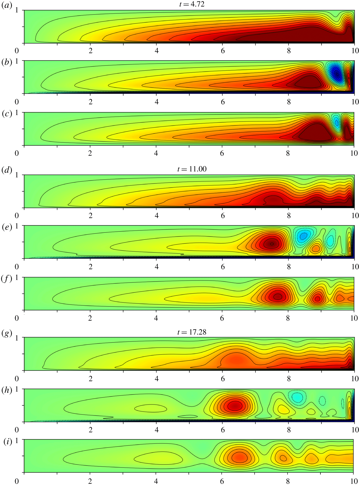
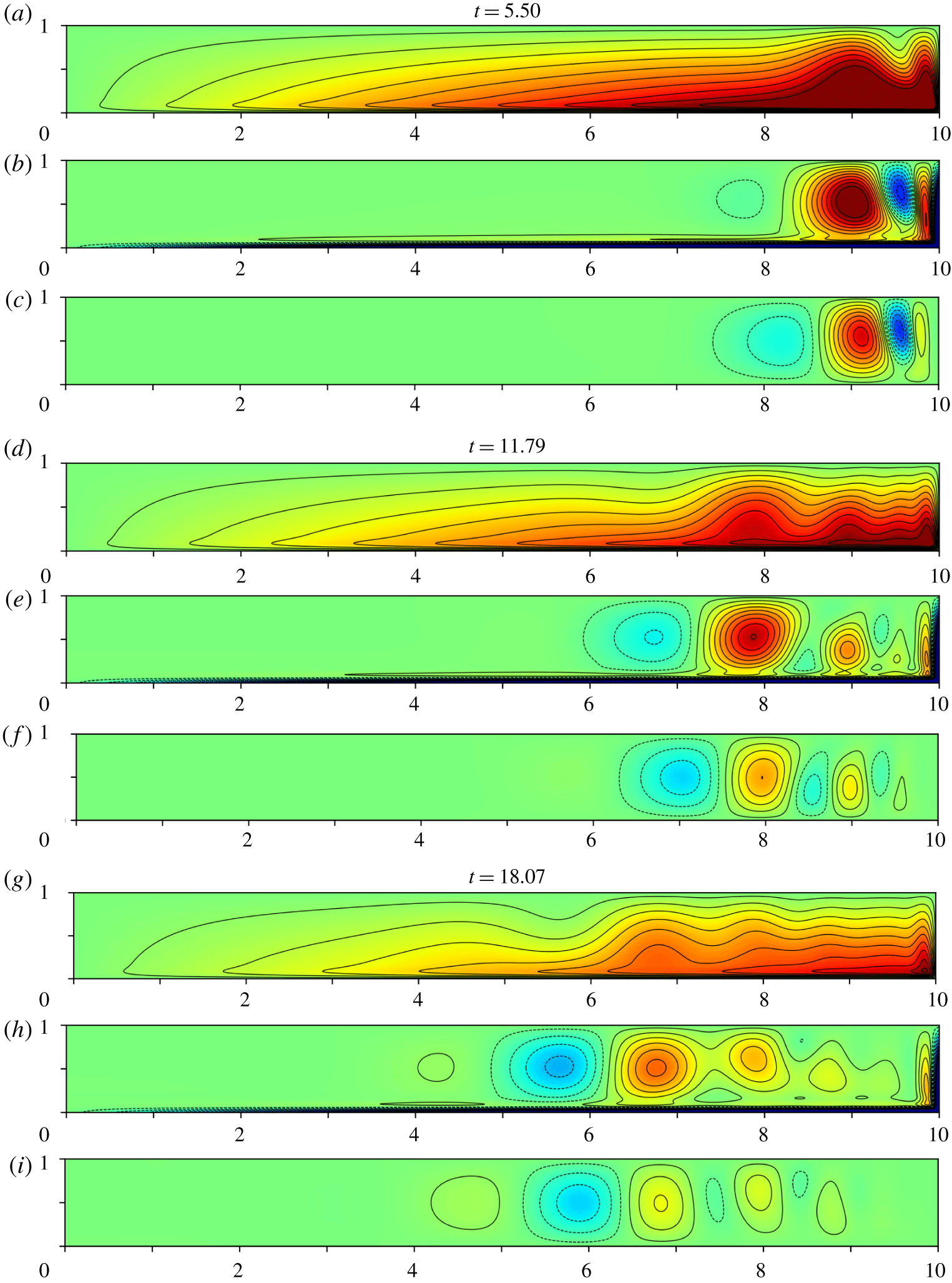
 $\unicode[STIX]{x1D712}=\text{const}.$ in figures 1, 2 (below) at various times (panels a,d,g). For that reason, we focus attention on the large
 $\ell$ case, but will comment briefly on the relative absence of wave activity for
 $\ell =1$ in our concluding § 7.
The case  $E=10^{-3}$,
 $\unicode[STIX]{x1D712}$-contours at three distinct instants
 $t=N\unicode[STIX]{x03C0}/2$ (
 $N=3,7,11$) when
 $E^{-1/2}\overline{\unicode[STIX]{x1D712}}_{MF}$ is maximised: panels (a–c), (d–f), (g–i) correspond to
 $t=4.72$,
 $11.00$,
 $17.28$, respectively. (a,d,g) Show the direct numerical simulations
 $E^{-1/2}\unicode[STIX]{x1D712}_{DNS}$ (colour scale from
 $-0.3$ to
 $0.3$); (b,e,h) and (c,f,i) show the filtered DNS, with the geostrophic flow subtracted
 $\unicode[STIX]{x1D712}_{FNS}$ and the analytic solutions
 $\unicode[STIX]{x1D712}_{IW}$, respectively (colour scale from
 $-0.1$ to
 $0.1$).

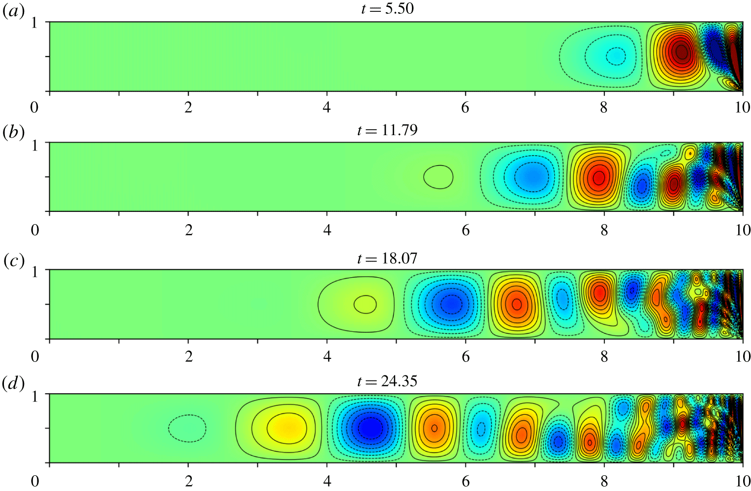
As in figure 1 but now at three distinct instants  $t=(N+{\textstyle \frac{1}{2}})\unicode[STIX]{x03C0}/2$ (
 $N=3,7,11$) at which
 $E^{-1/2}\overline{\unicode[STIX]{x1D712}}_{MF}=0$. Panels (a–c), (d–f), (g–i) correspond to
 $t=5.50$,
 $11.79$,
 $18.07$, respectively.

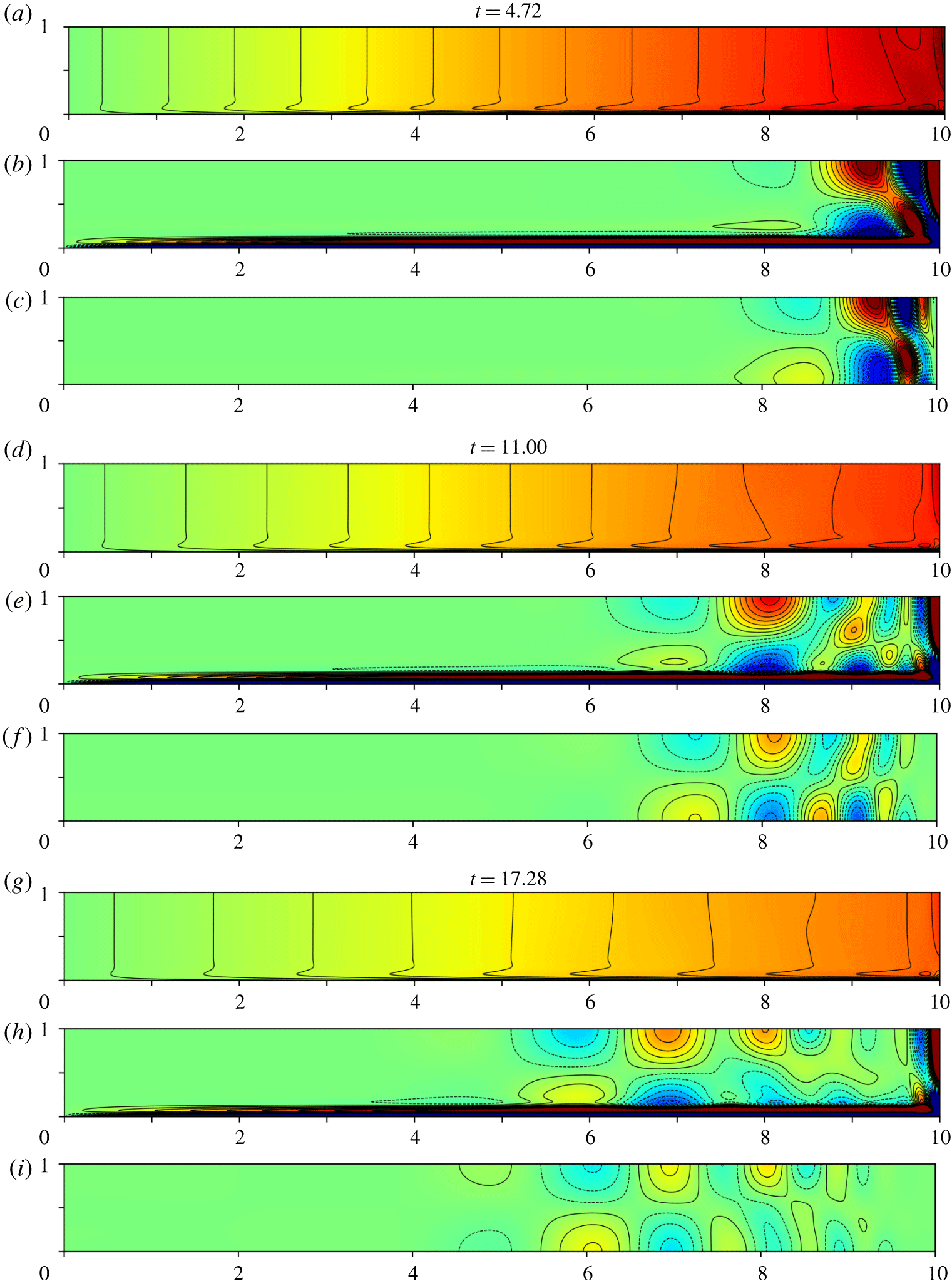
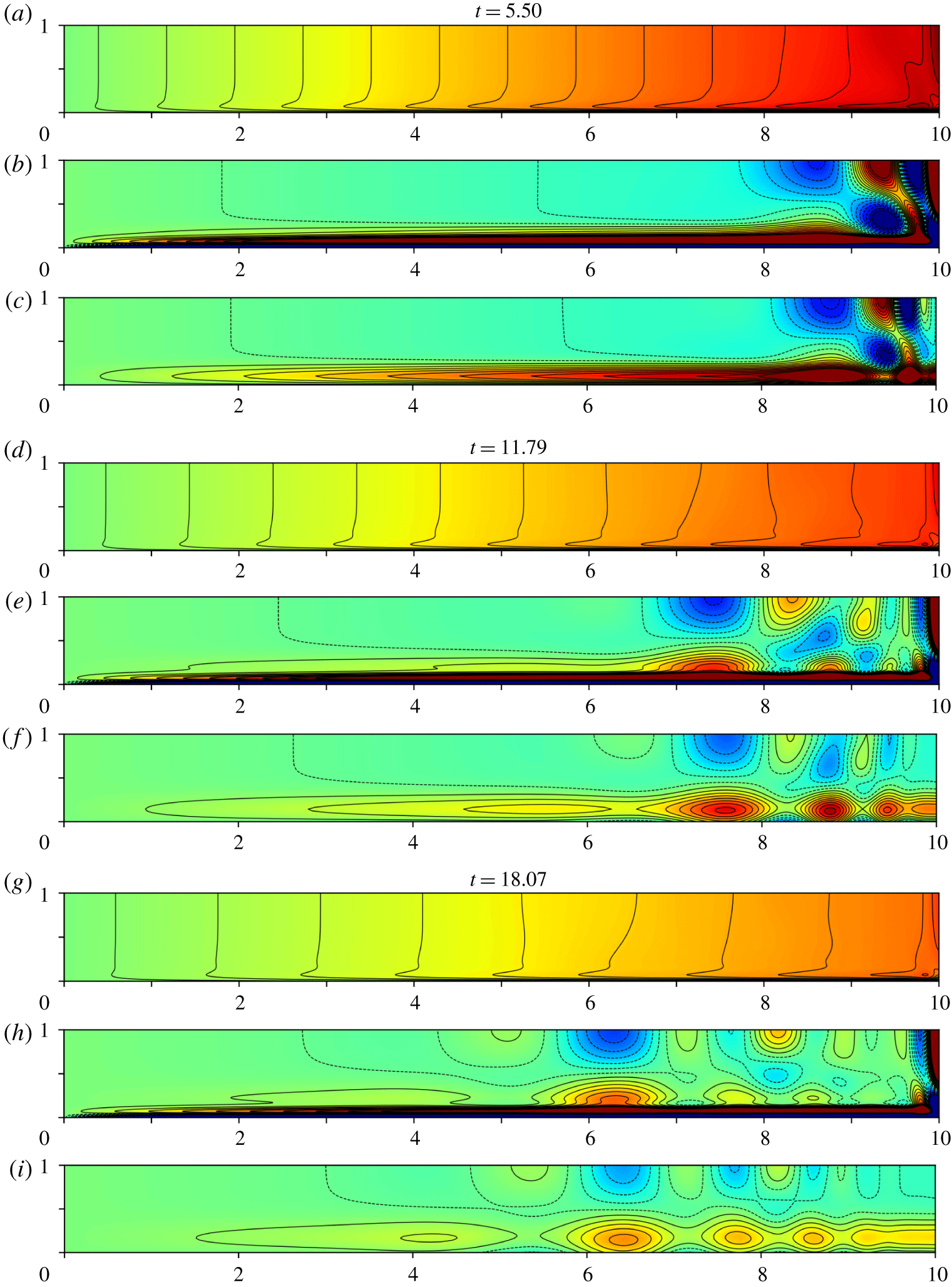
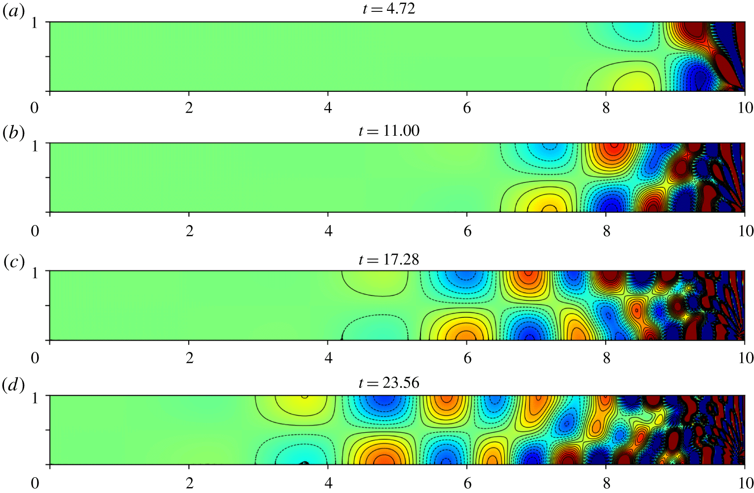
As in figure 1 but now  $v$-contours for the same instants, at which
 $E^{-1/2}\overline{v}_{MF}=0$ (equivalent to
 $E^{-1/2}\overline{\unicode[STIX]{x1D712}}_{MF}$ maximised). Panels (a,d,g) show
 $E^{-1/2}v_{DNS}$ (colour scale from
 $-30$ to
 $30$); (b,e,h) and (c,f,i) show
 $v_{FNS}$ and
 $v_{IW}$, respectively (colour scale from
 $-0.5$ to
 $0.5$).


Our asymptotic approach, based on small  $E$, builds on the premise that the Greenspan & Howard (Reference Greenspan and Howard1963) infinite plane layer solution gives a first approximation to the finite
 $\ell$ bounded problem. However, the main weakness of that solution is its serious failure to meet the impermeable boundary condition
 $u=0$ at
 $r=\ell$. Specifically, the
 $z$-independent part
 $\overline{u}(\ell ,t)$ of the radial velocity has two parts,
 $$\begin{eqnarray}\displaystyle \overline{u}_{QG}(\ell ,t)={\textstyle \frac{1}{2}}\unicode[STIX]{x1D70E}\unicode[STIX]{x1D705}E^{1/2}\mathfrak{E}(t)\quad (QG\text{-}trigger) & & \displaystyle\end{eqnarray}$$
(see (1.8)) and the remaining part
 $$\begin{eqnarray}\displaystyle \overline{u}_{MF}(\ell ,t)=\overline{u}(\ell ,t)-\overline{u}_{QG}(\ell ,t)\quad (MF\text{-}trigger). & & \displaystyle\end{eqnarray}$$
Our objective is to identify the inertial waves ‘triggered’ by demanding that the radial velocity correction is  $-\overline{u}(\ell ,t)$ at
 $r=\ell$. This simply extends the idea that flow blocking provides the trigger for the expanding QG-shear layer at
 $r=\ell$, explored in § 6 of Greenspan & Howard (Reference Greenspan and Howard1963) (see also Oruba et al. Reference Oruba, Soward and Dormy2017).
When  $t=O(1)$, the two trigger contributions
 $-\overline{u}_{QG}(\ell ,t)$ and
 $-\overline{u}_{MF}(\ell ,t)$ are of comparable size, but later, up until the spin-down time is reached,
 $1\ll t\leqslant O(E^{-1/2})$, (1.19b) gives the estimate
 $|\overline{u}_{MF}(\ell ,t)|/|\overline{u}_{QG}(\ell ,t)|=O(t^{-1/2})\ll 1$ suggesting that the QG-triggered motion dominates. Under the assumption that the MF-trigger
 $-\overline{u}_{MF}(\ell ,t)$ is of lesser importance, we ignore it and restrict our attention to the simpler QG-trigger, valid for
 $1\ll t\leqslant O(E^{-1})$. For this ‘reduced model’, we find that the triggered waves (all with frequency
 $\unicode[STIX]{x1D714}<2$) compare remarkably well with the DNS, when due account is taken of the distinct MF-wave (
 $\unicode[STIX]{x1D714}=2$) contribution (see second paragraph of § 1.3). However, the failure of our reduced model to correctly capture the early time
 $t=O(1)$ nature of the complete trigger
 $-\overline{u}(\ell ,t)$ leads to a small phase shift of the dominant wave structure at late time, just perceptible in figures 1–4. Despite this blemish, our results identify and highlight the key physical processes that operate. However, we stress that, without consideration of the complete trigger, detailed quantitative agreement is not to be expected. Finally we remark that when
 $\ell$ is relatively large, the shallow cylinder also acts as a wave guide for the triggered inertial waves.
Interestingly Cederlöf (Reference Cederlöf1988) undertook an investigation loosely related to ours in which, on p. 405, the three flow responses, items (i) QG ( $\unicode[STIX]{x1D714}=0$), (ii) MF (
 $\unicode[STIX]{x1D714}=2$), (iii) triggered inertial waves (
 $0<\unicode[STIX]{x1D714}<2$), are each identified.
1.3 Outline
On omitting the MF-flow contribution  $\overline{u}_{MF}$ responsible for the MF-trigger, we formulate in § 2 the mathematical problem for the QG-triggered wave motion,
 $E^{1/2}\boldsymbol{v}^{wave}=\boldsymbol{v}-\overline{\boldsymbol{v}}_{QG}$ (2.1), and in § 2.1 simplify using a Fourier series in
 $z$. In § 2.2 we include viscosity and solve by the Laplace transform method leading to a Fourier–Bessel series in
 $r$ (see § 2.3 and appendix A). Wave modes are damped by two mechanisms: Ekman suction (see § 2.4) and internal friction considered in § 2.3.
(i) Ekman suction leads to the decay rate
$d^{E}=O(E^{1/2}\unicode[STIX]{x1D70E}^{E})$, where the factor $\unicode[STIX]{x1D70E}^{E}=(1-|\unicode[STIX]{x1D714}|/2)^{1/2}$, estimated from (2.25b,c), depends on the frequency $\unicode[STIX]{x1D714}$. The QG-limit $\unicode[STIX]{x1D714}\rightarrow 0$ determines $d^{E}\rightarrow E^{1/2}\approx Q$ in agreement with (1.8b,d), while the MF-limit $\unicode[STIX]{x1D714}\uparrow 2$ yields $d^{E}\downarrow 0$. For that, the only damping mechanism is internal friction confined to the expanding shear layer, identified by (1.17b,d), adjacent to the lower boundary.(ii) Internal friction causes the decay rate,
$d^{\unicode[STIX]{x1D6FF}}=O(E\unicode[STIX]{x1D6FF}^{-2})$, to be dependant on the mode length scale $\unicode[STIX]{x1D6FF}$, and leads to the decay rate ratio $d^{\unicode[STIX]{x1D6FF}}/d^{E}=O(E^{1/2}/(\unicode[STIX]{x1D6FF}^{2}\unicode[STIX]{x1D70E}^{E}))$. So Ekman suction dominates when $\unicode[STIX]{x1D6FF}^{4}(1-|\unicode[STIX]{x1D714}|/2)\gg E$. However, for modes with frequency $\unicode[STIX]{x1D714}$ close to 2 or of sufficiently short length scale $\unicode[STIX]{x1D6FF}$, i.e. when $\unicode[STIX]{x1D6FF}^{4}(1-|\unicode[STIX]{x1D714}|/2)\ll E$, internal friction is more important. Such small scale structure is generated close to $r=\ell$ and quickly destroyed near that boundary at the relatively moderate value $E=10^{-3}$ used to produce the DNS-results reported in figures 1–4.











In § 3 we explain how the entire inertial wave (IW) motion  $E^{1/2}[u_{IW},v_{IW}]$, composed of the triggered inertial waves
 $E^{1/2}[u^{wave},v^{wave}]$ (see § 2) together with the basic state MF-waves
 $[u_{MF},v_{MF}]$ (including their thickening boundary layer, see (1.16) and (1.17)), may be obtained under asymptotic assumptions from the full solution by removing the QG-part (see § 3.1, particularly (3.4) and (3.6)). For
 $0<E\ll 1$, we extract from the DNS, by the same recipe, our so-called filtered-DNS, or simply FNS,
 $[u_{FNS},v_{FNS}]$ (see (3.5) and (3.7)). Our prime objective, the comparison of
 $[u_{FNS},v_{FNS}]$ with the analytic results for
 $E^{1/2}[u_{IW},v_{IW}]$ undertaken in § 3.2, is only applicable outside all quasi-steady boundary layers; they include both the Ekman layer width
 $\unicode[STIX]{x1D6E5}_{E}=E^{1/2}$ on the rigid
 $z=0$ boundary and the Stewartson sidewall layer width
 $\unicode[STIX]{x1D6E5}_{s}=E^{1/3}$ abutting the boundary
 $r=\ell$.
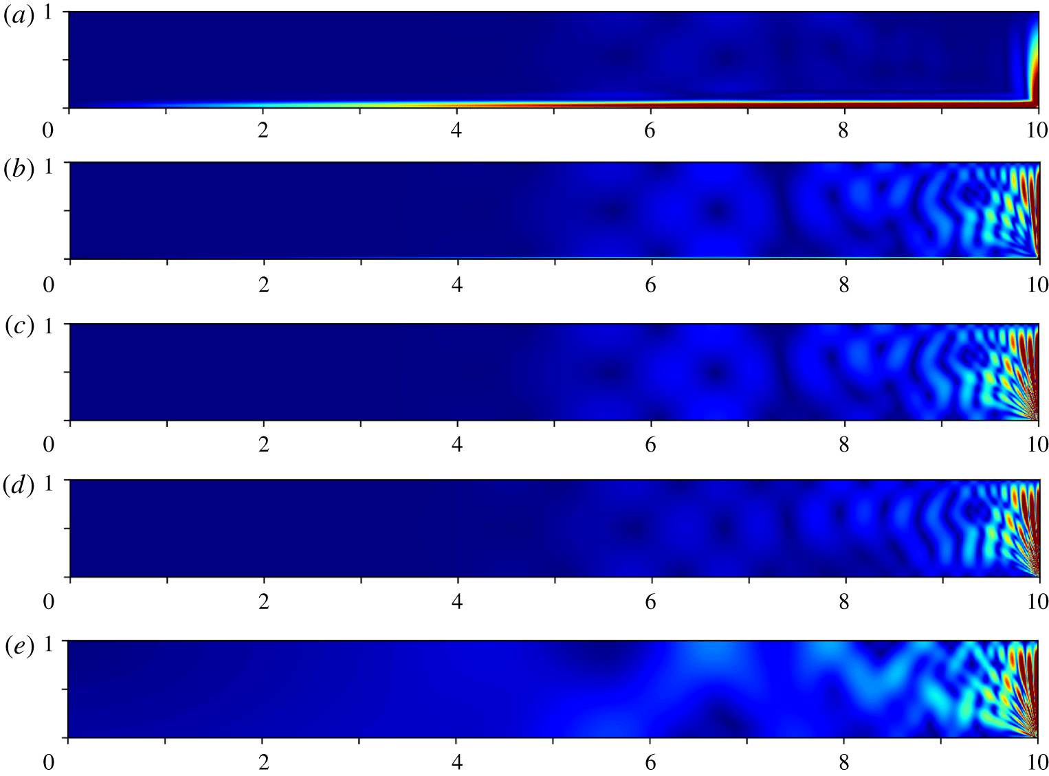
The meridional speed  $E^{-1/2}\sqrt{u^{2}+w^{2}}=r^{-1}|\unicode[STIX]{x1D735}(r\unicode[STIX]{x1D712})|$ at
 $t=18.07$ as in figure 2(g–i). Respectively, the panels show results for: (a–c) the filtered DNS
 $\unicode[STIX]{x1D712}_{FNS}$, when (a)
 $E=10^{-3}$, (b)
 $E=10^{-5}$, (c)
 $E=10^{-7}$; (d) the analytic
 $\unicode[STIX]{x1D712}^{wave}$ in the limit
 $E\downarrow 0$; (e) the full DNS
 $E^{-1/2}\unicode[STIX]{x1D712}_{DNS}$ when
 $E=10^{-7}$ (colour scale from 0 to 3).

Most of our detailed DNS/FNS/IW-comparisons are made for  $E=10^{-3}$ (see figures 1–4). They highlight the relevance of the asymptotics for moderate values of
 $E$. Smaller values of
 $E$ are used in figures 5 and 10(b). This reduces the boundary-layer widths and lessens the effect of internal friction, allowing us to see better small scale features (see also animations in supplementary material A available at https://doi.org/10.1017/jfm.2019.1064). A sharper picture of the various detailed structures identified in § 3 is obtained in § 4 upon setting
 $E=0$, which removes viscous damping entirely. To understand the complex (but elegant) wave patterns that emerge, we further restrict our domain of interest in § 4.2 to the large
 $r$-limit
 $\ell -r=O(1)$ (
 $\ell \gg 1$), for which a rectangular Cartesian approximation is applicable. Two distinct solution techniques are employed.
Firstly in § 5, due to the omission of viscosity, the simplicity of the top  $z=1$ and bottom
 $z=0$ boundaries permits our use of the method of images, convenient for handling wave reflection at
 $z=1$ and
 $0$. The primary mode (i.e. unbounded and without reflection) studied in § 5.1 (see also the supplementary material B) explains the nature of the singularity near the corner
 $[r,z]=\mathbf{0}$, while, in § 5.2 and appendix B, we appraise the full solution obtained by superimposing the images, i.e. reflections. The approach clarifies the detailed nature of the inertial waves in the vicinity of
 $r=\ell$. Further away, wave interference leaves simpler cell forms with dimensions of the gap width unity.
So, secondly, in § 6, we consider the  $(r,t)$-evolution of individual
 $m$-modes of the
 $z$-Fourier series (2.7). For given integer
 $m$, we use the method of stationary phase in § 6.2 to identify the dominant structure at given
 $(r,t)$. We find that waves reach a distance
 $x_{c}(t)=\ell -r_{c}(t)\propto m^{-1}t$ (fixed by the vanishing of the gradient of the group velocity; see (6.21e)) from the outer boundary. There the waves change character over a thickening layer width
 $\unicode[STIX]{x1D6E5}_{c}(t)\propto m^{-1}t^{1/3}$, and become evanescent (see also appendix C) for
 $\ell -r_{c}(t)>x_{c}(t)$. Since the transition is relatively abrupt, in the sense that
 $\unicode[STIX]{x1D6E5}_{c}(t)/x_{c}(t)\propto t^{-2/3}$, we refer to the layer as a front. The
 $m$-dependence,
 $x_{c}(t)\propto m^{-1}$, highlights the importance of the smallest
 $m=1$ mode and explains why detailed structure, associated with larger
 $m$, is only to be found for small
 $\ell -r$, perhaps
 $O(1)$. Significantly, since
 $\text{d}x_{c}/\text{d}t=O(1)$, the waves reach the axis after time
 $t_{axis}=O(\ell )$.
As we only report results for  $t<t_{axis}$, the relative size of
 $t_{axis}$ to the spin-down time
 $t_{sd}$, namely
 $t_{axis}/t_{sd}=O(E^{1/2}\ell )$, is pertinent. With
 $\ell =10$ and
 $E=10^{-3}$, the ratio is
 $O(1)$ but decreases in concert with
 $E$ to zero. This implies that our DNS/FNS/IW-comparisons at smaller
 $E$ pertain to earlier stages of the spin-down process. Indeed, that consideration provides the physical context, namely very early time
 $t_{axis}(\ll t_{sd})$, for our
 $E\downarrow 0$ results of §§ 4–6. We end with a few concluding remarks in § 7.
2 The mathematical problem
As already explained our objective is to investigate the inertial wave motion, velocity  $E^{1/2}\boldsymbol{v}^{wave}$, which is excited by the initial impulse caused by the failure of the radial QG-velocity
 $u=(r/\ell )\overline{\mathfrak{u}}_{QG}(t)$ (see (1.5)) to meet the boundary condition
 $u=0$ at
 $r=\ell$. This failure leads in part to a QG-correction in the form of a shear layer, width
 $\unicode[STIX]{x1D6E5}(t)=\sqrt{Et}$, expanding from
 $r=\ell$. We denote the entire QG-velocity by
 $\overline{\boldsymbol{v}}_{QG}(r,t)$, but not, of course, limited to the special rigid rotation case (1.8). Together they determine
 $$\begin{eqnarray}\displaystyle \boldsymbol{v}=\overline{\boldsymbol{v}}_{QG}+E^{1/2}\boldsymbol{v}^{wave} & & \displaystyle\end{eqnarray}$$
in the mainstream exterior to the Ekman layer adjacent to  $z=0$ and ageostrophic
 $E^{1/3}$-sidewall shear layers adjacent to
 $r=\ell$. The MF-contribution
 $\boldsymbol{v}_{MF}$ is omitted in our formulation because it is not part of the QG-trigger. Nevertheless, the MF-waves will be reinstated in order to make comparison with the DNS. For that, though the mainstream/boundary-layer decomposition (1.15)–(1.17), valid for
 $t\gg 1$, is physically illuminating, we adopt the primitive form (1.13), valid for all
 $t>0$.
Subject to the above caveats, the boundary condition  $u=0$ at
 $r=\ell$ may be expressed, using (2.1), as
 $$\begin{eqnarray}\displaystyle (\overline{u}_{QG}-\overline{\mathfrak{u}}_{QG})+E^{1/2}u^{wave}=-\overline{\mathfrak{u}}_{QG}. & & \displaystyle\end{eqnarray}$$
Elsewhere ( $0\leqslant r<\ell$), the difference
 $\overline{u}_{QG}(r,t)-(r/\ell )\overline{\mathfrak{u}}_{QG}(t)$ recovers the expanding QG-shear layer with boundary condition
 $\overline{u}_{QG}(\ell ,t)=\overline{\mathfrak{u}}_{QG}$ studied by Oruba et al. (Reference Oruba, Soward and Dormy2017). So, in what follows, we simply suppose that the inertial waves are triggered by the remaining balance
 $$\begin{eqnarray}\displaystyle u^{wave}=-E^{-1/2}\overline{\mathfrak{u}}_{QG}=-{\textstyle \frac{1}{2}}\unicode[STIX]{x1D705}\unicode[STIX]{x1D70E}\;\mathfrak{E}(t)\quad \text{at }r=\ell & & \displaystyle\end{eqnarray}$$
(see (1.8), also (1.20a), and (2.6b) below). Throughout this section we simply solve for the inertial waves  $\boldsymbol{v}^{wave}$ triggered by (2.3) and to simplify the notation drop the superscript ‘wave’ and write
 $\boldsymbol{v}=[u,v,w](\leftarrow \boldsymbol{v}^{wave})$.
The complete linear spin-up/-down problem is formulated by Greenspan & Howard (Reference Greenspan and Howard1963) in their § 2 ‘Formulation’ p. 386, where in addition the full nonlinear equation of motion is also presented. In summary, the linear equations
 $$\begin{eqnarray}\displaystyle {\displaystyle \frac{\unicode[STIX]{x2202}v}{\unicode[STIX]{x2202}t}}+2u=E(\unicode[STIX]{x1D6FB}^{2}-r^{-2})v,\quad [u,w]=\left[-{\displaystyle \frac{\unicode[STIX]{x2202}\unicode[STIX]{x1D712}}{\unicode[STIX]{x2202}z}},{\displaystyle \frac{1}{r}}{\displaystyle \frac{\unicode[STIX]{x2202}(r\unicode[STIX]{x1D712})}{\unicode[STIX]{x2202}r}}\right], & & \displaystyle\end{eqnarray}$$
 $$\begin{eqnarray}\displaystyle {\displaystyle \frac{\unicode[STIX]{x2202}\unicode[STIX]{x1D6FE}}{\unicode[STIX]{x2202}t}}-2{\displaystyle \frac{\unicode[STIX]{x2202}v}{\unicode[STIX]{x2202}z}}=E(\unicode[STIX]{x1D6FB}^{2}-r^{-2})\unicode[STIX]{x1D6FE},\quad \unicode[STIX]{x1D6FE}=-(\unicode[STIX]{x1D6FB}^{2}-r^{-2})\unicode[STIX]{x1D712} & & \displaystyle\end{eqnarray}$$
govern azimuthal momentum (2.4a) and vorticity (2.4c) (Greenspan & Howard Reference Greenspan and Howard1963 equations (2.4), (2.5) but also Oruba et al. Reference Oruba, Soward and Dormy2017 equations (2.2)–(2.4)). When restricted to our inertial wave problem, the system (2.4) is to be solved subject to the initial ( $t=0$) conditions
 $$\begin{eqnarray}\displaystyle v=0,\quad \unicode[STIX]{x1D6FE}=0, & & \displaystyle\end{eqnarray}$$
and for  $t\geqslant 0$ the boundary conditions
 $$\begin{eqnarray}\displaystyle & \displaystyle r\unicode[STIX]{x1D712}=0,\quad \text{at }r=0~(0<z\leqslant 1), & \displaystyle\end{eqnarray}$$
 $$\begin{eqnarray}\displaystyle & \displaystyle r\unicode[STIX]{x1D712}={\textstyle \frac{1}{2}}\ell \unicode[STIX]{x1D705}\unicode[STIX]{x1D70E}(z-1)\;\mathfrak{E}(t),\quad \text{at }r=\ell ~(0<z\leqslant 1), & \displaystyle\end{eqnarray}$$
 $$\begin{eqnarray}\displaystyle & \displaystyle \unicode[STIX]{x1D712}=0,\quad \text{at }z=0,1~(0<r<\ell ), & \displaystyle\end{eqnarray}$$
 $\mathfrak{E}(t)=\exp (-Qt)$ (1.8). We stress that the boundary condition (2.6b) is the essential QG-trigger of our inertial waves and the cornerstone of our investigation.
Some care is needed in the interpretation and implementation of the boundary conditions (2.6), which strictly apply to the inviscid  $E=0$ problem and are insufficient for the viscous (
 $E\not =0$) equations (2.4). From our asymptotic,
 $E\ll 1$, point of view we only address internal friction in §§ 2.1–2.3 but later incorporate the effects of Ekman boundary layers in § 2.4. Indeed, we ignore any viscous sidewall layers at
 $r=\ell$ completely, as highlighted by the discussion between (2.14) and (2.15) below. The reason for this cavalier approach is twofold:
(i) neither the quasi-steady shear layers nor the QG-evolution of spin-down associated with them have any influence on the triggered waves (see also the discussion below (2.20));
(ii) our primary concern is to identify the inertial wave generation, which is all that the
$E=0$ solution exhibits. Their damping is a secondary bookkeeping exercise needed to identify what is realised at finite $E$ so that comparisons can be made with the DNS.


2.1 The $z$-Fourier series

We seek a  $z$-Fourier series solution
 $$\begin{eqnarray}\displaystyle \left[\begin{array}{@{}c@{}}\unicode[STIX]{x1D712}\\ \unicode[STIX]{x1D6FE}\end{array}\right]=-\unicode[STIX]{x1D705}\unicode[STIX]{x1D70E}\mathop{\sum }_{m=1}^{\infty }{\displaystyle \frac{(-1)^{m}}{m\unicode[STIX]{x03C0}}}\left[\begin{array}{@{}c@{}}\widetilde{\unicode[STIX]{x1D712}}_{m}\\ \unicode[STIX]{x1D6FE}_{m}\end{array}\right]\sin (m\unicode[STIX]{x03C0}(z-1)), & & \displaystyle\end{eqnarray}$$
chosen so that  $\unicode[STIX]{x1D712}(r,z,t)$ satisfies the top and bottom boundary conditions (2.6c), and use
 $$\begin{eqnarray}\displaystyle {\textstyle \frac{1}{2}}(z-1)=-\mathop{\sum }_{m=1}^{\infty }{\displaystyle \frac{(-1)^{m}}{m\unicode[STIX]{x03C0}}}\sin (m\unicode[STIX]{x03C0}(z-1))\quad (0<z\leqslant 1) & & \displaystyle\end{eqnarray}$$
in our application of the boundary condition (2.6b). The horizontal velocity is
 $$\begin{eqnarray}\displaystyle \left[\begin{array}{@{}c@{}}u\\ v\end{array}\right]=-\unicode[STIX]{x1D705}\unicode[STIX]{x1D70E}\mathop{\sum }_{m=1}^{\infty }{\displaystyle \frac{(-1)^{m}}{m\unicode[STIX]{x03C0}}}\left[\begin{array}{@{}c@{}}\widetilde{u}_{m}\\ \widetilde{v}_{m}\end{array}\right]\cos (m\unicode[STIX]{x03C0}(z-1)). & & \displaystyle\end{eqnarray}$$
A further property of  $v$, due to its assumed form (2.7c), is
 $$\begin{eqnarray}\displaystyle \langle v\rangle =0,\quad \text{strictly }O(E^{1/2}) & & \displaystyle\end{eqnarray}$$
when the consequences of the Ekman layer are taken into account. The series (2.7a,c) satisfy (2.4) when  $\widetilde{\unicode[STIX]{x1D712}}_{m}(r,t)$ and
 $\widetilde{v}_{m}(r,t)$ are governed by
 $$\begin{eqnarray}\displaystyle {\displaystyle \frac{\unicode[STIX]{x2202}\widetilde{v}_{m}}{\unicode[STIX]{x2202}t}}+2\widetilde{u}_{m}=E\mathsf{D}_{m}\widetilde{v}_{m},\quad \widetilde{u}_{m}=-m\unicode[STIX]{x03C0}\widetilde{\unicode[STIX]{x1D712}}_{m}, & & \displaystyle\end{eqnarray}$$
 $$\begin{eqnarray}\displaystyle {\displaystyle \frac{\unicode[STIX]{x2202}\widetilde{\unicode[STIX]{x1D6FE}}_{m}}{\unicode[STIX]{x2202}t}}+2m\unicode[STIX]{x03C0}\widetilde{v}_{m}=E\mathsf{D}_{m}\widetilde{\unicode[STIX]{x1D6FE}}_{m},\quad \widetilde{\unicode[STIX]{x1D6FE}}_{m}=-\mathsf{D}_{m}\widetilde{\unicode[STIX]{x1D712}}_{m}, & & \displaystyle\end{eqnarray}$$
in which
 $$\begin{eqnarray}\displaystyle \mathsf{D}_{m}\bullet ={\displaystyle \frac{1}{r}}{\displaystyle \frac{\unicode[STIX]{x2202}}{\unicode[STIX]{x2202}r}}\left(r{\displaystyle \frac{\unicode[STIX]{x2202}\bullet }{\unicode[STIX]{x2202}r}}\right)-\left({\displaystyle \frac{1}{r^{2}}}+(m\unicode[STIX]{x03C0})^{2}\right)\bullet . & & \displaystyle\end{eqnarray}$$
They are to be solved subject to the initial ( $t=0$) conditions
 $$\begin{eqnarray}\displaystyle \widetilde{v}_{m}=0,\quad \widetilde{\unicode[STIX]{x1D6FE}}_{m}=0\quad \Longrightarrow \quad \widetilde{\unicode[STIX]{x1D712}}_{m}(r,0)=\text{I}_{1}(m\unicode[STIX]{x03C0}r)/\text{I}_{1}(m\unicode[STIX]{x03C0}\ell ) & & \displaystyle\end{eqnarray}$$
(see (2.5) together with (2.8d) and (2.10) below), and for  $t\geqslant 0$ the boundary conditions
 $$\begin{eqnarray}\displaystyle & \displaystyle r\widetilde{\unicode[STIX]{x1D712}}_{m}=0,\quad \text{at }r=0~(0<z<1), & \displaystyle\end{eqnarray}$$
 $$\begin{eqnarray}\displaystyle & \displaystyle r\widetilde{\unicode[STIX]{x1D712}}_{m}=\ell \mathfrak{E}(t),\quad \text{at }r=\ell ~(0<z<1) & \displaystyle\end{eqnarray}$$
In the following §§ 2.2 and 2.3, we solve the problem posed by (2.8)–(2.10) by the Laplace transform (henceforth LT) method. To that end it is helpful to note that the initial value,  $\widetilde{\unicode[STIX]{x1D712}}_{m}(r,0)=\text{I}_{1}(m\unicode[STIX]{x03C0}r)/\text{I}_{1}(m\unicode[STIX]{x03C0}\ell )$ (2.9c) can be represented, via the use of the Fourier–Bessel series (A 3) with
 $q=\text{i}$ (giving
 $\text{J}_{1}(\text{i}m\unicode[STIX]{x03C0}r)=\text{i}\text{I}_{1}(m\unicode[STIX]{x03C0}r)$), in the form
 $$\begin{eqnarray}\displaystyle {\displaystyle \frac{\text{I}_{1}(m\unicode[STIX]{x03C0}r)}{\text{I}_{1}(m\unicode[STIX]{x03C0}\ell )}}=-\mathop{\sum }_{n=1}^{\infty }\mathfrak{F}_{mn}{\displaystyle \frac{\text{J}_{1}(j_{n}r/\ell )}{j_{n}\text{J}_{0}(j_{n})}}\quad \text{on }0\leqslant r<\ell , & & \displaystyle\end{eqnarray}$$
where  $j_{n}$ denotes the
 $n$th zero (
 ${>}0$) of
 $\text{J}_{1}(x)$, and
 $$\begin{eqnarray}\displaystyle \mathfrak{F}_{mn}={\displaystyle \frac{q_{mn}^{2}\unicode[STIX]{x1D714}_{mn}^{2}}{2}},\quad \unicode[STIX]{x1D714}_{mn}={\displaystyle \frac{2}{\sqrt{q_{mn}^{2}+1}}},\quad q_{mn}={\displaystyle \frac{j_{n}}{m\unicode[STIX]{x03C0}\ell }}. & & \displaystyle\end{eqnarray}$$
2.2 The Laplace transform solution
We employ the LT
 $$\begin{eqnarray}\displaystyle \widehat{\bullet }(z,p)={\mathcal{L}}_{p}\{\bullet (z,t)\}\equiv \int _{0}^{\infty }\bullet (z,t)\exp (-pt)\,\text{d}t, & & \displaystyle\end{eqnarray}$$
in which the subscript ‘ $p$’ to the LT-operator
 ${\mathcal{L}}$ identifies the independent transform variable. The LT of the governing equations (2.8a–d) and initial conditions (2.9) determine
 $$\begin{eqnarray}\displaystyle & \displaystyle p\widehat{\widetilde{v}}_{m}-2m\unicode[STIX]{x03C0}\widehat{\widetilde{\unicode[STIX]{x1D712}}}_{m}=E\mathsf{D}_{m}\widehat{\widetilde{v}}_{m}, & \displaystyle\end{eqnarray}$$
 $$\begin{eqnarray}\displaystyle & \displaystyle p\mathsf{D}_{m}\widehat{\widetilde{\unicode[STIX]{x1D712}}}_{m}-2m\unicode[STIX]{x03C0}\widehat{\widetilde{v}}_{m}=E\mathsf{D}_{m}^{2}\widehat{\widetilde{\unicode[STIX]{x1D712}}}_{m}, & \displaystyle\end{eqnarray}$$
where the differential operator  $\mathsf{D}_{m}$ is defined by (2.8e),
 $$\begin{eqnarray}\displaystyle [\widehat{\widetilde{\unicode[STIX]{x1D712}}}_{m},\widehat{\widetilde{v}}_{m}](z,p)={\mathcal{L}}_{p}\{[\widetilde{\unicode[STIX]{x1D712}}_{m},\widetilde{v}_{m}]\} & & \displaystyle\end{eqnarray}$$
and  ${\mathcal{L}}_{p}$ is defined by (2.12). Elimination of
 $\widehat{\widetilde{v}}_{m}$ leads to a single equation for
 $\widehat{\widetilde{\unicode[STIX]{x1D712}}}_{m}$,
 $$\begin{eqnarray}\displaystyle (p-E\mathsf{D}_{m})^{2}\mathsf{D}_{m}\widehat{\widetilde{\unicode[STIX]{x1D712}}}_{m}-4(m\unicode[STIX]{x03C0})^{2}\widehat{\widetilde{\unicode[STIX]{x1D712}}}_{m}=0. & & \displaystyle\end{eqnarray}$$
As already stressed, we ignore viscous boundary layers and solve (2.14) on the basis that, when  $E=0$, it is second order in
 $r$, for which the endpoint boundary conditions
 $$\begin{eqnarray}\displaystyle r\widehat{\widetilde{\unicode[STIX]{x1D712}}}_{m}=0\quad \text{at }r=0\text{ and}\quad \left\{\begin{array}{@{}l@{}}r\widehat{\widetilde{\unicode[STIX]{x1D712}}}_{m}=\ell \widehat{\mathfrak{E}}(p)\quad \text{at }r=\ell ,\\ \widehat{\mathfrak{E}}(p)=(p+Q)^{-1},\end{array}\right. & & \displaystyle\end{eqnarray}$$
namely the LTs of (2.10) and (1.8d), suffice. Upon seeking modal solutions of the form
 $$\begin{eqnarray}\displaystyle \left[\begin{array}{@{}c@{}}\widehat{\widetilde{\unicode[STIX]{x1D712}}}_{m}\\ \widehat{\widetilde{v}}_{m}\end{array}\right]=\left[\begin{array}{@{}c@{}}1\\ 2m\unicode[STIX]{x03C0}/\mathfrak{p}\end{array}\right]\widehat{\mathfrak{E}}(p){\displaystyle \frac{\text{J}_{1}(m\unicode[STIX]{x03C0}qr)}{\text{J}_{1}(m\unicode[STIX]{x03C0}q\ell )}}, & & \displaystyle\end{eqnarray}$$
that meet the boundary condition (2.15b) at  $r=\ell$ and have the property
 $$\begin{eqnarray}\displaystyle \mathsf{D}_{m}\widehat{\widetilde{\unicode[STIX]{x1D712}}}_{m}=-(q^{2}+1)(m\unicode[STIX]{x03C0})^{2}\widehat{\widetilde{\unicode[STIX]{x1D712}}}_{m}, & & \displaystyle\end{eqnarray}$$
it follows from (2.14) that  $p$ and
 $q$ are related by the ‘dispersion relation’
 $$\begin{eqnarray}\displaystyle \mathfrak{p}^{2}=-4/(q^{2}+1),\quad \text{where }\mathfrak{p}=p+E(q^{2}+1)(m\unicode[STIX]{x03C0})^{2}, & & \displaystyle\end{eqnarray}$$
equivalently
 $$\begin{eqnarray}\displaystyle q^{2}+1=-4/\mathfrak{p}^{2}\quad \text{and}\quad p=\mathfrak{p}+E(2m\unicode[STIX]{x03C0})^{2}/\mathfrak{p}^{2}, & & \displaystyle\end{eqnarray}$$
from which we obtain the useful result
 $$\begin{eqnarray}\displaystyle \mathfrak{p}{\displaystyle \frac{\text{d}p}{\text{d}\mathfrak{p}}}=\mathfrak{p}-2E{\displaystyle \frac{(2m\unicode[STIX]{x03C0})^{2}}{\mathfrak{p}^{2}}}. & & \displaystyle\end{eqnarray}$$
We utilise the inverse-LT of (2.12), namely
 $$\begin{eqnarray}\displaystyle \bullet (z,t)={\mathcal{L}}_{p}^{-1}\{\widehat{\bullet }(z,p)\}\equiv {\displaystyle \frac{1}{2\unicode[STIX]{x03C0}\text{i}}}\int _{-\text{i}\infty +c}^{\text{i}\infty +c}\widehat{\bullet }(z,p)\exp (pt)\,\text{d}p, & & \displaystyle\end{eqnarray}$$
with c sufficiently large that the integration contour is to the right of all poles. When applied to  $\widehat{\widetilde{\unicode[STIX]{x1D712}}}_{m}$, defined by (2.16a), we may simply write
 $$\begin{eqnarray}\displaystyle \widetilde{\unicode[STIX]{x1D712}}_{m}={\mathcal{L}}_{p}^{-1}\left\{\widehat{\mathfrak{E}}(p){\displaystyle \frac{\text{J}_{1}(m\unicode[STIX]{x03C0}qr)}{\text{J}_{1}(m\unicode[STIX]{x03C0}q\ell )}}\right\}. & & \displaystyle\end{eqnarray}$$
The initial condition (2.9c) is recovered on expanding the corresponding integrand of the inverse-LT integral (2.18) about the limit  $p\rightarrow \infty$ (appropriate to
 $t\downarrow 0$), for which
 $q\rightarrow \text{i}$ (see (2.17a,b)) and
 $p\widehat{\mathfrak{E}}(p)\rightarrow 1$. For
 $t>0$ the inverse of (2.16a) has two parts:
 $$\begin{eqnarray}\displaystyle [\widetilde{\unicode[STIX]{x1D712}}_{m},\widetilde{v}_{m}]=[\widetilde{\unicode[STIX]{x1D712}}_{m}^{\daleth },\widetilde{v}_{m}^{\daleth }]+[\widetilde{\unicode[STIX]{x1D712}}_{m}^{AG},\widetilde{v}_{m}^{AG}]. & & \displaystyle\end{eqnarray}$$
The former inertial wave part  $[\widetilde{\unicode[STIX]{x1D712}}_{m}^{\daleth },\widetilde{v}_{m}^{\daleth }]$ stems from the residues (denoted by Res
 $\{\}$) at the set
 $\daleth$ of poles
 $p=p_{mn}(\not =0)$ linked to the zeros
 $j_{n}$ of the denominator
 $\text{J}_{1}(m\unicode[STIX]{x03C0}q\ell )$ in (2.19), i.e.
 $q=q_{mn}=j_{n}/(m\unicode[STIX]{x03C0}\ell )$ (see (2.11d)); for
 $t>0$, explicit evaluation in (2.21) below shows that each inertial wave part has the property
 $\widetilde{\unicode[STIX]{x1D712}}_{m}^{\daleth }(\ell ,t)=0$. The poles
 $p_{mn}(\not =0)$ are pure imaginary, when
 $E=0$ (see (2.17a,b)), and are thus associated with wave motion. The latter ageostrophic part
 $[\widetilde{\unicode[STIX]{x1D712}}_{m}^{AG},\widetilde{v}_{m}^{AG}]$ stems from the residues at the poles of
 $\widehat{\mathfrak{E}}(p)=(p+Q)^{-1}$ and
 $\mathfrak{p}^{-1}$. When internal friction is included (
 $d_{mn}\not =0$), this ageostrophic part determines a Stewartson
 $E^{1/3}$-layer and alone meets the boundary condition
 $\widetilde{\unicode[STIX]{x1D712}}_{m}^{AG}(\ell ,t)=\mathfrak{E}(t)$ (see (2.15b)). However, since we have not applied any stress related boundary conditions, the flow so determined is unphysical and we consider it no further. Hence, the wave part of the velocity
 $\boldsymbol{v}^{wave}$ alluded to in (2.1) is simply
 $\boldsymbol{v}^{\daleth }$, valid on the entire range
 $0\leqslant r\leqslant \ell$.
2.3 The $r$-Fourier–Bessel series

The residue calculation outlined above is messy to implement, because evaluation of the residues involves first determining the  $p$-derivatives of the denominator
 $\text{J}_{1}(m\unicode[STIX]{x03C0}q\ell )$ at the poles
 $p_{m,n}\in \daleth$. It can be done but that complication is best bypassed by use of the Fourier–Bessel series (A 3) with
 $q^{2}=-1-4/\mathfrak{p}^{2}$ (2.17a),
 $q_{mn}^{2}=-1+4/\unicode[STIX]{x1D714}_{mn}^{2}$ (see (2.11c)) giving
 $2q_{mn}^{2}/(q_{mn}^{2}-q^{2})=\mathfrak{F}_{mn}\mathfrak{p}^{2}/(\mathfrak{p}^{2}+\unicode[STIX]{x1D714}_{mn}^{2})$ on use of (2.11b). It enables us to express the residue sum for
 $[\widetilde{\unicode[STIX]{x1D712}}_{m}^{\daleth },\widetilde{v}_{m}^{\daleth }]$ derived from (2.16a) directly in the form
 $$\begin{eqnarray}\displaystyle \left[\begin{array}{@{}c@{}}\widetilde{\unicode[STIX]{x1D712}}_{m}^{\daleth }\\ \widetilde{v}_{m}^{\daleth }\end{array}\right] & = & \displaystyle -\mathop{\sum }_{n=1}^{\infty }{\displaystyle \frac{\text{J}_{1}(j_{n}r/\ell )}{j_{n}\text{J}_{0}(j_{n})}}\mathfrak{F}_{mn}\underset{p\in \daleth }{\text{Res}}\left\{\left[\begin{array}{@{}c@{}}\mathfrak{p}\\ 2m\unicode[STIX]{x03C0}\end{array}\right]{\displaystyle \frac{\mathfrak{p}\exp (pt)}{\mathfrak{p}^{2}+\unicode[STIX]{x1D714}_{mn}^{2}}}{\displaystyle \frac{1}{p+Q}}\right\}\nonumber\\ \displaystyle & = & \displaystyle -\mathop{\sum }_{n=1}^{\infty }{\displaystyle \frac{\text{J}_{1}(j_{n}r/\ell )}{j_{n}\text{J}_{0}(j_{n})}}\mathfrak{F}_{mn}\left(\underset{p\in \daleth +}{\text{Res}}\left\{\left[\begin{array}{@{}c@{}}\mathfrak{p}/2\\ m\unicode[STIX]{x03C0}\end{array}\right]{\displaystyle \frac{\exp (pt)}{\mathfrak{p}-\text{i}\unicode[STIX]{x1D714}_{mn}}}{\displaystyle \frac{1}{p+Q}}\right\}+\text{c.c.}\right).\qquad\end{eqnarray}$$
The pole structure is immediately apparent and identified by the pole half-set,  $\daleth +$,
 $$\begin{eqnarray}\displaystyle \mathfrak{p}=\mathfrak{p}_{mn}=\text{i}\unicode[STIX]{x1D714}_{mn}\quad \Longleftrightarrow \quad p=p_{mn}=\text{i}\unicode[STIX]{x1D714}_{mn}-d_{mn} & & \displaystyle\end{eqnarray}$$
having  $\unicode[STIX]{x1D714}_{mn}=\text{Im}\{\mathfrak{p}_{mn}\}>0$, which when combined with their complex conjugates (denoted by c.c.) form the complete set
 $\daleth$. On use of (2.17d,e), we determine
 $$\begin{eqnarray}\displaystyle d_{mn}={\displaystyle \frac{E(2m\unicode[STIX]{x03C0})^{2}}{\unicode[STIX]{x1D714}_{mn}^{2}}}\quad \Longrightarrow \quad \left[\mathfrak{p}{\displaystyle \frac{\text{d}p}{\text{d}\mathfrak{p}}}\right]_{\mathfrak{p}=\text{i}\unicode[STIX]{x1D714}_{mn}}=\text{i}\unicode[STIX]{x1D714}_{mn}+2d_{mn}. & & \displaystyle\end{eqnarray}$$
Evaluation of the residues in (2.21), noting that the factor  $\text{d}\mathfrak{p}/\text{d}p|_{\mathfrak{p}=\text{i}\unicode[STIX]{x1D714}_{mn}}$ is needed in the denominator, yields
 $$\begin{eqnarray}\displaystyle \left[\begin{array}{@{}c@{}}\widetilde{\unicode[STIX]{x1D712}}_{m}^{\daleth }\\ \widetilde{v}_{m}^{\daleth }\end{array}\right]=\mathop{\sum }_{n=1}^{\infty }{\displaystyle \frac{\text{J}_{1}(j_{n}r/\ell )}{j_{n}\text{J}_{0}(j_{n})}}\mathfrak{F}_{mn}\left[\begin{array}{@{}c@{}}{\unicode[STIX]{x1D712}\unicode[STIX]{x0030A}}_{mn}^{\daleth }\\ {v\unicode[STIX]{x0030A}}_{mn}^{\daleth }\end{array}\right]\exp (-\unicode[STIX]{x1D706}_{mn}t), & & \displaystyle\end{eqnarray}$$
in which  $\mathfrak{F}_{mn}$ is defined by (2.11b) and
 $$\begin{eqnarray}\displaystyle \left[\begin{array}{@{}c@{}}{\unicode[STIX]{x1D712}\unicode[STIX]{x0030A}}_{mn}^{\daleth }\\ {v\unicode[STIX]{x0030A}}_{mn}^{\daleth }\end{array}\right]=\left[\begin{array}{@{}c@{}}-{\textstyle \frac{1}{2}}\\ \text{i}m\unicode[STIX]{x03C0}/\unicode[STIX]{x1D714}_{mn}\end{array}\right]{\displaystyle \frac{\text{i}\unicode[STIX]{x1D714}_{mn}+2d_{mn}}{\text{i}\unicode[STIX]{x1D714}_{mn}-d_{mn}+Q}}\exp (\text{i}\unicode[STIX]{x1D714}_{mn}t)+\text{c.c.} & & \displaystyle\end{eqnarray}$$
Written explicitly, equation (2.23a) is
 $$\begin{eqnarray}\displaystyle & \displaystyle \widetilde{\unicode[STIX]{x1D712}}_{m}^{\daleth }=-\mathop{\sum }_{n=1}^{\infty }\mathfrak{F}_{mn}{\displaystyle \frac{\text{J}_{1}(j_{n}r/\ell )}{j_{n}\text{J}_{0}(j_{n})}}(\mathsf{C}_{mn}^{\mathfrak{E}}\cos \unicode[STIX]{x1D719}_{mn}+\mathsf{S}_{mn}^{\mathfrak{E}}\sin \unicode[STIX]{x1D719}_{mn})\exp (-\unicode[STIX]{x1D706}_{mn}t), & \displaystyle\end{eqnarray}$$
 $$\begin{eqnarray}\displaystyle & \displaystyle \widetilde{v}_{m}^{\daleth }=-\mathop{\sum }_{n=1}^{\infty }\mathfrak{F}_{mn}{\displaystyle \frac{2m\unicode[STIX]{x03C0}}{\unicode[STIX]{x1D714}_{mn}}}{\displaystyle \frac{\text{J}_{1}(j_{n}r/\ell )}{j_{n}\text{J}_{0}(j_{n})}}(\mathsf{C}_{mn}^{\mathfrak{E}}\sin \unicode[STIX]{x1D719}_{mn}-\mathsf{S}_{mn}^{\mathfrak{E}}\cos \unicode[STIX]{x1D719}_{mn})\exp (-\unicode[STIX]{x1D706}_{mn}t), & \displaystyle\end{eqnarray}$$
 $$\begin{eqnarray}\displaystyle \mathsf{C}_{mn}^{\mathfrak{E}}=1-{\displaystyle \frac{(3d_{mn}-Q)(d_{mn}-Q)}{\unicode[STIX]{x1D714}_{mn}^{2}+(d_{mn}-Q)^{2}}},\quad \mathsf{S}_{mn}^{\mathfrak{E}}={\displaystyle \frac{(3d_{mn}-Q)\unicode[STIX]{x1D714}_{mn}}{\unicode[STIX]{x1D714}_{mn}^{2}+(d_{mn}-Q)^{2}}}, & & \displaystyle\end{eqnarray}$$
and
 $$\begin{eqnarray}\displaystyle \unicode[STIX]{x1D719}_{mn}(t)=\unicode[STIX]{x1D714}_{mn}t,\quad \unicode[STIX]{x1D706}_{mn}=d_{mn}. & & \displaystyle\end{eqnarray}$$
Since the boundary condition (2.10b) on  $\widetilde{\unicode[STIX]{x1D712}}_{m}$ at
 $r=\ell$ is non-zero, it is counter-intuitive that each
 $\widetilde{\unicode[STIX]{x1D712}}_{m}^{\daleth }(\ell ,t)$ vanishes. The apparent paradox is resolved by noting the non-zero value of
 $\widetilde{\unicode[STIX]{x1D712}}_{m}(\ell ,t)$ is accommodated by the quasi-steady ageostrophic part
 $\widetilde{\unicode[STIX]{x1D712}}_{m}^{AG}(\ell ,t)$ that we disregard.
2.4 Ekman layer damping
The various frictional damping effects that we need to consider are encapsulated by equation (4.5) of Zhang & Liao (Reference Zhang and Liao2008), which consists of three sets of terms. The first corresponds to our internal friction decay rate  $d_{mn}$. The second, proportional to their
 $\unicode[STIX]{x1D6E4}^{-1}$ (our
 $\ell ^{-1}$), corresponds to decay caused by the end wall boundaries, which is negligible in our large aspect
 $\ell \gg 1$ limit. Indeed, that friction is absent for our stress-free outer boundary. The third, namely the remaining pair of terms, identifies the Ekman layer decay rate
 $d_{E}$. For that, we halve the Zhang & Liao result because we only have an Ekman layer on
 $z=0$ and no layer on
 $z=1$. Accordingly, to accommodate Ekman layer dissipation, we add the complex growth rate
 $$\begin{eqnarray}\displaystyle p_{mn}^{E\pm }=-d_{mn}^{E}\pm \text{i}\unicode[STIX]{x1D714}_{mn}^{E}, & & \displaystyle\end{eqnarray}$$
where
 $$\begin{eqnarray}\displaystyle \left[\begin{array}{@{}c@{}}d_{mn}^{E}\\ \unicode[STIX]{x1D714}_{mn}^{E}\end{array}\right]={\textstyle \frac{1}{2}}E^{1/2}\unicode[STIX]{x1D70E}_{mn+}\unicode[STIX]{x1D70E}_{mn-}\left[\begin{array}{@{}c@{}}\unicode[STIX]{x1D70E}_{mn+}^{3}+\unicode[STIX]{x1D70E}_{mn-}^{3}\\ \unicode[STIX]{x1D70E}_{mn+}^{3}-\unicode[STIX]{x1D70E}_{mn-}^{3}\end{array}\right],\quad \unicode[STIX]{x1D70E}_{mn\pm }=\sqrt{1\pm \unicode[STIX]{x1D714}_{mn}/2}\quad & & \displaystyle\end{eqnarray}$$
(c.f. also Scott Reference Scott2014, equation (2.22), but in Cartesian geometry and with time unit  $(2\unicode[STIX]{x1D6FA})^{-1}$ rather than our
 $\unicode[STIX]{x1D6FA}^{-1}$). Here, the correction
 $\unicode[STIX]{x1D714}^{E}$ to the frequency is not given by Zhang & Liao, but can be determined from the formula (2.12) of Kerswell & Barenghi (Reference Kerswell and Barenghi1995). To conclude, the formula (2.24a,b) continues to hold, but with (2.24e,f) replaced by
 $$\begin{eqnarray}\displaystyle \unicode[STIX]{x1D719}_{mn}(t)=(\unicode[STIX]{x1D714}_{mn}+\unicode[STIX]{x1D714}_{mn}^{E})t+\unicode[STIX]{x1D716}_{mn}^{E},\quad \unicode[STIX]{x1D706}_{mn}=d_{mn}+d_{mn}^{E}, & & \displaystyle\end{eqnarray}$$
in which the small phase corrections  $\unicode[STIX]{x1D716}_{mn}^{E}$ are not determined by the aforementioned results. Although
 $\unicode[STIX]{x1D716}_{mn}^{E}$ is the same size as
 $\unicode[STIX]{x1D714}_{mn}^{E}$, as time proceeds it becomes small compared to the secular phase
 $\unicode[STIX]{x1D714}_{mn}^{E}t$. Accordingly, we believe
 $\unicode[STIX]{x1D716}_{mn}^{E}$ to be unimportant and set
 $\unicode[STIX]{x1D716}_{mn}^{E}=0$ in all our numerical evaluations.
3 Comparison with the DNS
To solve the entire linear spin-down problem, we performed DNS of the full governing equations (2.4) subject to the initial conditions
 $$\begin{eqnarray}\displaystyle v/r=1,\quad r\unicode[STIX]{x1D712}=0\text{ everywhere at }t=0, & & \displaystyle\end{eqnarray}$$
and boundary conditions
 $$\begin{eqnarray}\displaystyle & \displaystyle r\unicode[STIX]{x1D712}={\displaystyle \frac{\unicode[STIX]{x2202}(v/r)}{\unicode[STIX]{x2202}r}}={\displaystyle \frac{\unicode[STIX]{x2202}w}{\unicode[STIX]{x2202}r}}=0,\quad \text{at }r=0\text{ and }\ell ~(0<z<1), & \displaystyle\end{eqnarray}$$
 $$\begin{eqnarray}\displaystyle & \displaystyle r\unicode[STIX]{x1D712}={\displaystyle \frac{\unicode[STIX]{x2202}(r\unicode[STIX]{x1D712})}{\unicode[STIX]{x2202}z}}=v/r=0,\quad \text{at }z=0~(0<r<\ell ), & \displaystyle\end{eqnarray}$$
 $$\begin{eqnarray}\displaystyle & \displaystyle r\unicode[STIX]{x1D712}={\displaystyle \frac{\unicode[STIX]{x2202}^{2}(r\unicode[STIX]{x1D712})}{\unicode[STIX]{x2202}z^{2}}}={\displaystyle \frac{\unicode[STIX]{x2202}(v/r)}{\unicode[STIX]{x2202}z}}=0,\quad \text{at }z=1~(0<r<\ell ), & \displaystyle\end{eqnarray}$$
We solved (2.4) using second-order finite differences in space, and an implicit second-order backward differentiation (BDF2) in time. We used a stretched grid, staggered in the  $z$-direction. The simulations were performed with a spatial resolution up to
 $2500\times 2000$, a convergence study confirmed that this resolution is sufficient at the Ekman number considered here.
In § 2 we considered, from an asymptotic point of view, the inertial wave response  $E^{1/2}\boldsymbol{v}^{wave}$ outside the Ekman layer (see (2.1)) to the QG-trigger subject to the reduced set of initial and boundary conditions (2.5) and (2.6). The superscript ‘wave’, dropped in § 2, is reinstated throughout this section. On excluding the sidewall layers, we have
 $E^{1/2}\boldsymbol{v}^{wave}=E^{1/2}\boldsymbol{v}^{\daleth }$, i.e. the pole contributions. Those considerations ignored the MF-wave contribution
 $\boldsymbol{v}_{MF}$, which needs to be added to
 $E^{1/2}\boldsymbol{v}^{wave}$ to construct the complete inertial wave structure
 $E^{1/2}\boldsymbol{v}_{IW}$,
 $$\begin{eqnarray}\displaystyle \boldsymbol{v}=\overline{\boldsymbol{v}}_{QG}+E^{1/2}\boldsymbol{v}_{IW},\quad E^{1/2}\boldsymbol{v}_{IW}=\boldsymbol{v}_{MF}+E^{1/2}\boldsymbol{v}^{wave}. & & \displaystyle\end{eqnarray}$$
Our goal is to compare the § 2 results with the DNS identified by the subscript ‘ $DNS$’ and illustrated in panels (a,d,g) of figures 1–4 (below). Care must be taken with the scale factor
 $E^{1/2}$ introduced in
 $E^{1/2}\boldsymbol{v}_{IW}$,
 $E^{1/2}\boldsymbol{v}^{wave}$ and evident in the relations (3.4)–(3.7) (below). Once these inter-relations have been set up in the following § 3.1, we adopt the scaling
 $E^{-1/2}\boldsymbol{v}$ (as in
 $\boldsymbol{v}_{IW}$,
 $\boldsymbol{v}^{wave}$) for our reference velocity unit in all our figures.
3.1 The filtered DNS-velocity $\boldsymbol{v}_{FNS}$

The most dominant feature of the spin-down, exterior to the bottom Ekman layer, is the  $z$-independent azimuthal QG-flow
 $\overline{v}_{QG}$, which is larger by a factor of at least
 $O(E^{-1/2})$ than almost all other contributions to the complete flow description. So, to make comparison with results based on our § 2 theory for
 $E^{1/2}v^{wave}$, we need to remove
 $\overline{v}_{QG}$ from
 $v$. As
 $\overline{v}_{QG}$ is not easily identifiable from the numerics, we determine it indirectly from the
 $z$-average
 $\langle v\rangle$ of
 $v$. To this end, we note that, on ignoring all wave motion, equation (1.11) indicates that
 $\langle v\rangle =\unicode[STIX]{x1D707}\overline{v}_{QG}+O(E)$, a result that even holds in the expanding QG-shear layer adjacent to the outer boundary
 $r=\ell$. Interestingly, for
 $t\gg 1$, although the MF-wave has
 $\overline{v}_{MF}=O((E/t)^{1/2})$ (see (1.17c), its
 $z$–average
 $\langle \overline{v}_{MF}\rangle$ is smaller by a factor
 $O(t^{-1})$:
 $\langle v_{MF}\rangle =O(E^{1/2}t^{-3/2})$ (see (1.18)). Furthermore the inertial waves
 $E^{1/2}v^{wave}$ in their assumed form (2.7c) have zero
 $z$-average. That assumption is based on neglect of their associated Ekman layer. In practice, these Ekman layers carry an azimuthal flux smaller by a factor
 $O(E^{1/2})$ so that
 $E^{1/2}\langle v^{wave}\rangle =O(E)$. This fortuitous estimate indicates that the (IW-)contribution
 $E^{1/2}v_{IW}$ (3.3b), outside the Ekman layer, is related to the full solution by
 $$\begin{eqnarray}\displaystyle v_{IW}=E^{-1/2}v_{MF}+v^{wave}=E^{-1/2}(v-\unicode[STIX]{x1D707}^{-1}\langle v\rangle )+O(E^{1/2}) & & \displaystyle\end{eqnarray}$$
on a spin-down time  $t=O(E^{-1/2})$ large compared to unity.
We also assume that the quasi-steady  $z$-dependent correction to
 $\overline{v}_{QG}$ is relatively small
 $O(E|\overline{v}_{QG}|)$ (see Oruba et al. Reference Oruba, Soward and Dormy2017, equation (2.11a)) so that its presence on the right-hand side of (3.4) does not corrupt the recipe for the IW-part
 $v_{IW}$, at any rate to the order of accuracy needed. Importantly, we may evaluate
 $v-\unicode[STIX]{x1D707}^{-1}\langle v\rangle$ directly from the DNS results and refer to
 $$\begin{eqnarray}\displaystyle v_{FNS}=E^{-1/2}(v_{DNS}-\unicode[STIX]{x1D707}^{-1}\langle v_{DNS}\rangle ) & & \displaystyle\end{eqnarray}$$
as the ‘filtered DNS’ or simply FNS. It should be emphasised that this filter is delicate as it needs to determine the difference of the  $O(1)$ quantities
 $v_{DNS}$ and
 $\unicode[STIX]{x1D707}^{-1}\langle v_{DNS}\rangle$ accurately to
 $O(E^{1/2})$. In figures 3 and 4 (below), we portray
 $v_{FNS}$ in the FNS panels (b,e,h), derived from
 $E^{-1/2}v_{DNS}$ illustrated in the DNS panels (a,d,g), while
 $v_{IW}$ is shown in the IW panels (c,f,i).
All contributions to the radial flow  $u$ are
 $O(E^{1/2})$. Nevertheless, just as for
 $v$, we need to first identify the QG-part
 $\overline{u}_{QG}={\textstyle \frac{1}{2}}\unicode[STIX]{x1D70E}E^{1/2}\overline{v}_{QG}={\textstyle \frac{1}{2}}(\unicode[STIX]{x1D70E}/\unicode[STIX]{x1D707})E^{1/2}\langle v_{QG}\rangle$ (the same recipe as in (1.8a,b), also (1.11)), and note that the IW-contribution, outside the Ekman layer, is
 $$\begin{eqnarray}\displaystyle u_{IW}=E^{-1/2}u_{MF}+u^{wave} & = & \displaystyle E^{-1/2}(u-\overline{u}_{QG})+O(E^{1/2})\nonumber\\ \displaystyle & = & \displaystyle E^{-1/2}u-{\textstyle \frac{1}{2}}(\unicode[STIX]{x1D70E}/\unicode[STIX]{x1D707})\langle v\rangle +O(E^{1/2})\end{eqnarray}$$
on the spin-down time  $t=O(E^{-1/2})$. Exactly as before in our consideration of
 $\overline{v}_{QG}$, we neglect the small quasi-steady
 $z$-dependent correction
 $O(E|\overline{u}_{QG}|)$ to
 $\overline{u}_{QG}$ (see Oruba et al. Reference Oruba, Soward and Dormy2017, equation (2.11b)) on the right-hand side of (3.6a). On defining the mainstream streamfunction as
 $r\unicode[STIX]{x1D712}=r\int _{z}^{1}u\,\text{d}z$, we may extract the IW-part via the recipe
 $$\begin{eqnarray}\displaystyle \unicode[STIX]{x1D712}_{IW}=E^{-1/2}\unicode[STIX]{x1D712}_{MF}+\unicode[STIX]{x1D712}^{wave}=E^{-1/2}\unicode[STIX]{x1D712}-{\textstyle \frac{1}{2}}(\unicode[STIX]{x1D70E}/\unicode[STIX]{x1D707})(1-z)\langle v\rangle +O(E^{1/2}). & & \displaystyle\end{eqnarray}$$
The results (3.6a,b) suggest that we define the radial FNS-velocity and streamfunction by
 $$\begin{eqnarray}\displaystyle & \displaystyle u_{FNS}=E^{-1/2}u_{DNS}-{\textstyle \frac{1}{2}}(\unicode[STIX]{x1D70E}/\unicode[STIX]{x1D707})\langle v_{DNS}\rangle , & \displaystyle\end{eqnarray}$$
 $$\begin{eqnarray}\displaystyle & \displaystyle \unicode[STIX]{x1D712}_{FNS}=E^{-1/2}\unicode[STIX]{x1D712}_{DNS}-{\textstyle \frac{1}{2}}(\unicode[STIX]{x1D70E}/\unicode[STIX]{x1D707})(1-z)\langle v_{DNS}\rangle . & \displaystyle\end{eqnarray}$$
 $E^{-1/2}\unicode[STIX]{x1D712}_{DNS}$ in the DNS panels (a,d,g),
 $\unicode[STIX]{x1D712}_{FNS}$ in the FNS panels (b,e,h) and
 $\unicode[STIX]{x1D712}_{IW}$ in the IW panels (c,f,i).
3.2 The inertial wave $\boldsymbol{v}_{IW}$ comparison with $\boldsymbol{v}_{FNS}$


In the FNS and IW panels of figures 1–4, contours are scaled consistently as in (3.4)–(3.7) so that amplitude comparisons are readily discernible. The full DNS results, however, exhibit a wider amplitude range, because they contain, in addition to the IW-contribution, the generally large QG-part. It is therefore impractical to employ the same scaling in the DNS panels as used in the FNS and IW panels. The DNS panels are, however, important as they illustrate the entire spin-down process and provide a visual measure of the relevance of the IW-contribution. This is particularly pertinent to  $E^{-1/2}v_{DNS}$ which is
 $O(E^{-1/2})$ larger than both
 $v_{FNS}$ and
 $v_{IW}$.
The results portrayed in figures 1–4 all concern  $E=10^{-3}$. The lower Ekman layer has width
 $E^{1/2}\doteqdot 0.03$, which is perhaps most readily identifiable in the azimuthal velocity
 $E^{-1/2}v$ contour plots of figures 3 and 4. The well-known Ekman spiral is evident in the DNS panels, whereas on the blown up scale of the FNS panels it blurs and appears as thin black shaded layer. There is also a persistent ageostrophic
 $E^{1/3}$-sidewall layer at
 $r=\ell$ of width
 $0.1$. Our FNS- and IW-results are only meaningful in the regions exterior to those quasi-static boundary layers. Note that neither the Ekman layer nor the sidewall layer appears on the IW panels as they are not part of either of the constituents (
 $\unicode[STIX]{x1D712}_{MF}$,
 $v_{MF}$) or (
 $\unicode[STIX]{x1D712}^{wave}$,
 $v^{wave}$) that together compose the IW-solution.
The time range of our plots starts at  $t=4.72>1$ (i.e. large compared to the spin-down time) in figures 1 and 3, panels (a–c) and ends at
 $t=18.07<10^{3}$ (i.e. short compared to the MF boundary-layer (width
 $\unicode[STIX]{x1D6E5}(t)=\sqrt{Et}$ (1.4b)) diffusion time
 $E^{-1}$ needed to fill
 $0<z<1$) in figures 2 and 4, panels (g–i). Essentially, the results apply on the spin-down time
 $t_{sd}=E^{-1/2}\doteqdot 30$. The actual times chosen in figure 1 (3) are
 $t=N\unicode[STIX]{x03C0}/2$ (
 $N=3,7,11$) at which the MF-wave contribution
 $E^{-1/2}\overline{\unicode[STIX]{x1D712}}_{MF}\propto \cos (2t)$ given by (1.17a) is maximised (for
 $E^{-1/2}\overline{v}_{MF}\propto \sin (2t)=0$, see (1.17c)). The times
 $t=(N+{\textstyle \frac{1}{2}})\unicode[STIX]{x03C0}/2$ (
 $N=3,7,11$) used in figure 2 (4) are when
 $E^{-1/2}\overline{\unicode[STIX]{x1D712}}_{MF}\propto \cos (2t)=0$ (
 $E^{-1/2}\overline{v}_{MF}\propto \sin (2t)$ is maximised). The idea is that at times when
 $E^{-1/2}\overline{\unicode[STIX]{x1D712}}_{MF}=0$ (
 $E^{-1/2}\overline{v}_{MF}=0$), the FNS and IW panels for
 $E^{-1/2}\unicode[STIX]{x1D712}$ (
 $E^{-1/2}v$) in figure 2 (3) simply describe
 $\unicode[STIX]{x1D712}^{wave}$ (
 $v^{wave}$). However, at times, when
 $E^{-1/2}\overline{\unicode[STIX]{x1D712}}_{MF}$ (
 $E^{-1/2}\overline{v}_{MF}$) are maximised, the FNS and IW panels for
 $E^{-1/2}\unicode[STIX]{x1D712}$ (
 $E^{-1/2}v$) in figure 1 (4), through comparison with figure 2 (3), identify the role of the
 $E^{-1/2}\overline{\unicode[STIX]{x1D712}}_{MF}$ (
 $E^{-1/2}\overline{v}_{MF}$) contribution. Perhaps the most striking characteristic of this comparison is that
 $E^{-1/2}\overline{\unicode[STIX]{x1D712}}_{MF}$ (
 $E^{-1/2}\overline{v}_{MF}$) identified in figure 1 (4) is non-zero throughout the entire domain, just as predicted by (1.17a (c)). By contrast
 $\unicode[STIX]{x1D712}^{wave}$ (
 $v^{wave}$) identified in figure 2 (3) is only non-zero for a limited radial extent from the outer boundary
 $r=\ell$. In the following § 4 we ignore all damping and in § 6 explain this phenomenon. There is also much detailed structure in a subdomain close to
 $r=\ell$, which we explain in § 5.
As explained in § 1.1.2(b) and noted earlier in this subsection in the context of time scales, the MF-wave possesses a spreading boundary-layer width  $\unicode[STIX]{x1D6E5}(t)=\sqrt{Et}$ adjacent to the lower boundary
 $z=0$ quantified by (1.17b,d). This layer is most clearly evident in the IW panels of figure 4 (sufficiently far to the left for
 $v^{wave}$ to be negligible), for which the Ekman layer is absent. It is also evident in the FNS panels, where it extends beyond the prominent Ekman layer. These features can also be identified, but less obviously, in the corresponding panels of figure 1 (sufficiently far to the left for
 $u^{wave}$ to be negligible).
The values of  $\unicode[STIX]{x1D712}^{wave}$,
 $v^{wave}$ used for our IW-plots are given by the
 $z$-Fourier series (2.7a,c) using
 $\widetilde{\unicode[STIX]{x1D712}}_{m}$,
 $\widetilde{v}_{m}$ determined by (2.24a,b). Since we found that the slow decay of the QG-flow has virtually no effect on the result, we set
 $$\begin{eqnarray}\displaystyle Q=E^{1/2}\unicode[STIX]{x1D70E}=0 & & \displaystyle\end{eqnarray}$$
in (2.24c,d), which define the parameters  $\mathsf{C}_{mn}^{\mathfrak{E}}$,
 $\mathsf{S}_{mn}^{\mathfrak{E}}$ (2.24a,b). As the formulae (2.24c,d) for the phase
 $\unicode[STIX]{x1D719}_{mn}(t)$ and decay rate
 $\unicode[STIX]{x1D706}_{mn}$ account only for the damping by internal friction, we used instead (2.26a,b), which also takes into account Ekman damping, but with the slight change of phase
 $\unicode[STIX]{x1D716}_{mn}^{E}$ set to zero, as explained there. To assess whether or not our damping predictions are reasonable, we need to compare the FNS IW panels for
 $\unicode[STIX]{x1D712}_{FNS}$ and
 $\unicode[STIX]{x1D712}_{IW}$ in figure 2 (noting that
 $E^{-1/2}\overline{\unicode[STIX]{x1D712}}_{MF}\approx 0$) and
 $v_{FNS}$ and
 $v_{IW}$ in figure 3 (noting that
 $E^{-1/2}\overline{v}_{MF}\approx 0$). Our theoretical model, although generally good, appears to slightly overestimate damping on the shorter length scales. This appears to be a shortcoming of our choice of the QG-trigger
 $\overline{u}_{QG}(\ell ,t)={\textstyle \frac{1}{2}}\unicode[STIX]{x1D70E}\unicode[STIX]{x1D705}E^{1/2}\mathfrak{E}(t)$ (1.20a). As we will report elsewhere, the inclusion of the MF-trigger
 $\overline{u}_{MF}(\ell ,t)$ improves the comparison.
4 No damping $E\downarrow 0$

With dissipation included the  $z$-Fourier series representations (2.7a,c) for
 $\unicode[STIX]{x1D712}$ and
 $v$ (the superscript ‘wave’ is again generally dropped, except to avoid ambiguity when discussing numerical results portrayed in the figures), possessing
 $r$-Fourier-Bessel series coefficients (2.24a,b) with parameter values (2.24c,d) and (2.26a,b), determine results, which compare well with the DNS for
 $E=10^{-3}$, as figures 1–4 in § 3 illustrate. Nevertheless, at that moderately small
 $E$, motion on small scales suffers considerable dissipation and decays rapidly.
To assess the extent to which our wave predictions are visible at smaller  $E$, we plot filtered DNS (FNS) contours of the meridional speed
 $E^{-1/2}\sqrt{u^{2}+w^{2}}=r^{-1}|\unicode[STIX]{x1D735}(r\unicode[STIX]{x1D712})|$ at
 $E=10^{-3}$,
 $10^{-5}$ and
 $10^{-7}$ in figure 5(a–c) at
 $t=18.07$. As
 $E$ decreases from
 $10^{-3}$, a fan structure emerges near the corner
 $[r,z]=[\ell ,0]$, which converges rapidly to that for the analytic
 $\unicode[STIX]{x1D712}^{wave}$ contours at
 $E=0$ portrayed in figure 5(d). Although
 $\unicode[STIX]{x1D712}_{IW}=E^{-1/2}\unicode[STIX]{x1D712}_{MF}+\unicode[STIX]{x1D712}^{wave}$ (see (3.6b)), rather than
 $\unicode[STIX]{x1D712}^{wave}$, ought to be compared with the FNS results, the good agreement of figure 5(c,d) suggests that the MF-contribution is negligible, a suggestion supported by inspection of figure 10(b) at the ordinate
 $t=18.07$ (see also the discussion in the penultimate paragraph of § 6.3 prior to § 7). Finally we plot unfiltered DNS contours at
 $E=10^{-7}$ in figure 5(e) expecting the QG-contribution to
 $\unicode[STIX]{x1D712}_{DNS}$ to obscure the waves. That does not happen; instead, the wave pattern remains prominent though somewhat distorted by the QG-flow.
To explore the suggestions from the small  $E$ results of figure 5 in more detail, we formulate the
 $E\downarrow 0$ problem in § 4.1 and then identify a large
 $r$ domain in § 4.2 amenable to asymptotic study.
4.1 Formulation and results
On setting  $E=0$ in (2.4a–d), these governing equations together with the initial conditions (2.5a,b) and boundary condition
 $\unicode[STIX]{x1D712}=0$ at
 $z=1$ (2.6c) determine
 $$\begin{eqnarray}\displaystyle \unicode[STIX]{x1D712}=\int _{z}^{1}u\,\text{d}z,\quad v=-2\int _{0}^{t}u\,\text{d}t=2\int _{0}^{t}{\displaystyle \frac{\unicode[STIX]{x2202}\unicode[STIX]{x1D712}}{\unicode[STIX]{x2202}z}}\,\text{d}t,\quad \unicode[STIX]{x1D6FE}=2\int _{0}^{t}{\displaystyle \frac{\unicode[STIX]{x2202}v}{\unicode[STIX]{x2202}z}}\,\text{d}t. & & \displaystyle\end{eqnarray}$$
We continue to consider the representations (2.7a,c) and (2.24a,b), in which  $\mathfrak{F}_{mn}=q_{mn}^{2}\unicode[STIX]{x1D714}_{mn}^{2}/2$ (2.11b) and
 $\unicode[STIX]{x1D719}_{mn}=\unicode[STIX]{x1D714}_{mn}t$ (2.24e), but set
 $E^{1/2}\unicode[STIX]{x1D70E}=Q=0$,
 $\unicode[STIX]{x1D705}=\unicode[STIX]{x1D70E}=1$,
 $d_{mn}=0$ so that the coefficients become
 $\mathsf{C}_{mn}^{\mathfrak{E}}=1$,
 $\mathsf{S}_{mn}^{\mathfrak{E}}=0$ (see (2.24c,d)) and
 $\unicode[STIX]{x1D706}_{mn}=0$ (see (2.24f)). In this way, equation (2.24a,b) yield
 $$\begin{eqnarray}\displaystyle & \displaystyle \widetilde{\unicode[STIX]{x1D712}}_{m}=\widetilde{\unicode[STIX]{x1D712}}_{m}^{\daleth }=-\mathop{\sum }_{n=1}^{\infty }{\displaystyle \frac{q_{mn}^{2}\unicode[STIX]{x1D714}_{mn}^{2}}{2}}{\displaystyle \frac{\text{J}_{1}(j_{n}r/\ell )}{j_{n}\text{J}_{0}(j_{n})}}\cos (\unicode[STIX]{x1D714}_{mn}t), & \displaystyle\end{eqnarray}$$
 $$\begin{eqnarray}\displaystyle & \displaystyle \left[\begin{array}{@{}c@{}}\widetilde{u}_{m}\\ \widetilde{v}_{m}\end{array}\right]=\left[\begin{array}{@{}c@{}}\widetilde{u}_{m}^{\daleth }\\ \widetilde{v}_{m}^{\daleth }\end{array}\right]=\mathop{\sum }_{n=1}^{\infty }{\displaystyle \frac{q_{mn}\unicode[STIX]{x1D714}_{mn}^{2}}{2}}{\displaystyle \frac{\text{J}_{1}(j_{n}r/\ell )}{\ell \text{J}_{0}(j_{n})}}\left[\begin{array}{@{}c@{}}\cos (\unicode[STIX]{x1D714}_{mn}t)\\ -(2/\unicode[STIX]{x1D714}_{mn})\sin (\unicode[STIX]{x1D714}_{mn}t)\end{array}\right]. & \displaystyle\end{eqnarray}$$
4.1.1 The $E\downarrow 0$ results

Some solutions  $\unicode[STIX]{x1D712}^{wave}=\unicode[STIX]{x1D712}$ and
 $v^{wave}=v$, realised by substitution of (4.2) into (2.7a,c), are illustrated in figures 6 and 7, respectively. The times
 $t=5.50$, 11.79, 18.07 adopted in the first three panels (a–c) of figure 6 correspond to the prescription
 $t=(N+{\textstyle \frac{1}{2}})\unicode[STIX]{x03C0}/2$ (
 $N=3,7,11$) adopted in figure 2, for which
 $E^{-1/2}\overline{\unicode[STIX]{x1D712}}_{MF}=0$. By this choice, we see how the small scale structure of
 $\unicode[STIX]{x1D712}^{wave}$ visible in figure 6(a–c) particularly near the outer boundary
 $r=\ell$ is largely eliminated by dissipation in the contour plots of
 $\unicode[STIX]{x1D712}_{IW}$ in figure 2(c,f,i). Likewise, at times
 $t=4.72$, 11.00, 17.28, i.e.
 $t=N\unicode[STIX]{x03C0}/2$ (
 $N=3,7,11$) when
 $E^{-1/2}\overline{v}_{MF}=0$, a similar comparison of figure 7(a–c) with figure 3(c,f,i) can be made. To understand in detail this small scale structure, we formulate an asymptotic approach in § 4.2 based on
 $\ell \gg 1$ (see (4.5)), which we apply in §§ 5 and 6.
The analytic  $\unicode[STIX]{x1D712}^{wave}$-contours in the
 $E\downarrow 0$ limit at sequential times
 $t=(N+{\textstyle \frac{1}{2}})\unicode[STIX]{x03C0}/2$. (a)
 $N=3$, (b)
 $N=7$, (c)
 $N=11$, cf. figures 2(c), (f), (i) respectively. (d)
 $N=15$ (colour scale from
 $-0.1$ to 0.1).

The analytic  $v^{wave}$-contours in the
 $E\downarrow 0$ limit at sequential times
 $t=N\unicode[STIX]{x03C0}/2$. (a)
 $N=3$, (b)
 $N=7$, (c)
 $N=11$, cf. figures 3(c), (f), (i), respectively. (d)
 $N=15$ (colour scale from
 $-0.5$ to 0.5).

A striking feature of  $\unicode[STIX]{x1D712}^{wave}$ plotted in figure 6, but also evinced by the
 $v^{wave}$ plots in figure 7, is the limited distance,
 $x(t)=\ell -r(t)$ (say), reached by the wave disturbance triggered at the outer boundary
 $r=\ell$. For that reason, it is instructive to consider results for the individual Fourier modes
 $$\begin{eqnarray}\displaystyle \unicode[STIX]{x1D712}_{m}^{wave}(r,z,t)=-(m\unicode[STIX]{x03C0})^{-1}\widetilde{\unicode[STIX]{x1D712}}_{m}\sin (m\unicode[STIX]{x03C0}z) & & \displaystyle\end{eqnarray}$$
(see (2.7a)) for which contour plots with  $m=1,2$ are illustrated in figure 8 at times
 $t=15$ and
 $25$. Indeed, on comparing the
 $m=1$ panels (a,b) with the
 $m=2$ panels (c,d), suggests that each of these two
 $m$-modes reaches a distance
 $x_{m}(t)=\ell -r_{m}(t)$ related by
 $x_{1}(t)\approx 2x_{2}(t)$, with the possible implication that the larger
 $m$-modes reach a distance decreasing with
 $m$. This idea is explored further in the space–time (
 $0<t\leqslant 30$) contour plots of
 $\unicode[STIX]{x1D712}_{m}^{wave}(r,z_{m},t)$, for the
 $m=1,2$ modes, in figure 9(a,b), at their respective maxima
 $z_{1}=0.5$,
 $z_{2}=0.25$. From these the spatial extent
 $r_{m}(t)\lesssim r<\ell$ is clearly visible.
In view of the above remarks, we reassess the wave activity in figures 6 and 7. Sufficiently far to the left, the waves, when existent, are clearly dominated by the  $m=1$ mode. On halving the distance to the right-hand outer boundary,
 $r=\ell$, some interference from the
 $m=2$ mode is visible. Yet further reduction of that distance leads to interference from successive higher harmonics, that complicates the picture more. Note too that, though the waves penetrate further to the left with time, a feature of their negative group velocity, the waves themselves propagate to the right with positive phase velocity.
The analytic  $\unicode[STIX]{x1D712}_{m}^{wave}$-contours in the
 $E\downarrow 0$ limit (see (4.3)) for the cases
 $m=1$ at (a)
 $t=15$, (b)
 $t=25$, and
 $m=2$ also at (c)
 $t=15$, (d)
 $t=25$ (colour scale from
 $-0.1$ to 0.1).

The analytic  $\unicode[STIX]{x1D712}_{m}^{wave}$-contours in the
 $E\downarrow 0$ limit (see (4.3)) at fixed
 $z=z_{m}$, in the
 $r$–
 $t$ plane for
 $\ell =10$. Pertaining to the asymptotic
 $\ell \gg 1$ results of § 6.3: the solid black line identifies the critical group velocity, i.e.
 $c_{gc}t+(\ell -r)=0$ with
 $c_{gc}\doteqdot -0.245/m$ (see (6.21c)) valid for
 $\ell -r=O(1)$. The dashed black line corresponds to the critical phase velocity
 $c_{pc}t=r$ with
 $c_{pc}=-3c_{gc}\doteqdot 0.735/m$ (cf. (6.21d)) also only valid for
 $\ell -r=O(1)$. (a)
 $m=1$ with
 $z_{1}=0.5$; (b)
 $m=2$ with
 $z_{2}=0.25$ (colour scale from
 $-0.1$ to 0.1).

4.1.2 The $E\ll 1$ results

Now the complete inertial wave response is the sum of the MF-wave and the triggered waves,
 $$\begin{eqnarray}\displaystyle \unicode[STIX]{x1D712}_{IW}=E^{-1/2}\unicode[STIX]{x1D712}_{MF}+\mathop{\sum }_{m=1}^{\infty }\unicode[STIX]{x1D712}_{m}^{wave} & & \displaystyle\end{eqnarray}$$
(see (3.6b) and (4.3)). In order to make comparison with the DNS, we plot  $\unicode[STIX]{x1D712}_{FNS}$-contours at
 $z=z_{1}=0.5$ in figure 10 for the cases
 $E=10^{-3}$,
 $10^{-5}$ in panels (a,b) respectively, in the same style as
 $\unicode[STIX]{x1D712}_{1}^{wave}$ in figure 9(a). So whereas figure 9(a) concerns
 $\unicode[STIX]{x1D712}_{1}^{wave}$, figure 10 for
 $\unicode[STIX]{x1D712}_{IW}$ comprises
 $E^{-1/2}\unicode[STIX]{x1D712}_{MF}$ and the other odd harmonics
 $\unicode[STIX]{x1D712}_{m}^{wave}$ (
 $m=3,5,7,\ldots$) non-zero at
 $z=z_{1}=0.5$. To the left of the line
 $r\approx r_{1}(t)$, namely
 $0<r\lesssim r_{1}(t)$, where the triggered waves have not reached, only the MF-wave is visible. To the right of the line, namely
 $r_{1}(t)\lesssim r<\ell$, much of the pattern in figure 9(a) is reproduced in figure 10(b) for
 $E=10^{-5}$, broken up to some extent by the MF-wave. However, there is little evidence of the higher
 $m\geqslant 3$ harmonics, which only penetrate a short distance from
 $r=\ell$. The suggestion from figure 10(a,b) is that, although the MF-waves dominate initially, the triggered inertial waves with frequency less than 2 are more persistent, a suggestion that must be tempered by the following considerations. At the end of the introduction (§ 1), we noted the importance of the ratio of the time the triggered waves take to reach the axis
 $r=0$ (figure 10 suggests
 $t_{axis}\approx 40=4\ell$) and the spin-down time, namely
 $t_{axis}/t_{sd}=O(E^{1/2}4\ell )$. With
 $\ell =10$, the ratio is
 $O(1)$ for
 $E=10^{-3}$ but a factor
 $1/10$ smaller for
 $E=10^{-5}$, a consideration which suggests that figure 10(a) concerns events on the spin-down time, whereas figure 10(b) concerns events at a relatively early stage of spin-down. For that our estimate (1.19b) is also relevant, in the sense that the MF-wave decays algebraically while the inertial wave decays exponentially like the QG-flow with virtually no decay when
 $E^{1/2}t\ll 1$.
In the above discussion, we introduced the distance  $x_{m}(t)=\ell -r_{m}(t)$, that each
 $m$-mode reaches from the boundary
 $r=\ell$, in a qualitative way. In § 6 we use our asymptotic theory, based on
 $\ell \gg 1$ (see (4.5)), to derive robust results based on
 $x=O(1)$, i.e. valid far from the symmetry axis
 $r=0$.
The filtered DNS (FNS)  $\unicode[STIX]{x1D712}_{FNS}$-contours at fixed
 $z=0.5$, as in 9(a). (a)
 $E=10^{-3}$, (b)
 $E=10^{-5}$ (colour scale from
 $-0.1$ to 0.1).

4.2 The Cartesian limit, $\ell =L/H\gg 1$, $\ell -r=O(1)$


The wave solutions are best understood by their behaviour at large  $r$. So throughout this section and the following §§ 5 and 6, we restrict our attention to
 $$\begin{eqnarray}\displaystyle x=\ell -r=O(1)\quad \text{for }\ell \gg 1, & & \displaystyle\end{eqnarray}$$
for which two key approximations follow:
 $$\begin{eqnarray}\displaystyle & \displaystyle {\displaystyle \frac{\text{J}_{1}(j_{n}r/\ell )}{\text{J}_{0}(j_{n})}}\approx -\sin (n\unicode[STIX]{x03C0}x/\ell ),\quad j_{n}\approx n\unicode[STIX]{x03C0}\quad \text{for }n\gg 1, & \displaystyle\end{eqnarray}$$
 $$\begin{eqnarray}\displaystyle & \displaystyle {\displaystyle \frac{\text{I}_{1}(m\unicode[STIX]{x03C0}r)}{\text{I}_{1}(m\unicode[STIX]{x03C0}\ell )}}\approx \exp (-m\unicode[STIX]{x03C0}x). & \displaystyle\end{eqnarray}$$
 $x$ rather than
 $r$ as our independent variable, but it must be remembered that
 $x$ measures distance in the opposite direction to
 $r$ (see (4.5a)).
The essential idea is that for  $x=O(1)$, the
 $r=0$ axis is unimportant. So, with
 $\ell \gg 1$, we may regard
 $n/\ell$ as a continuous rather than discrete variable and approximate the sum
 $\sum _{n=1}^{\infty }\bullet _{n}$ in (4.2) by the integral
 $\int _{0}^{\infty }\bullet _{n}\,\text{d}n$ instead. In this way, from (2.11c,d) and (4.6a), we obtain
 $$\begin{eqnarray}\displaystyle n\approx j_{n}/\unicode[STIX]{x03C0}=(\ell /\unicode[STIX]{x03C0})k,\quad \text{d}n\approx (\ell /\unicode[STIX]{x03C0})\text{d}k, & & \displaystyle\end{eqnarray}$$
 $$\begin{eqnarray}\displaystyle q=q_{mn}=k/(m\unicode[STIX]{x03C0}),\quad \unicode[STIX]{x1D714}=\unicode[STIX]{x1D714}_{mn}=2m\unicode[STIX]{x03C0}/\sqrt{k^{2}+(m\unicode[STIX]{x03C0})^{2}}. & & \displaystyle\end{eqnarray}$$
Accordingly, equation (4.2b) is approximated by
 $$\begin{eqnarray}\displaystyle \left[\begin{array}{@{}c@{}}\widetilde{u}_{m}\\ \widetilde{v}_{m}\end{array}\right]\approx -{\displaystyle \frac{2}{\unicode[STIX]{x03C0}}}\int _{0}^{\infty }{\displaystyle \frac{\unicode[STIX]{x1D714}^{2}k\sin (kx)}{4m\unicode[STIX]{x03C0}}}\left[\begin{array}{@{}c@{}}\cos (\unicode[STIX]{x1D714}t)\\ -(2/\unicode[STIX]{x1D714})\sin (\unicode[STIX]{x1D714}t)\end{array}\right]\text{d}k,\quad \widetilde{\unicode[STIX]{x1D712}}_{m}=-{\displaystyle \frac{\widetilde{u}_{m}}{m\unicode[STIX]{x03C0}}}. & & \displaystyle\end{eqnarray}$$
On noting that  ${\mathcal{L}}_{p}\{\exp (\text{i}\unicode[STIX]{x1D714}t)\}=(p+\text{i}\unicode[STIX]{x1D714})/(p^{2}+\unicode[STIX]{x1D714}^{2})$, the Fourier sums (2.7c) for
 $u$ and
 $v$, based on (4.8), have Laplace transforms
 $$\begin{eqnarray}\displaystyle \left[\begin{array}{@{}c@{}}\widehat{u}\\ \widehat{v}\end{array}\right]\approx {\displaystyle \frac{2}{\unicode[STIX]{x03C0}p}}\left[\begin{array}{@{}c@{}}1\\ -2/p\end{array}\right]\mathop{\sum }_{m=1}^{\infty }\left[\int _{0}^{\infty }{\displaystyle \frac{k\sin (kx)}{k^{2}+(m\unicode[STIX]{x03C0}s)^{2}}}\text{d}k\right]\cos (m\unicode[STIX]{x03C0}z), & & \displaystyle\end{eqnarray}$$
where, on setting  $E=0$ in (2.17) to obtain
 $$\begin{eqnarray}\displaystyle s=-\text{i}q=(p^{2}+4)^{1/2}/p\quad \Longleftrightarrow \quad 4/p^{2}=s^{2}-1, & & \displaystyle\end{eqnarray}$$
we have noted from (4.7d) and (4.9c) that  $4/\unicode[STIX]{x1D714}^{2}+4/p^{2}=k^{2}/(m\unicode[STIX]{x03C0})^{2}+s^{2}$. Evaluation of the integral in (4.9a) (use § 2.2 equation (15) of Erdélyi et al. Reference Erdélyi, Magnus, Oberhettinger and Tricomi1954) yields
 $$\begin{eqnarray}\displaystyle \left[\begin{array}{@{}c@{}}\widehat{u}\\ \widehat{v}\end{array}\right] & = & \displaystyle {\displaystyle \frac{1}{p}}\left[\begin{array}{@{}c@{}}1\\ -2/p\end{array}\right]\mathop{\sum }_{m=1}^{\infty }\exp (-m\unicode[STIX]{x03C0}sx)\cos (m\unicode[STIX]{x03C0}z)\end{eqnarray}$$
 $$\begin{eqnarray}\displaystyle & = & \displaystyle {\displaystyle \frac{1}{2p}}\left[\begin{array}{@{}c@{}}1\\ -2/p\end{array}\right]\left[-1+{\displaystyle \frac{\sinh (s\unicode[STIX]{x03C0}x)}{\cosh (s\unicode[STIX]{x03C0}x)-\cos (\unicode[STIX]{x03C0}z)}}\right].\end{eqnarray}$$
 $x$, but it must be recalled that
 $s$ is complex and related to the LT-variable
 $p$ by (4.9b). Indeed, at
 $t=0$, the exponential decay is realised (see (4.11a)), while for
 $t>0$ all waves are evanescent at sufficiently large
 $x$ (see § 6.2.2 but more generally appendix C). Application of the formula
 $\widehat{\unicode[STIX]{x1D712}}=\int _{z}^{1}\widehat{u}\,\text{d}z$ determines
 $$\begin{eqnarray}\displaystyle \widehat{\unicode[STIX]{x1D712}}\approx -\frac{1}{\unicode[STIX]{x03C0}p}\left[-{\displaystyle \frac{\unicode[STIX]{x03C0}z}{2}}+\tan ^{-1}\left({\displaystyle \frac{\tan (\unicode[STIX]{x03C0}z/2)}{\tanh (s\unicode[STIX]{x03C0}x/2)}}\right)\right],\quad \widehat{\unicode[STIX]{x1D6FE}}\approx {\displaystyle \frac{2}{p}}{\displaystyle \frac{\unicode[STIX]{x2202}\widehat{v}}{\unicode[STIX]{x2202}z}}. & & \displaystyle\end{eqnarray}$$
In order to invert the Laplace transforms, we need to note that  $s=(p^{2}+4)^{1/2}/p\rightarrow 1$ as
 $|p|\rightarrow \infty$, i.e.
 $s$ is defined by a cut connecting
 $p=-2\text{i}$ to
 $p=2\text{i}$ along the
 $\text{Im}\{\,p\}$-axis and by analytic continuation elsewhere. This consideration is essential to guarantee that we take the correct sign of the square root of
 $(p^{2}+4)^{1/2}$. Indeed, this property may be used to extract the initial values of
 $\unicode[STIX]{x1D712}$ and
 $u$, which are determined by the form of
 $\widehat{u}$ and
 $\widehat{\unicode[STIX]{x1D712}}$ in the limit
 $|p|\rightarrow \infty$. In that limit, evaluation of the inverse-LTs is achieved by simply setting
 $s=1$ and then evaluating the residues of (4.10b,c) at the only remaining singularity, the pole at
 $p=0$ (
 $s=1$), so determining
 $$\begin{eqnarray}\displaystyle & \displaystyle u(x,z,0)\approx {\displaystyle \frac{1}{2}}\left[-1+{\displaystyle \frac{\sinh (\unicode[STIX]{x03C0}x)}{\cosh (\unicode[STIX]{x03C0}x)-\cos (\unicode[STIX]{x03C0}z)}}\right], & \displaystyle\end{eqnarray}$$
 $$\begin{eqnarray}\displaystyle & \displaystyle \unicode[STIX]{x1D712}(x,z,0)\approx -{\displaystyle \frac{1}{\unicode[STIX]{x03C0}}}\left[-{\displaystyle \frac{\unicode[STIX]{x03C0}z}{2}}+\tan ^{-1}\left({\displaystyle \frac{\tan (\unicode[STIX]{x03C0}z/2)}{\tanh (\unicode[STIX]{x03C0}x/2)}}\right)\right], & \displaystyle\end{eqnarray}$$
with the property
 $$\begin{eqnarray}\displaystyle \unicode[STIX]{x1D712}(x,z,0)\approx -{\displaystyle \frac{1}{\unicode[STIX]{x03C0}}}\exp (-\unicode[STIX]{x03C0}x)\sin (\unicode[STIX]{x03C0}z),\quad \text{as }x\rightarrow \infty & & \displaystyle\end{eqnarray}$$
(essentially the  $m=1$ mode
 $\unicode[STIX]{x1D712}_{1}^{wave}$ defined by (4.3), but see also (4.10a) and (C 4)). Initially
 $v$ and
 $\unicode[STIX]{x1D6FE}$ are zero, but for
 $t\ll 1$ (4.1b,c) determine
 $$\begin{eqnarray}\displaystyle v\approx -2tu(x,z,0),\quad \unicode[STIX]{x1D6FE}\approx -2t^{2}{\displaystyle \frac{\unicode[STIX]{x2202}u}{\unicode[STIX]{x2202}z}}(x,z,0). & & \displaystyle\end{eqnarray}$$
Despite the apparent simplicity of the Laplace transforms  $\widehat{u}$,
 $\widehat{v}$ and
 $\widehat{\unicode[STIX]{x1D712}}$ given by (4.10b,c), their direct inversion is not straightforward. That is partly due to the essential singularity of
 $\tanh (s\unicode[STIX]{x03C0}x)$ at
 $p=0$ which leads to some apparently suspicious results following LT-inversion. For example, the forms (4.10a,b) hint at a pole at
 $p=0$, where none exists in the primitive form (4.9a) (recall that
 $p^{2}s^{2}\rightarrow 4$ as
 $p\rightarrow 0$). An alternative approach is suggested by the formula
 $$\begin{eqnarray}\displaystyle -1+{\displaystyle \frac{\sinh (s\unicode[STIX]{x03C0}x)}{\cosh (s\unicode[STIX]{x03C0}x)-\cos (\unicode[STIX]{x03C0}z)}}=-1+{\displaystyle \frac{1}{\unicode[STIX]{x03C0}}}\mathop{\sum }_{l=-\infty }^{\infty }{\displaystyle \frac{2sx}{(z-2l)^{2}+s^{2}x^{2}}} & & \displaystyle\end{eqnarray}$$
(Gradshteyn & Ryzhik Reference Gradshteyn, Ryzhik, Jeffrey and Zwillinger2007, § 1.445, equation (9)), which we substitute into (4.10b). Due to the invariance of the sum (4.13) under the shift  $z\mapsto z+2$, there is only one independent solution linked to
 $l=0$. We refer to the others, for
 $l\not =0$, as the ‘image system’.
The various LT-representations suggest two distinct strategies for their inversion. In § 5, we adopt the ‘method of images’, based on (4.10b) and (4.13), to explain detailed features of the solution particularly evident at small  $x$. In § 6, we study the evolution of the individual
 $z$-Fourier
 $m$-modes (4.8). The smallest,
 $m=1$, identifies the dominant structure at large
 $x$. Indeed, the initial evanescent behaviour identified by (4.11c) continues to be a feature for sufficiently large
 $x$ (see appendix C and § 6.2.2).
5 The case $E\downarrow 0$: the ‘method of images’

We continue the investigation of wave motion begun in § 4.2 valid at large  $r$, specifically (4.5a), focusing on the LT-solution (4.10b) with (4.13). Their inverse-LT takes the form
 $$\begin{eqnarray}\displaystyle \left[\begin{array}{@{}c@{}}u\\ v\end{array}\right]\approx \left[\begin{array}{@{}c@{}}-{\textstyle \frac{1}{2}}\\ t\end{array}\right]+\mathop{\sum }_{l=-\infty }^{\infty }\left[\begin{array}{@{}c@{}}\breve{u}_{l}\\ \breve{v}_{l}\end{array}\right],\quad \left[\begin{array}{@{}c@{}}\breve{u}_{l}\\ \breve{v}_{l}\end{array}\right](x,z,t)=\left[\begin{array}{@{}c@{}}\breve{u}\\ \breve{v}\end{array}\right](x,z-2l,t). & & \displaystyle\end{eqnarray}$$
In § 5.1, we consider only the primary  $l=0$ mode
 $[\breve{u},\breve{v}](x,z,t)$, which describes motion throughout the half-plane
 $x>0$,
 $-\infty <z<\infty$ due to a sink at
 $[x,z]=\mathbf{0}$, or more precisely
 $\breve{u}(0,z,t)=\unicode[STIX]{x1D6FF}(z)$, where
 $\unicode[STIX]{x1D6FF}(z)$ is the Dirac
 $\unicode[STIX]{x1D6FF}$-function. In § 5.2, we compose the complete solution
 $[u,v](x,z,t)$, defined by (5.1a) formed upon superimposing the image flows
 $[\breve{u}_{l},\breve{v}_{l}](x,z,t)$ due to the image sinks at
 $[x,z]=[0,\pm 2l]$, whose net outflow is compensated by the additional uniform inflow contribution
 $u=-{\textstyle \frac{1}{2}}$. In turn, the corresponding contribution
 $v=t$ follows from (4.1b). Our use of the description ‘method of images’, commonly used in physics, is appropriate here, because of the reflectional properties of each
 $l$-constituent.
5.1 The primary $l=0$ mode in $x>0$, $-\infty <z<\infty$


On the introduction of the unit vector
 $$\begin{eqnarray}\displaystyle [\mathsf{x},\mathsf{z}]=[x,z]/\unicode[STIX]{x1D71B},\quad \unicode[STIX]{x1D71B}=\sqrt{x^{2}+z^{2}},\quad \mathsf{x}=\sqrt{1-\mathsf{ z }^{2}}, & & \displaystyle\end{eqnarray}$$
the primary mode, defined via (4.10b) and (4.13) and expressed in the form
 $$\begin{eqnarray}\displaystyle [\breve{u},\breve{v}](x,z,t)=(\unicode[STIX]{x03C0}x)^{-1}[\mathsf{u},\mathsf{v}](\mathsf{z},t)\quad (-1<\mathsf{z}<1) & & \displaystyle\end{eqnarray}$$
has LT:
 $$\begin{eqnarray}\displaystyle (\unicode[STIX]{x03C0}x)\left[\begin{array}{@{}c@{}}\widehat{\breve{u}}\\ \widehat{\breve{v}}\end{array}\right](x,z,p)=\left[\begin{array}{@{}c@{}}\widehat{\mathsf{u}}\\ \widehat{\mathsf{v }}\end{array}\right](\mathsf{z},p)={\displaystyle \frac{(p^{2}+4)^{1/2}\mathsf{x}^{2}}{p^{2}+4\mathsf{x}^{2}}}\left[\begin{array}{@{}c@{}}1\\ -2/p\end{array}\right]. & & \displaystyle\end{eqnarray}$$
In view of our remarks in the penultimate paragraph of § 4.2, the pole at  $p=0$ determines an unexpected steady geostrophic flow
 $[\breve{u}_{G},\breve{v}_{G}]$ given by
 $$\begin{eqnarray}\displaystyle (\unicode[STIX]{x03C0}x)[\breve{u}_{G},\breve{v}_{G}]=[\mathsf{u}_{G},\mathsf{v}_{G}]=[0,-1]. & & \displaystyle\end{eqnarray}$$
When, however, we consider the full solution in the following § 5.2, we see that this unwelcome contribution is eliminated under accumulation with the image flows. Indeed, the entire flow evolves indefinitely with no identifiable non-oscillatory part.
The inverse-LT of (5.2e) at  $z=0$ for
 $x>0$ (
 $\Longrightarrow$
 $[\mathsf{x},\mathsf{z}]=[1,0]$) is
 $$\begin{eqnarray}\displaystyle \mathsf{u}(0,t)=\text{J}_{0}(2t),\quad \mathsf{v}(0,t)-\mathsf{v}_{G}=2\int _{t}^{\infty }\text{J}_{0}(2\unicode[STIX]{x1D70F})\,\text{d}\unicode[STIX]{x1D70F}, & & \displaystyle\end{eqnarray}$$
alternatively  $\mathsf{v}(0,t)=-2\int _{0}^{t}\text{J}_{0}(2\unicode[STIX]{x1D70F})\,\text{d}\unicode[STIX]{x1D70F}$. Elsewhere (indeed,
 $\forall z$) it is
 $$\begin{eqnarray}\displaystyle \left[\begin{array}{@{}c@{}}\mathsf{u}\\ \mathsf{ v }\end{array}\right]=\left[\begin{array}{@{}c@{}}\mathsf{x}^{2}\cos (2\mathsf{x}t)\\ -\mathsf{x}\sin (2\mathsf{x}t)\end{array}\right]+\int _{0}^{t}{\displaystyle \frac{\text{J}_{1}(2\unicode[STIX]{x1D70F})}{\unicode[STIX]{x1D70F}}}\left[\begin{array}{@{}c@{}}\mathsf{x}\mathsf{E}_{i}(2\mathsf{x}(t-\unicode[STIX]{x1D70F}))\\ \mathsf{E}_{r}(2\mathsf{x}(t-\unicode[STIX]{x1D70F}))\end{array}\right]\text{d}\unicode[STIX]{x1D70F} & & \displaystyle\end{eqnarray}$$
in which
 $$\begin{eqnarray}\displaystyle \mathsf{E}(\unicode[STIX]{x1D711})=-1+\exp (\text{i}\unicode[STIX]{x1D711}),\quad \left[\begin{array}{@{}c@{}}\mathsf{E}_{i}(\unicode[STIX]{x1D711})\\ \mathsf{E}_{r}(\unicode[STIX]{x1D711})\end{array}\right]=\left[\begin{array}{@{}c@{}}\sin \unicode[STIX]{x1D711}\\ -1+\cos \unicode[STIX]{x1D711}\end{array}\right]. & & \displaystyle\end{eqnarray}$$
On use of  ${\mathcal{L}}_{p}\{t^{-1}\text{J}_{1}(2t)\}=2/[(p^{2}+4)^{1/2}+p]$ (see § 4.14 equation (5) of Erdélyi et al. Reference Erdélyi, Magnus, Oberhettinger and Tricomi1954), it is readily verified that the Laplace transform of (5.5a) is (5.2e). In view of the unlikely relevance of
 $2/[(p^{2}+4)^{1/2}+p]$ to (5.2e), the direct derivation (without hindsight) of (5.5a) was not obvious to us. The primitive form (5.5a) is useful for
 $t=O(1)$. However, the identity
 $\int _{0}^{\infty }\unicode[STIX]{x1D70F}^{-1}\text{J}_{1}(2\unicode[STIX]{x1D70F})\mathsf{E}(2\mathsf{x}\unicode[STIX]{x1D70F})\,\text{d}\unicode[STIX]{x1D70F}=-1+|\mathsf{z}|+\text{i}\mathsf{x}$ (use § 1.12 equation (4) and § 2.12 equation (5) of Erdélyi et al. Reference Erdélyi, Magnus, Oberhettinger and Tricomi1954) permits the alternative representation
 $$\begin{eqnarray}\displaystyle [\mathsf{u},\mathsf{v}]=(\unicode[STIX]{x03C0}x)([\breve{u},\breve{v}]_{ms}+[\breve{u},\breve{v}]_{bl})=[\mathsf{u},\mathsf{v}]_{ms}+[\mathsf{u},\mathsf{v}]_{bl}, & & \displaystyle\end{eqnarray}$$
useful for  $t\gg 1$, where
 $$\begin{eqnarray}\displaystyle & \displaystyle \left[\begin{array}{@{}c@{}}\mathsf{u}\\ \mathsf{ v }\end{array}\right]_{ms}-\left[\begin{array}{@{}c@{}}0\\ \mathsf{v }_{G}\end{array}\right]=|\mathsf{z}|\left[\begin{array}{@{}c@{}}\mathsf{x}\sin (2\mathsf{x}t)\\ \cos (2\mathsf{x }t)\end{array}\right]=|\mathsf{z}|\left[\begin{array}{@{}c@{}}\mathsf{x}\mathsf{E}_{i}(2\mathsf{x}t)\\ 1+\mathsf{E}_{r}(2\mathsf{x}t)\end{array}\right], & \displaystyle\end{eqnarray}$$
 $$\begin{eqnarray}\displaystyle & \displaystyle \left[\begin{array}{@{}c@{}}\mathsf{u}\\ \mathsf{ v }\end{array}\right]_{bl}=-\int _{t}^{\infty }{\displaystyle \frac{\text{J}_{1}(2\unicode[STIX]{x1D70F})}{\unicode[STIX]{x1D70F}}}\left[\begin{array}{@{}c@{}}\mathsf{x}\mathsf{E}_{i}(2\mathsf{x}(t-\unicode[STIX]{x1D70F}))\\ \mathsf{E}_{r}(2\mathsf{x}(t-\unicode[STIX]{x1D70F}))\end{array}\right]\text{d}\unicode[STIX]{x1D70F}. & \displaystyle\end{eqnarray}$$
At given position  $[x,z]$, the mainstream motion
 $[\breve{u},\breve{v}]_{ms}$ is composed of the steady flow
 $[0,\breve{v}_{G}]$ and the oscillatory flow amplitude (5.6b) frequency
 $2\mathsf{x}$ stemming from the poles
 $p=0$ and
 $\pm 2\text{i}\mathsf{x}$. For
 $t\gg 1$, the remaining
 $[\breve{u},\breve{v}]_{bl}$ (5.6c), stemming from the cut points
 $p=\pm 2\text{i}$, defines an ever thinning boundary layer width
 $\unicode[STIX]{x1D6E5}_{bl}=xt^{-1/2}$, whose detailed character is described in the supplementary material B. For
 $t\gg 1$, its width
 $\unicode[STIX]{x1D6E5}_{bl}=xt^{-1/2}$ is small, so that this thin transient boundary layer concerns
 $\mathsf{x}-1\approx -{\textstyle \frac{1}{2}}\mathsf{z}^{2}=O(t^{-1})$, i.e. of quasi-MF type, frequency
 $2\mathsf{x}\approx 2$. In the
 $z>0$ half-space, it carries the volume flux
 $$\begin{eqnarray}\displaystyle [\langle \breve{u}_{bl}\rangle ,\langle \breve{v}_{bl}\rangle ]\equiv \int _{0}^{\infty }[\breve{u},\breve{v}]_{bl}\,\text{d}z={\displaystyle \frac{1}{\unicode[STIX]{x03C0}}}\int _{0}^{1}{\displaystyle \frac{1}{\mathsf{x}^{2}\mathsf{z}}}[\mathsf{u},\mathsf{v}]_{bl}\,\text{d}\mathsf{x}. & & \displaystyle\end{eqnarray}$$
Using (5.6c), the time derivative of  $\langle \breve{u}_{bl}\rangle$ is
 $$\begin{eqnarray}\displaystyle {\displaystyle \frac{\text{d}\langle \breve{u}_{bl}\rangle }{\text{d}t}}=-\int _{t}^{\infty }{\displaystyle \frac{\text{J}_{1}(2\unicode[STIX]{x1D70F})}{\unicode[STIX]{x1D70F}}}\text{J}_{0}(2(\unicode[STIX]{x1D70F}-t))\,\text{d}\unicode[STIX]{x1D70F}\approx -{\displaystyle \frac{\sin (2t)}{\unicode[STIX]{x03C0}t}}\quad \text{for }t\gg 1 & & \displaystyle\end{eqnarray}$$
(use Gradshteyn & Ryzhik Reference Gradshteyn, Ryzhik, Jeffrey and Zwillinger2007, § 3.753, equation (2)). Since  $\text{d}\langle \breve{v}_{bl}\rangle /\text{d}t=-2\langle \breve{u}_{bl}\rangle$, two successive integrations determine
 $$\begin{eqnarray}\displaystyle [\langle \breve{u}_{bl}\rangle ,\langle \breve{v}_{bl}\rangle ]\approx (2\unicode[STIX]{x03C0}t)^{-1}[\cos (2t),-\sin (2t)]\quad \text{for }t\gg 1, & & \displaystyle\end{eqnarray}$$
giving the estimate  $[\breve{u},\breve{v}]_{bl}=O(\unicode[STIX]{x1D6E5}_{bl}^{-1}t^{-1})$. Moreover, when
 $z=O(\unicode[STIX]{x1D6E5}_{bl})$, we also estimate from (5.6b) that
 $[\breve{u}_{ms},\breve{v}_{ms}-\breve{v}_{G}]=O(\unicode[STIX]{x1D6E5}_{bl}x^{-2})$. Hence, both flow velocities are the same size
 $O(x^{-1}t^{-1/2})$ within the evaporating boundary layer.
An interesting variant of the problem just solved was explored by Davidson et al. (Reference Davidson, Staplehurst and Dalziel2006). They considered the evolution of a Gaussian eddy, their equation (2.11), close to the origin relative to cylindrical polar coordinates in the half-space  $z>0$. They identify contours of swirl velocity (their figure 1) that resemble our fan structure (5.6b) in the vicinity of the outer corner
 $[x,z]=[0,0]$ for our limiting Cartesian geometry. We suspect that they have no boundary-layer structure like (5.6c) because their eddy source is of finite size. The resemblance to our mainstream solution (5.6b) is unsurprising as wave propagation in both cases is similar though the geometry and source differ.
5.2 The full solution on $0\leqslant z\leqslant 1$

With  $[0,-\breve{v}_{G}]$ removed, the mainstream solution,
 $[\breve{u}_{ms},\breve{v}_{ms}-\breve{v}_{G}]$ (5.6b), has the remarkable feature that the frequency
 $2\mathsf{x}$ of the oscillation at any given point
 $[x,z]$ is constant, independent of time. Nevertheless, consideration of the temporally evolving lines
 $2\mathsf{x}t$ of constant phase, emanating from the corner
 $[x,z]=\mathbf{0}$, reveals that the nodes
 $\mathsf{x}_{n}=n\unicode[STIX]{x03C0}/(2t)$
 $(n=1,2,\ldots )$ for
 $\breve{u}$ lie on a fan, which contracts with time as illustrated in figures 6 and 7. When internal friction is included, the associated shortening of the length scale leads to considerable dissipation. This is a well-known characteristic of phase mixing (Heyvaerts & Priest Reference Heyvaerts and Priest1983), which occurs whenever there is a frequency gradient (here
 $\unicode[STIX]{x1D735}(2\mathsf{x})\not =\mathbf{0}$).
Also visible in figures 6 and 7 are the waves reflected at  $z=1$. They correspond to the
 $l=1$ image fan emanating from the image sink
 $[x,z]=[0,2]$ and are particularly evident in panels (b,c). Owing to the intensity of the reflections including further interference from other images, the last panel (d) (longest time) is ‘busy’ and a little confused. The fan and its images (reflections) are also visible in the small-
 $E$ FNS-plots of figure 5(b,c) and unsurprisingly in the
 $\unicode[STIX]{x1D712}^{wave}$-plot (
 $E=0$), figure 5(d). By contrast unexpected strong reflections are visible in the DNS-plot, figure 5(e), which must follow from some reinforcement by the QG-meridional flow in certain locations; in others it must be destructive.
Though much of what is visible in figures 6 and 7 may be understood in terms of the primary mode  $[\breve{u},\breve{v}]_{ms}$ and its reflections, the complete mathematical description, at least within the asymptotic approximations (4.7), (4.8) for
 $x=O(1)$ and
 $\ell \gg 1$, is given by the sum (5.1a). As already remarked
 $[\breve{u},\breve{v}]_{bl}$ is small for
 $t\gg 1$. So we omit its contribution to the sum (5.1a) and define what remains,
 $$\begin{eqnarray}\displaystyle \left[\begin{array}{@{}c@{}}u\\ v\end{array}\right]_{ms}=\left[\begin{array}{@{}c@{}}-{\textstyle \frac{1}{2}}\\ t\end{array}\right]+\mathop{\sum }_{l=-\infty }^{\infty }\left[\begin{array}{@{}c@{}}\breve{u}_{l}\\ \breve{v}_{l}\end{array}\right]_{ms}, & & \displaystyle\end{eqnarray}$$
as the mainstream solution.
A disconcerting feature of (5.8) is the presence of the divergent contribution  $t$ to
 $v_{ms}$. To test the worth of the approximation (5.8), which ignores the
 $[\breve{u}_{l},\breve{v}_{l}]_{bl}$ contributions, we consider the
 $z$-average of that mainstream solution. Since
 $[\breve{u},\breve{v}](x,z,t)$ is symmetric in
 $z$, we note that
 $[\langle \breve{u}\rangle ,\langle \breve{v}\rangle ](x,t)={\textstyle \frac{1}{2}}\int _{-1}^{1}[\breve{u},\breve{v}]\,\text{d}z$ with the implication
 $[\langle \breve{u}_{l}\rangle ,\langle \breve{v}_{l}\rangle ](x,t)={\textstyle \frac{1}{2}}\int _{-1-2l}^{1+2l}[\breve{u},\breve{v}]\,\text{d}z$. This property permits us to express the integral of the infinite sum in (5.8) as a single infinite integral:
 $$\begin{eqnarray}\displaystyle \left[\begin{array}{@{}c@{}}\langle u_{ms}\rangle \\ \langle v_{ms}\rangle \end{array}\right] & = & \displaystyle \left[\begin{array}{@{}c@{}}-{\textstyle \frac{1}{2}}\\ t\end{array}\right]+{\displaystyle \frac{1}{2\unicode[STIX]{x03C0}x}}\int _{-\infty }^{\infty }\left[\begin{array}{@{}c@{}}\mathsf{x}|\mathsf{z}|\mathsf{E}_{i}(2\mathsf{x}t)\\ -1+|\mathsf{z}|+|\mathsf{z}|\mathsf{E}_{r}(2\mathsf{x}t)\end{array}\right]\text{d}z\nonumber\\ \displaystyle & = & \displaystyle \left[\begin{array}{@{}c@{}}-{\textstyle \frac{1}{2}}\\ t\end{array}\right]+{\displaystyle \frac{1}{2\unicode[STIX]{x03C0}}}\int _{-1}^{1}\left[\begin{array}{@{}c@{}}\mathsf{x}\mathsf{E}_{i}(2\mathsf{x}t)\\ -|\mathsf{z}|^{-1}+1+\mathsf{E}_{r}(2\mathsf{x}t)\end{array}\right]{\displaystyle \frac{\text{d}\mathsf{x}}{\mathsf{ x }^{2}}}\end{eqnarray}$$
 $$\begin{eqnarray}\displaystyle & = & \displaystyle -{\displaystyle \frac{1}{\unicode[STIX]{x03C0}}}\int _{2t}^{\infty }\left[\begin{array}{@{}c@{}}\unicode[STIX]{x1D719}^{-1}\sin \unicode[STIX]{x1D719}\\ 2t\unicode[STIX]{x1D719}^{-2}\cos \unicode[STIX]{x1D719}\end{array}\right]\text{d}\unicode[STIX]{x1D719}.\end{eqnarray}$$
 $\breve{v}_{G}=-(\unicode[STIX]{x03C0}x)^{-1}$, noted that
 $x^{-1}\text{d}z=-\mathsf{x}^{-2}|\mathsf{z}|^{-1}\text{d}\mathsf{x}$ and evaluated (5.9a) with the help of
 $\int _{0}^{\infty }[\unicode[STIX]{x1D719}^{-1}\sin \unicode[STIX]{x1D719},\unicode[STIX]{x1D719}^{-2}(1-\cos \unicode[STIX]{x1D719})]\,\text{d}\unicode[STIX]{x1D719}=[\unicode[STIX]{x03C0}/2,\unicode[STIX]{x03C0}/2]$.
For  $t\gg 1$, equation (5.9b) behaves like
 $$\begin{eqnarray}\displaystyle [\langle u_{ms}\rangle ,\langle v_{ms}\rangle ]\approx (2\unicode[STIX]{x03C0}t)^{-1}[-\cos (2t),\sin (2t)]+O(t^{-2}). & & \displaystyle\end{eqnarray}$$
Reassuringly, the diverging contribution  $t$ to
 $v$ in (5.9a) is eliminated by the summation and its mean value (5.10), being
 $O(t^{-1})$, decays. By implication, since
 $[\langle u\rangle ,\langle v\rangle ]=\mathbf{0}$, the
 $z$-average of the remaining
 $[u,v]_{bl}=\sum _{l=-\infty }^{\infty }[\breve{u}_{l},\breve{v}_{l}]_{bl}$, namely
 $$\begin{eqnarray}\displaystyle [\langle u_{bl}\rangle ,\langle v_{bl}\rangle ]=-[\langle u_{ms}\rangle ,\langle v_{ms}\rangle ], & & \displaystyle\end{eqnarray}$$
decays at the same rate. Moreover the value of  $[\langle u_{bl}\rangle ,\langle v_{bl}\rangle ]$ predicted by (5.10) and (5.11) coincides, at least to leading order, with the value of
 $[\langle \breve{u}_{bl}\rangle ,\langle \breve{v}_{bl}\rangle ]$ for the primary
 $l=0$ mode alone given by (5.7c). By implication, we may ignore entirely the
 $l\not =0$ contributions
 $[\breve{u}_{l},\breve{v}_{l}]_{bl}$ and make the approximation
 $[u,v]_{bl}\approx [\breve{u},\breve{v}]_{bl}$, when
 $t\gg 1$.
Appendix B explores the boundary layer matter further by considering values on the boundary  $z=0$. Our main conclusion is that, though the primary
 $l=0$ mode
 $[\breve{u},\breve{v}]_{ms}$ vanishes there, the mainstream flow
 $[u,v]_{ms}$, stemming from the accumulation of the images
 $l\not =0$, is an order of magnitude larger than the boundary-layer flow
 $[u,v]_{bl}$. Specifically, equation (B 3) confirms the domination of the mainstream solution by showing that
 $$\begin{eqnarray}\displaystyle [u_{ms},v_{ms}]_{z=0}=O(1)\gg [\breve{u}_{bl},\breve{v}_{bl}]_{z=0}=O(x^{-1}t^{-1/2}) & & \displaystyle\end{eqnarray}$$
(see also (5.7c) and the discussion that follows it).
The most striking feature of our solutions is the contracting (due to the secular phase angle  $2\mathsf{x}t$, i.e. phase mixing) fan structure (5.6b) of the primary
 $l=0$ mode, discussed in § 5.1. The interaction of the infinite sum of image fans
 $l\not =0$ together with the
 $l=0$ mode causes secularity that is compensated (i.e. eliminated) by the secular contribution
 $[-{\textstyle \frac{1}{2}},t]$ to the complete solution
 $[u,v]$ in (5.1a). Although complicated, the representation (B 2) on
 $z=0$ clearly indicates how the compensation is achieved but it is unfortunate that the sum–integral difference in (B 2d) is difficult to evaluate.
Finally, the apparatus of this section is not suited to explain the cell structure visible at moderate- $x$ nor for that matter the absence of wave motion at large-
 $x$. These are matters resolved in § 6 by consideration of individual
 $z$-Fourier
 $m$-modes.
6 The case $E\downarrow 0$: individual $z$-Fourier $m$-modes


Except close to  $r=\ell$, the inertial wave motion is dominated sufficiently far to the left by the
 $m=1$ mode
 $\unicode[STIX]{x1D712}_{1}^{wave}\propto \sin (\unicode[STIX]{x03C0}z)$ (see (4.3) and figures 1, 2, 6 and 8) and
 $v_{1}^{wave}\propto \cos (\unicode[STIX]{x03C0}z)$ (see figures 3, 4 and 7) of the
 $z$-Fourier series (2.7a,c). So here we focus attention on the individual
 $m$-modes
 $[\widetilde{u}_{m},\widetilde{v}_{m}]$ given by (4.8). Noting (4.10a), their LT-solution is
 $$\begin{eqnarray}\displaystyle -(m\unicode[STIX]{x03C0})^{-1}[\widehat{\widetilde{u}}_{m},\widehat{\widetilde{v}}_{m}]=[1,-2/p]\widehat{\widetilde{\unicode[STIX]{x1D712}}}_{m}, & & \displaystyle\end{eqnarray}$$
where
 $$\begin{eqnarray}\displaystyle \widehat{\widetilde{\unicode[STIX]{x1D712}}}_{m}(x,p)=p^{-1}\exp (-m\unicode[STIX]{x03C0}sx)\quad \text{with}\quad s(p)=(p^{2}+4)^{1/2}/p & & \displaystyle\end{eqnarray}$$
as before in (4.9b). We also find it convenient to connect the cuts from  $p=\pm \text{i}$, rather than letting them extend to
 $-\infty$, and to deform the LT-contour of integration into a circuit
 ${\mathcal{C}}$ containing the cut and the essential singularity at
 $p=0$:
 $$\begin{eqnarray}\displaystyle \widetilde{\unicode[STIX]{x1D712}}_{m}(x,t)={\displaystyle \frac{1}{2\unicode[STIX]{x03C0}\text{i}}}\oint _{{\mathcal{C}}}{\displaystyle \frac{\exp (\unicode[STIX]{x1D709}(p))}{p}}\text{d}p\quad \text{with}\quad \unicode[STIX]{x1D709}=-m\unicode[STIX]{x03C0}s(p)x+pt. & & \displaystyle\end{eqnarray}$$
The change of variables  $\unicode[STIX]{x1D717}=\sqrt{m\unicode[STIX]{x03C0}x/(2t)}$,
 $X=\sqrt{2m\unicode[STIX]{x03C0}xt}$, equivalent to
 $$\begin{eqnarray}\displaystyle \unicode[STIX]{x1D717}X=m\unicode[STIX]{x03C0}x,\quad X/\unicode[STIX]{x1D717}=2t, & & \displaystyle\end{eqnarray}$$
is suggested by our study of limiting forms of  $\widetilde{\unicode[STIX]{x1D712}}_{m}(x,t)$. For
 $\unicode[STIX]{x1D717}\gg 1$ and
 $\forall t>0$, i.e.
 $m\unicode[STIX]{x03C0}x\gg 2t$, (see (6.3a)), the solution
 $\widetilde{\unicode[STIX]{x1D712}}_{m}(x,t)$ ((C 2) of appendix C) has the wave-like form (C 5a) provided that
 $2t\gg (m\unicode[STIX]{x03C0}x)^{-1/2}$ (C 5c).
However, the remainder of this section is devoted to the study of another limit  $X\gg 1$, i.e.
 $m\unicode[STIX]{x03C0}x\gg (2t)^{-1}$, which, for
 $t\gg 1$ of interest to us, is almost all
 $x$. That limit allows us to identify the wave-like character of the solutions that exist for
 $\unicode[STIX]{x1D717}<\unicode[STIX]{x1D717}_{c}$ (see (6.7a)), i.e.
 $m\unicode[STIX]{x03C0}x<\unicode[STIX]{x1D717}_{c}^{2}2t$.
6.1 Case $X\gg 1$: large $t$ asymptotics


We evaluate the inverse-LT (6.1d) asymptotically, in the limit  $t\gg 1$ or more precisely
 $$\begin{eqnarray}\displaystyle \unicode[STIX]{x1D717}=\sqrt{m\unicode[STIX]{x03C0}x/(2t)}=O(1),\quad X=\sqrt{2m\unicode[STIX]{x03C0}xt}\gg 1, & & \displaystyle\end{eqnarray}$$
by the method of steepest descent, as in appendix C. To encompass the notation, we express the exponent  $\unicode[STIX]{x1D709}$ (6.1e) as the product
 $$\begin{eqnarray}\displaystyle \unicode[STIX]{x1D709}=\unicode[STIX]{x1D6EF}X,\quad \text{with}\quad \unicode[STIX]{x1D6EF}(\unicode[STIX]{x1D717},p)=-\unicode[STIX]{x1D717}s(p)+{\textstyle \frac{1}{2}}\unicode[STIX]{x1D717}^{-1}p. & & \displaystyle\end{eqnarray}$$
It may be shown (although we omit details) that the dominant contributions to the integral (6.1d) stem from the saddle points located, where the  $p$-derivative
 $$\begin{eqnarray}\displaystyle \unicode[STIX]{x1D6EF}_{,p}\equiv {\displaystyle \frac{\text{d}\unicode[STIX]{x1D6EF}}{\text{d}p}}={\displaystyle \frac{4\unicode[STIX]{x1D717}}{p^{3}s}}+{\displaystyle \frac{1}{2\unicode[STIX]{x1D717}}} & & \displaystyle\end{eqnarray}$$
vanishes. The relevant saddle points occur at purely imaginary locations defined parametrically by
 $$\begin{eqnarray}\displaystyle p=p_{sa}=2\text{i}(1-\unicode[STIX]{x1D711}^{2})^{1/2},\quad s=s_{sa}=2\unicode[STIX]{x1D711}/p_{sa} & & \displaystyle\end{eqnarray}$$
together with their complex conjugates, all chosen to satisfy (6.1c). The condition  $\unicode[STIX]{x1D6EF}_{,p}=0$ implies that
 $p_{sa}^{3}s_{sa}=-8\unicode[STIX]{x1D717}^{2}$, from which (6.4b) determines
 $$\begin{eqnarray}\displaystyle \unicode[STIX]{x1D6EF}=\unicode[STIX]{x1D6EF}_{sa}=\text{i}\unicode[STIX]{x1D711}^{-1/2}(1+\unicode[STIX]{x1D711}^{2}), & & \displaystyle\end{eqnarray}$$
as well as establishing that  $\unicode[STIX]{x1D711}$ is one of the two real positive roots
 $\unicode[STIX]{x1D711}_{+}$ and
 $\unicode[STIX]{x1D711}_{-}$ of the cubic
 $$\begin{eqnarray}\displaystyle \unicode[STIX]{x1D711}^{3}-\unicode[STIX]{x1D711}+\unicode[STIX]{x1D717}^{2}=0. & & \displaystyle\end{eqnarray}$$
We order them,  $0<\unicode[STIX]{x1D711}_{-}<\unicode[STIX]{x1D711}_{+}<1$, such that they define
 $$\begin{eqnarray}\displaystyle p_{sa}=p_{\pm }=\text{i}\unicode[STIX]{x1D714}_{\pm },\quad \unicode[STIX]{x1D714}_{\pm }=2(1-\unicode[STIX]{x1D711}_{\pm }^{2})^{1/2},\quad 2>\unicode[STIX]{x1D714}_{-}>\unicode[STIX]{x1D714}_{+}>0. & & \displaystyle\end{eqnarray}$$
At  $\unicode[STIX]{x1D717}=0$, we have
 $\unicode[STIX]{x1D714}_{+}=0$ and
 $\unicode[STIX]{x1D714}_{-}=2$. On increasing
 $\unicode[STIX]{x1D717}$,
 $\unicode[STIX]{x1D714}_{+}$ increases and
 $\unicode[STIX]{x1D714}_{-}$ decreases until they coalesce when
 $\unicode[STIX]{x1D717}$ reaches
 $$\begin{eqnarray}\displaystyle \unicode[STIX]{x1D717}=\unicode[STIX]{x1D717}_{c}=2^{1/2}3^{-3/4}, & & \displaystyle\end{eqnarray}$$
at which
 $$\begin{eqnarray}\displaystyle \unicode[STIX]{x1D6EF}_{,pp}=0,\quad \unicode[STIX]{x1D711}=\unicode[STIX]{x1D711}_{c}=3^{-1/2},\quad \unicode[STIX]{x1D714}=\unicode[STIX]{x1D714}_{c}=2^{3/2}3^{-1/2}. & & \displaystyle\end{eqnarray}$$
The roots  $\unicode[STIX]{x1D719}_{\pm }$ only form a real pair for
 $0<\unicode[STIX]{x1D717}<\unicode[STIX]{x1D717}_{c}$. They coalesce at
 $\unicode[STIX]{x1D717}=\unicode[STIX]{x1D717}_{c}$ and emerge for
 $\unicode[STIX]{x1D717}>\unicode[STIX]{x1D717}_{c}$ as a single complex root
 $p_{sa}$ with
 $\text{Re}\{\,p_{sa}\}>0$. The dominant contribution to the integral from the emergent
 $p_{sa}$ saddle is small in proportion to
 $\exp (X\unicode[STIX]{x1D6EF}_{sa})$ with
 $\text{Re}\{\unicode[STIX]{x1D6EF}_{sa}\}<0$ (recall that
 $X\gg 1$ (6.3b)). Of course, this is supplemented by its complex conjugate.
Our formulation in terms of  $\unicode[STIX]{x1D717}$ and
 $X$ permits us to identify asymptotic ranges unambiguously. It is well suited to the large
 $\unicode[STIX]{x1D717}$ case investigated in appendix C, where the result (C 5a) is derived valid for
 $X\gg \unicode[STIX]{x1D717}^{1/3}(\gg 1)$ (see (C 2b) and (C 5b)). However, when
 $\unicode[STIX]{x1D717}\leqslant \unicode[STIX]{x1D717}_{c}$, the stationary phase approach adopted in the following section leads to a clearer physical interpretation. The values of
 $\unicode[STIX]{x1D711}_{\pm }$,
 $\unicode[STIX]{x1D711}_{c}$ and related results identified in (6.6), (6.7) provide the cornerstones on which the analysis builds.
6.2 A stationary phase formulation
Our alternative approach to evaluating the inverse-LT (6.1d) begins by shrinking  ${\mathcal{C}}$ as much as possible, specifically to two lines either side of the imaginary
 $p$-axis connecting the cut points
 $p=\pm 2\text{i}$. On them, we set
 $p=\text{i}\unicode[STIX]{x1D714}$,
 $m\unicode[STIX]{x03C0}s=-\text{i}k$ and
 $\unicode[STIX]{x1D709}=\text{i}(kx+\unicode[STIX]{x1D714}t)$, and change the integration variable from
 $p$ to
 $s$, noting also that
 $-(m\unicode[STIX]{x03C0})^{-1}\text{d}p/\text{d}s=\text{d}\unicode[STIX]{x1D714}/\text{d}k=1/(\unicode[STIX]{x1D714}^{3}k)$. Then, on taking considerable care with the signs of
 $k$ and
 $\unicode[STIX]{x1D714}$ (real) on each of the four sections of
 ${\mathcal{C}}$ (recall that the cut point
 $p=2\text{i}$, and the essential singularity at
 $p=0$ are now at
 $k=0$ and
 $k=\infty$, respectively), we may express (6.1d) in the form
 $$\begin{eqnarray}\displaystyle \widetilde{\unicode[STIX]{x1D712}}_{m}={\displaystyle \frac{1}{\unicode[STIX]{x03C0}}}\int _{0}^{\infty }{\displaystyle \frac{k\sin (kx+\unicode[STIX]{x1D714}t)+k\sin (kx-\unicode[STIX]{x1D714}t)}{k^{2}+(m\unicode[STIX]{x03C0})^{2}}}\text{d}k & & \displaystyle\end{eqnarray}$$
equivalent to (4.8), where  $\unicode[STIX]{x1D714}=2m\unicode[STIX]{x03C0}/\sqrt{k^{2}+(m\unicode[STIX]{x03C0})^{2}}$ as defined in (4.7d).
On the basis that  $k>0$ and
 $\unicode[STIX]{x1D714}>0$, the waves with phase
 $kx+\unicode[STIX]{x1D714}t$ (
 $kx-\unicode[STIX]{x1D714}t$) travel outwards (inwards) in the direction of
 $x$ decreasing (increasing). The integrals in the complex
 $p$-plane from which the
 $kx+\unicode[STIX]{x1D714}t$ (
 $kx-\unicode[STIX]{x1D714}t$) contribution originates stem from the sections of
 ${\mathcal{C}}$ with
 $\text{Re}\{\,p\}>({<})0$. Only the first set of waves with phase
 $kx+\unicode[STIX]{x1D714}t$ have points of stationary phase, which correspond to the saddle points
 $p=\text{i}\unicode[STIX]{x1D714}_{\pm }$ (see (6.6e,f)), and so we limit our attention to them. That saddle point analysis identifies the two dominant waves, linked to
 $\unicode[STIX]{x1D719}_{\pm }$, at given
 $x$ and time
 $t$. In order to take advantage of the
 $\unicode[STIX]{x1D717}$,
 $X$ formalism (6.4)–(6.7) of the § 6.1 steepest descent problem, we introduce the new variables
 $K$ and
 $\unicode[STIX]{x1D6F6}$ defined by
 $$\begin{eqnarray}\displaystyle k/(m\unicode[STIX]{x03C0})=K/\unicode[STIX]{x1D717},\quad \unicode[STIX]{x1D714}=2\unicode[STIX]{x1D717}\unicode[STIX]{x1D6F6}\quad \Longrightarrow \quad kx+\unicode[STIX]{x1D714}t=(K+\unicode[STIX]{x1D6F6})X. & & \displaystyle\end{eqnarray}$$
Following the parallel formalisms, the phase velocity  $c_{p}=\unicode[STIX]{x1D714}/k({>}0)$ is given by
 $$\begin{eqnarray}\displaystyle m\unicode[STIX]{x03C0}c_{p}=\left\{\begin{array}{@{}l@{}}m\unicode[STIX]{x03C0}\unicode[STIX]{x1D714}/k,\quad \text{where }\unicode[STIX]{x1D714}=2m\unicode[STIX]{x03C0}/\sqrt{k^{2}+(m\unicode[STIX]{x03C0})^{2}},\\ 2\unicode[STIX]{x1D717}^{2}\unicode[STIX]{x1D6F6}/K,\quad \text{where }\unicode[STIX]{x1D6F6}=1/\sqrt{K^{2}+\unicode[STIX]{x1D717}^{2}}.\end{array}\right. & & \displaystyle\end{eqnarray}$$
The group velocity  $c_{g}=\unicode[STIX]{x2202}\unicode[STIX]{x1D714}/\unicode[STIX]{x2202}k$ (
 ${<}0$, see below) is given by
 $$\begin{eqnarray}\displaystyle m\unicode[STIX]{x03C0}c_{g}=\left\{\begin{array}{@{}l@{}}m\unicode[STIX]{x03C0}\unicode[STIX]{x1D714}^{\prime },\quad \text{where }\unicode[STIX]{x1D714}^{\prime }=-\unicode[STIX]{x1D714}^{3}k/(2m\unicode[STIX]{x03C0})^{2},\\ 2\unicode[STIX]{x1D717}^{2}\dot{\unicode[STIX]{x1D6F6}},\quad \text{where }\dot{\unicode[STIX]{x1D6F6}}=-\unicode[STIX]{x1D6F6}^{3}K,\end{array}\right. & & \displaystyle\end{eqnarray}$$
where the prime and dot denote the partial derivatives with respect to  $k$ and
 $K$ respectively. Being negative the group velocity is directed inwards (
 $x$ increasing,
 $r$ decreasing), i.e. opposite to the phase velocity. Incidentally, the prefactor to
 $\sin (kx+\unicode[STIX]{x1D714}t)$ in the integral (6.8) may now be expressed as
 $$\begin{eqnarray}\displaystyle k/[k^{2}+(m\unicode[STIX]{x03C0})^{2}]=-\unicode[STIX]{x1D714}^{\prime }/\unicode[STIX]{x1D714}=-c_{g}/\unicode[STIX]{x1D714}. & & \displaystyle\end{eqnarray}$$
On further differentiation of (6.11), we obtain
 $$\begin{eqnarray}\displaystyle (m\unicode[STIX]{x03C0})^{2}c_{g}^{\prime }=\left\{\begin{array}{@{}l@{}}(m\unicode[STIX]{x03C0})^{2}\unicode[STIX]{x1D714}^{\prime \prime },\quad \text{where }k\unicode[STIX]{x1D714}^{\prime \prime }/\unicode[STIX]{x1D714}^{\prime }=1+3k\unicode[STIX]{x1D714}^{\prime }/\unicode[STIX]{x1D714},\\ 2\unicode[STIX]{x1D717}^{3}\ddot{\unicode[STIX]{x1D6F6}},\quad \text{where }K\ddot{\unicode[STIX]{x1D6F6}}/\dot{\unicode[STIX]{x1D6F6}}=1-3(K\unicode[STIX]{x1D6F6})^{2}.\end{array}\right. & & \displaystyle\end{eqnarray}$$
The points  $k=k_{\pm }$ (
 $k_{-}<k_{+}$ with
 $\unicode[STIX]{x1D714}^{\prime }<0\Longrightarrow \unicode[STIX]{x1D714}_{-}>\unicode[STIX]{x1D714}_{+}$) of stationary phase occur where the
 $k$-derivative of the phase
 $kx+\unicode[STIX]{x1D714}t$ vanishes,
 $$\begin{eqnarray}\displaystyle m\unicode[STIX]{x03C0}(kx+\unicode[STIX]{x1D714}t)^{\prime }|_{\pm }=\left\{\begin{array}{@{}c@{}}m\unicode[STIX]{x03C0}(x+c_{g\pm }t)\\ (1+\dot{\unicode[STIX]{x1D6F6}}_{\pm })\unicode[STIX]{x1D717}X\end{array}\right\}=0\quad \Longrightarrow \quad \left\{\begin{array}{@{}c@{}}c_{g\pm }=-x/t,\\ \dot{\unicode[STIX]{x1D6F6}}_{\pm }=-1.\end{array}\right. & & \displaystyle\end{eqnarray}$$
Substitution of  $\dot{\unicode[STIX]{x1D6F6}}_{\pm }=-1$ into (6.11) determines
 $\unicode[STIX]{x1D6F6}_{\pm }^{3}K_{\pm }=1$ which together with (6.10) yields
 $K_{\pm }^{2/3}=K_{\pm }^{2}+\unicode[STIX]{x1D703}^{2}$. A comparison of this identity with (6.6d) shows that
 $$\begin{eqnarray}\displaystyle K_{\pm }=\unicode[STIX]{x1D711}_{\pm }^{3/2}\quad \Longrightarrow \quad \unicode[STIX]{x1D6F6}_{\pm }=\unicode[STIX]{x1D711}_{\pm }^{-1/2},\quad \ddot{\unicode[STIX]{x1D6F6}}_{\pm }=(3\unicode[STIX]{x1D711}_{\pm }^{2}-1)/\unicode[STIX]{x1D711}_{\pm }^{3/2}\gtrless 0. & & \displaystyle\end{eqnarray}$$
Here,  $\unicode[STIX]{x1D711}_{\pm }=K_{\pm }\unicode[STIX]{x1D6F6}_{\pm }=k_{\pm }\unicode[STIX]{x1D714}_{\pm }/(2m\unicode[STIX]{x03C0})$ (cf. (6.6b)) are the positive roots (
 $0<\unicode[STIX]{x1D711}_{-}<\unicode[STIX]{x1D711}_{+}<2$) of (6.6d). Together with (6.13) and (6.14), the inequalities (6.15c) imply that
 $$\begin{eqnarray}\displaystyle k_{\pm }c_{g\pm }^{\prime }/c_{g\pm }=1+3c_{g\pm }/c_{p\pm }\gtrless 0\quad \text{with }m\unicode[STIX]{x03C0}c_{g\pm }=-2\unicode[STIX]{x1D717}^{2}. & & \displaystyle\end{eqnarray}$$
A routine stationary phase evaluation of the integral in (6.8) involving  $\sin (kx+\unicode[STIX]{x1D714}t)$, noting (6.12), determines
 $$\begin{eqnarray}\displaystyle \widetilde{\unicode[STIX]{x1D712}}_{m}(x,t)\approx \left\{\begin{array}{@{}l@{}}\displaystyle \sum _{k=k_{\pm }}{\displaystyle \frac{-c_{g\pm }}{\unicode[STIX]{x1D714}_{\pm }}}\left({\displaystyle \frac{2}{\pm \unicode[STIX]{x03C0}c_{g\pm }^{\prime }t}}\right)^{1/2}\sin (k_{\pm }x+\unicode[STIX]{x1D714}_{\pm }t\pm \unicode[STIX]{x03C0}/4),\\ \displaystyle \sum _{K=K_{\pm }}{\displaystyle \frac{-1}{\unicode[STIX]{x1D6F6}_{\pm }}}\left({\displaystyle \frac{2}{\pm \unicode[STIX]{x03C0}\ddot{\unicode[STIX]{x1D6F6}}_{\pm }X}}\right)^{1/2}\sin [(K_{\pm }+\unicode[STIX]{x1D6F6}_{\pm })X\pm \unicode[STIX]{x03C0}/4].\end{array}\right. & & \displaystyle\end{eqnarray}$$
In the following two subsections we describe the nature of the solution (6.16) as  $\unicode[STIX]{x1D717}$ is increased from zero.
6.2.1 Case $\unicode[STIX]{x1D717}\ll 1$ : wave-like solutions for $-m\unicode[STIX]{x03C0}c_{g\pm }\ll 1$


The simultaneous limits  $X\gg 1$ and
 $\unicode[STIX]{x1D717}\ll 1$ restrict
 $m\unicode[STIX]{x03C0}x$ to the range
 $$\begin{eqnarray}\displaystyle (2t)^{-1}\ll m\unicode[STIX]{x03C0}x\ll 2t, & & \displaystyle\end{eqnarray}$$
which only exists for  $t\gg 1$. With
 $\unicode[STIX]{x1D717}$ small, the roots of (6.6d) are
 $\unicode[STIX]{x1D711}_{+}\approx 1$ and
 $\unicode[STIX]{x1D711}_{-}\approx \unicode[STIX]{x1D717}^{2}$. Accordingly (6.15) determines
 $$\begin{eqnarray}\displaystyle K_{+}\approx 1,\quad \unicode[STIX]{x1D6F6}_{+}\approx 1,\quad \ddot{\unicode[STIX]{x1D6F6}_{+}}\approx 2,\quad k_{+}\approx m\unicode[STIX]{x03C0}/\unicode[STIX]{x1D717},\quad \unicode[STIX]{x1D714}_{+}\approx 2\unicode[STIX]{x1D717}, & & \displaystyle\end{eqnarray}$$
 $$\begin{eqnarray}\displaystyle K_{-}\approx \unicode[STIX]{x1D717}^{3},\quad \unicode[STIX]{x1D6F6}_{-}\approx \unicode[STIX]{x1D717}^{-1},\quad \ddot{\unicode[STIX]{x1D6F6}_{-}}\approx -\unicode[STIX]{x1D717}^{-3},\quad k_{-}\approx m\unicode[STIX]{x03C0}\unicode[STIX]{x1D717}^{2},\quad \unicode[STIX]{x1D714}_{-}\approx 2, & & \displaystyle\end{eqnarray}$$
with which (6.16) becomes
 $$\begin{eqnarray}\displaystyle \widetilde{\unicode[STIX]{x1D712}}_{m}\approx {\displaystyle \frac{\sin (2X+\unicode[STIX]{x03C0}/4)}{(\unicode[STIX]{x03C0}X)^{1/2}}}+{\displaystyle \frac{\unicode[STIX]{x1D717}^{5/2}\sin (2t-\unicode[STIX]{x03C0}/4)}{(\unicode[STIX]{x03C0}X/2)^{1/2}}}. & & \displaystyle\end{eqnarray}$$
The former  $\widetilde{\unicode[STIX]{x1D712}}_{m}^{+}$-mode is linked to the essential singularity at
 $p=0$ (
 $\unicode[STIX]{x1D711}_{+}$). In the restricted limit
 $t\gg z^{2}/x\gg x$, the
 $z$-Fourier series (2.7a) is dominated by terms with
 $m=O(xt/z^{2})$ large and may by summed asymptotically, so recovering (5.6b) in the limited domain
 $\mathsf{x}\ll 1$ (
 $\mathsf{x}$ defined by (5.2a–c)). The complete summation over all
 $m$ can only be understood via the analysis of § 5. By implication the
 $\widetilde{\unicode[STIX]{x1D712}}_{m}^{+}$-modes are linked to the fine structure visible in figures 6 and 7 in the vicinity of the corner
 $[r,z]=[0,\ell ]$.
The latter  $\widetilde{\unicode[STIX]{x1D712}}_{m}^{-}$-mode, smaller by a factor
 $O(\unicode[STIX]{x1D717}^{5/2})$, is linked to the cuts at
 $p=\pm 2\text{i}$ (
 $\unicode[STIX]{x1D711}_{-}$). There is no asymptotic regime on which the ensuing
 $z$-Fourier series (of small terms) may by summed over
 $m$, but the very small relative size
 $O(\unicode[STIX]{x1D717}^{5/2})$ of the
 $\widetilde{\unicode[STIX]{x1D712}}_{m}^{-}$-modes would seem to render them irrelevant anyway.
6.2.2 Case $\unicode[STIX]{x1D717}\approx \unicode[STIX]{x1D717}_{c}$ : the critical line $x=-c_{gc}t$ (coalescing saddles) and beyond


Although the  $\widetilde{\unicode[STIX]{x1D712}}_{m}^{-}$-mode is small at small
 $\unicode[STIX]{x1D717}$, on increasing
 $\unicode[STIX]{x1D717}$ its amplitude increases and the contributions from both
 $\widetilde{\unicode[STIX]{x1D712}}_{m}^{+}$ and
 $\widetilde{\unicode[STIX]{x1D712}}_{m}^{-}$ become comparable when
 $\unicode[STIX]{x1D717}=O(1)$; a trend that continues until
 $K_{+}$ and
 $K_{-}$ coalesce. There,
 $\ddot{\unicode[STIX]{x1D6F6}}_{\pm }=0$ and so (6.15c) determines the critical value of
 $\unicode[STIX]{x1D711}_{c}$, which together with
 $\unicode[STIX]{x1D717}_{c}$ were given previously by (6.7a,c):
 $$\begin{eqnarray}\displaystyle \unicode[STIX]{x1D711}_{c}=3^{-1/2}\quad \unicode[STIX]{x1D717}_{c}=2^{1/2}3^{-3/4}. & & \displaystyle\end{eqnarray}$$
On substitution into (6.15a,b) and (6.6c), they determine
 $$\begin{eqnarray}\displaystyle K_{c}=3^{-3/4},\quad \unicode[STIX]{x1D6F6}_{c}=3^{1/4},\quad -\text{i}\unicode[STIX]{x1D6EF}_{c}=K_{c}+\unicode[STIX]{x1D6F6}_{c}=4\cdot 3^{-3/4}. & & \displaystyle\end{eqnarray}$$
 $$\begin{eqnarray}\displaystyle & \displaystyle (m\unicode[STIX]{x03C0})^{-1}k_{c}=K_{c}/\unicode[STIX]{x1D717}_{c}=2^{-1/2}\doteqdot 0.707, & \displaystyle\end{eqnarray}$$
 $$\begin{eqnarray}\displaystyle & \displaystyle \unicode[STIX]{x1D714}_{c}=2\unicode[STIX]{x1D717}_{c}\unicode[STIX]{x1D6F6}_{c}=2^{3/2}\cdot 3^{-1/2}\doteqdot 1.633, & \displaystyle\end{eqnarray}$$
 $$\begin{eqnarray}\displaystyle & \displaystyle -m\unicode[STIX]{x03C0}c_{gc}=2\unicode[STIX]{x1D717}_{c}^{2}=4\cdot 3^{-3/2}\doteqdot 0.770, & \displaystyle\end{eqnarray}$$
 $$\begin{eqnarray}\displaystyle & \displaystyle c_{pc}=-(\unicode[STIX]{x1D6F6}_{c}/K_{c})c_{gc}=-3c_{gc}, & \displaystyle\end{eqnarray}$$
 $$\begin{eqnarray}\displaystyle & \displaystyle c_{gc}^{\prime }=0. & \displaystyle\end{eqnarray}$$
Differentiation of (6.13), noting that  $c_{gc}^{\prime }=0$, yields the additional result
 $$\begin{eqnarray}\displaystyle (k_{c}^{3}/\unicode[STIX]{x1D714}_{c})c_{gc}^{\prime \prime }=(c_{gc}/c_{pc})^{2}[1-(c_{gc}/c_{pc})]=4/27 & & \displaystyle\end{eqnarray}$$
used in (6.23b) below.
We conclude that the wave-like stationary phase solutions (6.16) ( $k_{\pm }$ real) only exist on increasing
 $x$ (equivalently
 $\unicode[STIX]{x1D717}$) from zero, at fixed
 $t$, for
 $x<x_{c}(t)$ (
 $\unicode[STIX]{x1D717}<\unicode[STIX]{x1D717}_{c}$), where
 $$\begin{eqnarray}\displaystyle x_{c}(t)=-c_{gc}t\doteqdot 0.245t/m. & & \displaystyle\end{eqnarray}$$
As  $x\uparrow x_{c}(t)$, the saddle points
 $k_{+}$ and
 $k_{+}$ coalesce, each of the corresponding wave modes
 $\widetilde{\unicode[STIX]{x1D712}}_{m}^{\pm }$ blend to form the wave
 $\sin (k_{c}x+\unicode[STIX]{x1D714}_{c}t)$ modulated spatially by an Airy function,
 $$\begin{eqnarray}\displaystyle \widetilde{\unicode[STIX]{x1D712}}_{m}(x,t)=-{\displaystyle \frac{c_{gc}}{\unicode[STIX]{x1D714}_{c}}}{\displaystyle \frac{2}{\unicode[STIX]{x1D6E5}_{c}(t)}}\text{Ai}\left({\displaystyle \frac{x-x_{c}(t)}{\unicode[STIX]{x1D6E5}_{c}(t)}}\right)\sin (k_{c}x+\unicode[STIX]{x1D714}_{c}t) & & \displaystyle\end{eqnarray}$$
(see, e.g. Chester, Friedman & Ursell Reference Chester, Friedman and Ursell1957) for  $O(\unicode[STIX]{x1D6E5}_{c}(t))=|x-x_{c}(t)|\ll x_{c}(t)$, where the relation
 $$\begin{eqnarray}\displaystyle k_{c}\unicode[STIX]{x1D6E5}_{c}(t)=k_{c}({\textstyle \frac{1}{2}}c_{gc}^{\prime \prime }t)^{1/3}=2^{5/6}\cdot 3^{-7/6}t^{1/3}(\gg 1) & & \displaystyle\end{eqnarray}$$
follows from (6.21b,d,f). On crossing the straight line  $x=x_{c}(t)$ (
 $\unicode[STIX]{x1D717}=\unicode[STIX]{x1D717}_{c}$) in the
 $x$-
 $t$ plane, the solution decays on the length scale
 $\unicode[STIX]{x1D6E5}_{c}(t)$, whose ratio to the half-wavelength
 $\unicode[STIX]{x03C0}/k_{c}$ is
 $k_{c}\unicode[STIX]{x1D6E5}_{c}(t)/\unicode[STIX]{x03C0}=2^{5/6}\cdot 3^{-7/6}\unicode[STIX]{x03C0}^{-1}t^{1/3}$. At
 $t=27$, say, the ratio is roughly
 $0.5$, i.e.
 $\unicode[STIX]{x1D6E5}_{c}(t)<\unicode[STIX]{x03C0}/k_{c}$. Although with such a small power of
 $t$ involved we can hardly claim to be in an asymptotic regime, the rate of predicted collapse is plausibly consistent with the evaporation rate visible in figures 6–8. There is also possible evidence of the region of collapse slowly thickening with time to the left of the line
 $x=x_{c}(t)$ in figure 9, compatible with the power law
 $\unicode[STIX]{x1D6E5}_{c}(t)\propto t^{1/3}$. On further increase of
 $x>x_{c}(t)$, the exponential decay continues. Eventually, for
 $\unicode[STIX]{x1D717}\gg 1$,
 $\widetilde{\unicode[STIX]{x1D712}}_{m}$ is given by (C 2) of appendix C, formulae valid for all
 $t>0$.
6.3 Comparison with the full cylindrical results of § 4.1
Wave activity is limited to the region  $0<x<x_{c}(t)$ behind the front
 $x=x_{c}(t)$ identified by the vanishing of the group velocity derivative
 $c_{gc}^{\prime }(=0)$ (6.21e). The property
 $x_{c}(t)\propto m^{-1}$ (see (6.22)) is significant because it shows that the
 $m=1$ mode penetrates furthest to the left. This feature was apparent in our full cylindrical analytic results for
 $E\downarrow 0$ reported in § 4.1.1, as evinced by the contours of the individual Fourier mode
 $\unicode[STIX]{x1D712}_{m}^{wave}(r,z,t)$ (4.3) in figure 8, from which we postulated
 $x_{1}(t)=2x_{2}(t)$. Despite the limitation of our Cartesian approximation to
 $x=\ell -r=O(1)$, it is remarkable how well the formula
 $x=x_{c}(t)$, predicts the front location (i.e.
 $x_{m}(t)\approx [x_{c}(t)]_{m}$) for both
 $m=1$ and 2 as evinced by figure 9(a,b). This is particularly noteworthy in figure 9(a), where
 $r_{1}(t)=\ell -x_{1}(t)$ is as small as roughly 2 at
 $t=30$. Furthermore, the asymptotic property (6.21a) indicates that the half-wavelength
 $\unicode[STIX]{x03C0}/k_{c}\propto m^{-1}$ also decreases with
 $m$, a trend again confirmed by comparing panels (a) with (c) and (b) with (d) of figure 8.
A more exacting measure of the validity of the asymptotic formulae (6.21) is to test the group and phase velocities at the front  $x=x_{c}(t)$, given by (6.21c,d), against the analytic
 $\unicode[STIX]{x1D712}_{m}^{wave}(r,z,t)$ results determined in the full cylindrical geometry of § 4.1.1, also in the
 $E\downarrow 0$ limit. To that end, we recall that figure 9 provides space–time contour plots of
 $\unicode[STIX]{x1D712}_{m}^{wave}(r,z,t)$ at fixed
 $z=z_{m}$ (chosen to maximise
 $\unicode[STIX]{x1D712}_{m}^{wave}$, i.e.
 $z_{1}=0.5$,
 $z_{2}=0.25$) in the
 $r$–
 $t$ plane. Reassuringly the extent of wave activity is bounded by the asymptotically predicted line
 $\ell -r=x_{c}(t)$, although with the caveat of front broadening discussed in § 6.2.2. As the maximum amplitude of the wave (i.e. crests) moves at the local phase velocity
 $c_{p}$, the tangent to its track has slope
 $1/c_{p}$. For that reason we plot the line
 $t=r/c_{pc}$ and see that this property is indeed met at the front
 $x=x_{c}(t)$, where the line is reasonably parallel to the wave crest tracks evinced by the orientation of the coloured patches at
 $x=x_{c}(t)$. The evolution of
 $\unicode[STIX]{x1D712}_{m}^{wave}(r,z,t)$ is followed in figure 9(a,b) up until
 $t=30$. Later, however, the
 $m=1$ wave front reaches the axis at
 $t=t_{axis}\approx 40$, after which it is reflected, leading to less well ordered pulsating structures for
 $t\gtrapprox 40$. The
 $m=2$ wave is reflected at
 $t\approx 80$ and so on. We add that the
 $E\downarrow 0$ comparisons concerning the phase and group velocities continue to apply in the
 $E\ll 1$ limit discussed in § 4.1.2. Indeed, figure 10 clearly shows that the front
 $x=x_{c}(t)$ continues to bound the triggered wave activity, while the local phase velocity
 $c_{p}$ line remains parallel to the wave crests on the front.
The above discussion reiterates much § 4.1, which describes results derived for the full cylinder,  $0\leqslant r<\ell$. Here, we have provided an asymptotic explanation based on the Cartesian approximation
 $x=\ell -r=O(1)$,
 $\ell \gg 1$.
7 Concluding remarks
The primary feature of any spin-down process is the evolution of the azimuthal QG-flow  $v$ on the spin-down time scale, visible for our problem in the DNS (
 $E=10^{-3}$) results for
 $E^{-1/2}v_{DNS}$ reported in figures 3 and 4 panels (a,d,g). The meridional flow, characterised by the streamfunction
 $r\unicode[STIX]{x1D712}$ and smaller by a factor
 $E^{1/2}$, needed to provide the vortex line compression needed for spin-down, is apparent in the same panels of figures 1 and 2 for
 $E^{-1/2}\unicode[STIX]{x1D712}_{DNS}$. Like the QG meridional flow, all components of the superimposed MF-inertial waves are
 $O(E^{1/2})$. Consequently they are visible in figures 1 and 2 for
 $E^{-1/2}\unicode[STIX]{x1D712}_{DNS}$ but not in figures 3 and 4 for
 $E^{-1/2}v_{DNS}$, where they are overwhelmed by the dominant QG-part. Being a manifestation of the transient Ekman layer, as discussed in § 1 (previously identified by Greenspan & Howard Reference Greenspan and Howard1963), the MF-waves decay algebraically (
 $\propto t^{-1/2}$) with time. Outside an expanding boundary layer, width
 $\unicode[STIX]{x1D6E5}(t)=(Et)^{1/2}$ (see (1.17b,d)), the horizontal components of the MF-waves are
 $z$-independent (see (1.17c)), and in that respect are similar in character to the QG-flow.
The aforementioned characteristics are found in the unbounded layer  $\ell \rightarrow \infty$. Our objective here has been to identify the extra inertial waves triggered by a boundary at
 $r=\ell$ large but finite. Like the MF-waves, they are visible in the
 $E^{-1/2}\unicode[STIX]{x1D712}_{DNS}$ contour plots of figures 1 and 2, but are not clearly identified until consideration of the filtered DNS (FNS) (3.5) and (3.7b) in panels (b,e,h) of figures 1–4, in which the QG-contribution has been removed.
Since the extra inertial waves are only clearly visible in the DNS when  $\ell \gg 1$ (for us
 $\ell =10$), we considered an analytic solution in § 2 aimed at application to that large
 $\ell$ case. There we simply determined the response to the QG-trigger
 $-\overline{u}_{QG}(\ell ,t)$ (1.20a), which reflects the failure of the unbounded QG-flow solution to meet the impermeable boundary condition at
 $r=\ell$. So, although our filtered DNS (FNS) still contains the MF-flow
 $\overline{u}_{MF}(r,t)$, we have ignored its contribution
 $-\overline{u}_{MF}(\ell ,t)=-\overline{u}(\ell ,t)+\overline{u}_{QG}(\ell ,t)$ (1.20b) to the full trigger, arguing that, as it decays like
 $t^{-1/2}$, its influence on the triggered waves is likely to be small. This point of view appears to be vindicated by the fact that, when our QG-triggered waves are combined with the MF-waves, the results capture the essential ingredients of the FNS solution, a measure of the full (DNS) solution. For detailed comparison, it is necessary to include the additional MF-trigger which we will do elsewhere. The reason for not including it here is that it adds technical complications which obscure our understanding of the principle mechanisms that we have been able to identify in this paper.
In addition to Ekman damping, inertial waves of short length scale suffer significant internal viscous dissipation. Both those damping mechanisms tend to hide much of the fine scale inertial wave activity in our DNS/FNS/IW contour plots of figures 1–4 and 5(a) for  $E=10^{-3}$. Nevertheless figure 5(b,c,e) shows that, at
 $E=10^{-5}$ and smaller, fine scale structures are visible, suggesting that we ought to filter out damping completely and consider analytically the solutions in the zero Ekman number limit, as we do in §§ 4–6. The resulting triggered waves, illustrated in figures 5(d), 6 and 7, reveal very detailed structure near the
 $r=\ell$ boundary, previously hinted at by figures 1–4 panels (c,f,i). To explain the origins of that structure, we considered analytically the rectangular Cartesian limit, appropriate to
 $x=\ell -r=O(1)$ (
 $\ell \gg 1$) in § 4.2. Two complimentary approaches were adopted.
On the one hand, in § 5, we employed the method of images, which revealed the nature of the wave generation, particularly as it pertained to small  $x$. The considerable wave interference from the infinite set of images leads to simpler structures at large
 $x$.
So, on the other hand, in § 6, we considered individual  $z$-Fourier
 $m$-modes. For given wavenumber
 $k$, their energy travels at the group velocity
 $-c_{g}({>}0)$ and is focussed at the distance
 $x=-c_{g}t$ from the trigger. At given
 $(x,t)$, that identifies two dominant wave (
 $k_{\pm }$,
 $\unicode[STIX]{x1D714}_{\pm }$:
 $c_{g\pm }$, see (6.14)) packets. Our investigation of front transition for each
 $m$-mode, particularly
 $m=1$, in § 6.2.2 has mathematical and physical parallels with that for the famous Kelvin ship wave pattern (http://dlmf.nist.gov/36.13; Abramowitz & Stegun Reference Abramowitz, Stegun, Olver, Lozier, Boisvert and Clark2010). There, two
 $\pm$-waves like our (6.16) coalesce at the wake half-angle
 $\sin ^{-1}{\textstyle \frac{1}{3}}\doteqdot 19.47^{\circ }$; cf.
 $\unicode[STIX]{x1D717}_{c}$ (6.7a). Ursell (Reference Ursell1960) shows that the transition to evanescence across the
 $19.47^{\circ }$-line (cf. our line
 $x/t=-c_{gc}=2\unicode[STIX]{x1D717}_{c}^{2}/(m\unicode[STIX]{x03C0})$ (6.21c)) is described by his equation (4.12); its leading-order term compares with (6.23a). Indeed figures 2–4 of Ursell (Reference Ursell1960) bear a striking resemblance to our figure 9: panels (a)
 $m=1$, (b)
 $m=2$. For us, as the fastest moving
 $m=1$ mode, having the longest length scale (see figure 8), suffers relatively little internal dissipation, it decays slowly and remains the dominant visible feature in the DNS (or more clearly in the filtered DNS, figure 10) as time proceeds. Of even greater significance is the fact that larger
 $m$-modes propagate a shorter distance from
 $r=\ell$ and are far less evident except sufficiently close to
 $r=\ell$.
Possible applications of this study include tropical cyclones in the atmosphere, which are characterised by an aspect ratio close to 10 (approximately 10 km in height and a few 100 km in radius) as well as a moderate turbulent Ekman number, owing to the fact they develop close to the equator (see also Oruba et al. Reference Oruba, Davidson and Dormy2018).
We did consider the wave motion triggered in containers with  $O(1)$ aspect ratio (particularly
 $\ell =1$), but for them the inertial wave activity showed little structure and decayed rapidly. There was some evidence of fan-like behaviour near the corner
 $[r,z]=[\ell ,1]$, but none of the other travelling wave or frontal behaviour. That is unsurprising because waves are reflected promptly at the axis with no time available to create the coherent travelling structures like those reported in this paper. As a result of the almost immediate reflection, there is considerable wave interference leading to incoherence, ever increasing complexity and cancellation.
Acknowledgements
We are most grateful to anonymous referees for their numerous remarks. We have benefitted considerably from their incisive comments and suggestions, particularly on figure 5.
Supplementary materials
Supplementary materials are available at https://doi.org/10.1017/jfm.2019.1064.
Appendix A. A Fourier–Bessel series
We derive the Fourier–Bessel series for  $\text{J}_{1}(m\unicode[STIX]{x03C0}qr)$ (
 $q=$const.). According to § 18.1, equations (3), (4) of Watson (Reference Watson1966) it is
 $$\begin{eqnarray}\displaystyle \text{J}_{1}(m\unicode[STIX]{x03C0}qr)={\displaystyle \frac{2}{\ell ^{2}}}\mathop{\sum }_{n=1}^{\infty }[\text{J}_{0}(j_{n})]^{-2}\left[\int _{0}^{\ell }r\text{J}_{1}(m\unicode[STIX]{x03C0}qr)\text{J}_{1}(j_{n}r/\ell )\,\text{d}r\right]\text{J}_{1}(j_{n}r/\ell ), & & \displaystyle\end{eqnarray}$$
where  $j_{n}$ denotes the
 $n$th zero (
 ${>}0$) of
 $\text{J}_{1}(x)$ with the consequence that
 $$\begin{eqnarray}\displaystyle \text{J}_{2}(j_{n})=\text{J}_{0}(j_{n})=\text{J}_{1}^{\prime }(j_{n}). & & \displaystyle\end{eqnarray}$$
With  $\mathsf{D}_{m}$ defined by (2.8e) and
 $q_{mn}=j_{n}/(m\unicode[STIX]{x03C0}\ell )$ (2.11d), the identities
 $$\begin{eqnarray}\displaystyle & \displaystyle \mathsf{D}_{m}\text{J}_{1}(m\unicode[STIX]{x03C0}qr)=-(q^{2}+1)(m\unicode[STIX]{x03C0})^{2}\text{J}_{1}(m\unicode[STIX]{x03C0}qr), & \displaystyle\end{eqnarray}$$
 $$\begin{eqnarray}\displaystyle & \displaystyle \mathsf{D}_{m}\text{J}_{1}(j_{n}r/\ell )=-(q_{mn}^{2}+1)(m\unicode[STIX]{x03C0})^{2}\text{J}_{1}(j_{n}r/\ell ) & \displaystyle\end{eqnarray}$$
follow. Their use in a routine integration by parts leads to
 $$\begin{eqnarray}\displaystyle & & \displaystyle -(q_{mn}^{2}-q^{2})(m\unicode[STIX]{x03C0})^{2}\int _{0}^{\ell }r\text{J}_{1}(m\unicode[STIX]{x03C0}qr)\text{J}_{1}(j_{n}r/\ell )\,\text{d}r\nonumber\\ \displaystyle & & \displaystyle \quad =\int _{0}^{\ell }r[\text{J}_{1}(m\unicode[STIX]{x03C0}qr)\mathsf{D}_{m}\text{J}_{1}(j_{n}r/\ell )-\text{J}_{1}(j_{n}r/\ell )\mathsf{D}_{m}\text{J}_{1}(m\unicode[STIX]{x03C0}qr)]\,\text{d}r\nonumber\\ \displaystyle & & \displaystyle \quad =j_{n}\text{J}_{1}(m\unicode[STIX]{x03C0}q\ell )\text{J}_{0}(j_{n}).\end{eqnarray}$$
Substitution into (A 1a) determines
 $$\begin{eqnarray}\displaystyle {\displaystyle \frac{\text{J}_{1}(m\unicode[STIX]{x03C0}qr)}{\text{J}_{1}(m\unicode[STIX]{x03C0}q\ell )}}=-\mathop{\sum }_{n=1}^{\infty }{\displaystyle \frac{2q_{mn}^{2}}{q_{mn}^{2}-q^{2}}}{\displaystyle \frac{\text{J}_{1}(j_{n}r/\ell )}{j_{n}\text{J}_{0}(j_{n})}}\quad \text{on }0\leqslant r<\ell . & & \displaystyle\end{eqnarray}$$
The representation fails at  $r=\ell$, where
 $\text{J}_{1}(j_{n})=0$ and each term vanishes.
Appendix B. The $z=0$ values of $[\breve{u},\breve{v}]_{bl}$ and $[u,v]_{ms}$


On  $z=0$, since
 $[\breve{u}_{ms},\breve{v}_{ms}-\breve{v}_{G}]=\mathbf{0}$ (see (5.6b)), it follows from (5.6a) that
 $[\breve{u},\breve{v}]_{bl}=[u-\breve{u}_{ms},v-\breve{v}_{ms}]=[\breve{u},\breve{v}-\breve{v}_{G}]$. Substitution of the values given by (5.4) yields
 $$\begin{eqnarray}\displaystyle (\unicode[STIX]{x03C0}x)\left[\begin{array}{@{}c@{}}\breve{u}_{bl}\\ \breve{v}_{bl}\end{array}\right]_{z=0}=\left[\begin{array}{@{}c@{}}\mathsf{u}_{bl}\\ \mathsf{v}_{bl}\end{array}\right]_{\mathsf{z}=0}=\left[\begin{array}{@{}c@{}}\text{J}_{0}(2t)\\ 2\int _{t}^{\infty }\text{J}_{0}(2\unicode[STIX]{x1D70F})\,\text{d}\unicode[STIX]{x1D70F}\end{array}\right]\approx {\displaystyle \frac{1}{\sqrt{\unicode[STIX]{x03C0}t}}}\left[\begin{array}{@{}c@{}}\cos (2t-\unicode[STIX]{x03C0}/4)\\ -\sin (2t-\unicode[STIX]{x03C0}/4)\end{array}\right] & & \displaystyle\end{eqnarray}$$
for  $t\gg 1$.
To estimate whether or not  $[\breve{u},\breve{v}]_{bl}$ is significant, we compare it to the value of
 $[u,v]_{ms}$ at
 $z=0$. Substitution of (5.6b) into (5.8), and noting that
 $\breve{v}_{ms}(x,0,t)=\breve{v}_{G}(x)=-(\unicode[STIX]{x03C0}x)^{-1}$, determines
 $$\begin{eqnarray}\displaystyle \left[\begin{array}{@{}c@{}}u_{ms}\\ v_{ms}-\breve{v}_{G}\end{array}\right]_{z=0}=\left[\begin{array}{@{}c@{}}-{\textstyle \frac{1}{2}}\\ t\end{array}\right]+{\displaystyle \frac{2}{\unicode[STIX]{x03C0}x}}\mathop{\sum }_{l=1}^{\infty }\left[\begin{array}{@{}c@{}}\mathsf{x}_{l}|\mathsf{z}_{l}|\sin (2\mathsf{x}_{l}t)\\ -1+|\mathsf{z}_{l}|\cos (2\mathsf{x}_{l}t)\end{array}\right], & & \displaystyle\end{eqnarray}$$
where
 $$\begin{eqnarray}\displaystyle [\mathsf{x}_{l},\mathsf{z}_{l}]=[x,2l]/\unicode[STIX]{x1D71B}_{l},\quad \unicode[STIX]{x1D71B}_{l}=\sqrt{x^{2}+(2l)^{2}} & & \displaystyle\end{eqnarray}$$
and, as in (5.9a), we have appealed to the symmetry in  $z$. By arguments similar to those used to derive (5.9b), we may show that (B 2a) has the alternative representation
 $$\begin{eqnarray}\displaystyle \left[\begin{array}{@{}c@{}}u_{ms}\\ v_{ms}-\breve{v}_{G}\end{array}\right]_{z=0}={\displaystyle \frac{2}{\unicode[STIX]{x03C0}x}}\left[\mathop{\sum }_{l=1}^{\infty }-\int _{0}^{\infty }\text{d}l\right]\left[\begin{array}{@{}c@{}}\mathsf{x}_{l}|\mathsf{z}_{l}|\sin (2\mathsf{x}_{l}t)\\ -1+|\mathsf{z}_{l}|\cos (2\mathsf{x}_{l}t)\end{array}\right]+\left[\begin{array}{@{}c@{}}\langle u_{ms}\rangle \\ \langle v_{ms}\rangle \end{array}\right]. & & \displaystyle\end{eqnarray}$$
The former term, namely the integral–sum difference, avoids secular behaviour with good convergence because  $[\mathsf{x}_{l},\mathsf{z}_{l}]\rightarrow [0,1]$ when
 $l\gg x$. Indeed, only terms with
 $l=O(x)$ contribute to the integral–sum difference, which therefore must be no larger than
 $O(x)$ and upon multiplying by
 $2/(\unicode[STIX]{x03C0}x)$ becomes
 $O(1)$. On the other hand, the latter term, namely the mean contribution
 $[\langle u_{ms}\rangle ,\langle v_{ms}\rangle ]$, is
 $O(t^{-1})$ (see (5.10)) and therefore negligible. That leaves only the
 $O(1)$ first term, so giving the estimate
 $[u,v]_{ms}=O(1)$ on
 $z=0$.
In summary, the relative sizes of  $[u,v]_{ms}$ and
 $[\breve{u}_{bl},\breve{v}_{bl}]=[u_{bl},v_{bl}]$ on
 $z=0$ are
 $$\begin{eqnarray}\displaystyle \left[\begin{array}{@{}c@{}}u_{ms}\\ v_{ms}\end{array}\right]_{z=0}=O(1)\quad \gg \quad \left[\begin{array}{@{}c@{}}\breve{u}_{bl}\\ \breve{v}_{bl}\end{array}\right]_{z=0}=O(x^{-1}t^{-1/2})\quad \gg \quad \left[\begin{array}{@{}c@{}}\langle u_{ms}\rangle \\ \langle v_{ms}\rangle \end{array}\right]=O(t^{-1}) & & \displaystyle\end{eqnarray}$$
for  $\unicode[STIX]{x1D6E5}_{bl}=xt^{-1/2}\ll 1$.
Appendix C. The case $\unicode[STIX]{x1D717}\gg 1$ : large $|p|$ asymptotics


The essential idea in considering the limit
 $$\begin{eqnarray}\displaystyle \unicode[STIX]{x1D717}\gg 1\quad \Longleftrightarrow \quad m\unicode[STIX]{x03C0}x\gg 2t & & \displaystyle\end{eqnarray}$$
is that the contour path  ${\mathcal{C}}$ of the LT-inversion integral (6.1d) may be chosen advantageously to be restricted to
 $|p|\gg 1$, on which
 $s\approx 1+2p^{-2}$. This approximation leads to the similarity solution
 $$\begin{eqnarray}\displaystyle \widetilde{\unicode[STIX]{x1D712}}_{m}\approx \exp (-m\unicode[STIX]{x03C0}x){\mathcal{F}}(\unicode[STIX]{x1D6F1}),\quad \text{where }\unicode[STIX]{x1D6F1}=X/\unicode[STIX]{x1D717}^{1/3}=m\unicode[STIX]{x03C0}x/\unicode[STIX]{x1D717}^{4/3} & & \displaystyle\end{eqnarray}$$
and, upon setting  $p=2\unicode[STIX]{x1D717}^{2/3}P$,
 $$\begin{eqnarray}\displaystyle {\mathcal{F}}(\unicode[STIX]{x1D6F1})={\displaystyle \frac{1}{2\unicode[STIX]{x03C0}\text{i}}}\oint _{{\mathcal{C}}}{\displaystyle \frac{\exp [(-{\textstyle \frac{1}{2}}\hspace{2.22198pt}P^{-2}+P)\unicode[STIX]{x1D6F1}]}{P}}\,\text{d}P=1+\mathop{\sum }_{k=1}^{\infty }(-1)^{k}{\displaystyle \frac{(\unicode[STIX]{x1D6F1}^{3}/2)^{k}}{(2k)!k!}} & & \displaystyle\end{eqnarray}$$
an entire function (cf. the power series expansion (http://dlmf.nist.gov/10.2.E2) for the Bessel function  $\text{J}_{0}$). For large
 $\unicode[STIX]{x1D6F1}$, a steepest descent evaluation of the integral in (C 2c) over the saddle points at
 $P=1\pm \text{i}\sqrt{3}/2$ yields the dominant contribution
 $$\begin{eqnarray}\displaystyle {\mathcal{F}}(\unicode[STIX]{x1D6F1})\approx \left({\displaystyle \frac{2}{3\unicode[STIX]{x03C0}\unicode[STIX]{x1D6F1}}}\right)^{1/2}\exp \left({\displaystyle \frac{3}{4}}\unicode[STIX]{x1D6F1}\right)\sin \left({\displaystyle \frac{3^{3/2}}{4}}\unicode[STIX]{x1D6F1}-{\displaystyle \frac{2\unicode[STIX]{x03C0}}{3}}\right)\quad \text{for }\unicode[STIX]{x1D6F1}\gg 1. & & \displaystyle\end{eqnarray}$$
The initial  $t=0$ solution valid for all
 $x>0$ is given by
 $$\begin{eqnarray}\displaystyle \widetilde{\unicode[STIX]{x1D712}}_{m}\approx \exp (-m\unicode[STIX]{x03C0}x){\mathcal{F}}(0)=\exp (-m\unicode[STIX]{x03C0}x). & & \displaystyle\end{eqnarray}$$
From this point of view, we may regard the factor  ${\mathcal{F}}(\unicode[STIX]{x1D6F1})$ in (C 2a) as an amplitude modulation of the primary structure
 $\exp (-m\unicode[STIX]{x03C0}x)$. Substitution of the large
 $\unicode[STIX]{x1D6F1}$ asymptotic result (C 3) into (C 2a) determines
 $$\begin{eqnarray}\displaystyle \widetilde{\unicode[STIX]{x1D712}}_{m}\approx \left({\displaystyle \frac{2}{3\unicode[STIX]{x03C0}\unicode[STIX]{x1D6F1}}}\right)^{1/2}\exp \left[-m\unicode[STIX]{x03C0}x\left(1-{\displaystyle \frac{3}{4\unicode[STIX]{x1D717}^{4/3}}}\right)\right]\sin \left({\displaystyle \frac{3^{3/2}}{4}}\unicode[STIX]{x1D6F1}-{\displaystyle \frac{2\unicode[STIX]{x03C0}}{3}}\right), & & \displaystyle\end{eqnarray}$$
provided that
 $$\begin{eqnarray}\displaystyle \unicode[STIX]{x1D6F1}=(2t)^{2/3}(m\unicode[STIX]{x03C0}x)^{1/3}\gg 1\quad \Longleftrightarrow \quad m\unicode[STIX]{x03C0}x\gg (2t)^{-2}. & & \displaystyle\end{eqnarray}$$
So, in view of (C 1), the asymptotic result (C 5a) only applies, at fixed  $x$, for a limited period of time,
 $$\begin{eqnarray}\displaystyle m\unicode[STIX]{x03C0}x\gg 2t\gg (m\unicode[STIX]{x03C0}x)^{-1/2}, & & \displaystyle\end{eqnarray}$$
a domain that only exists for  $m\unicode[STIX]{x03C0}x\gg 1$. So although the amplitude modulation
 ${\mathcal{F}}(\unicode[STIX]{x1D6F1})$ increases with
 $\unicode[STIX]{x1D6F1}$, its influence in relative importance decreases, as identified by the factor
 $\unicode[STIX]{x1D717}^{-4/3}$ in the exponential of (C 5a).