Introduction
Among the cathodes used for solid oxide fuel cells (SOFCs), La0.6Sr0.4Co0.2Fe0.8O3–δ (LSCF) offers suitability for an intermediate temperature operation (600–800 °C) due to its high ionic and electronic conductivities and also its high electrochemical activities.[Reference Yokokawa, Hori, Shigehisa, Suzuki, Inoue, Suto, Tomida, Shimazu, Kawakami, Sumi, Ohmori, Mori, Iha, Yamaji, Kishimoto, Develos-Bagarinao, Sasaki, Taniguchi, Kawada, Muramatsu, Terada, Eguchi, Matsui, Iwai, Kishimoto, Shikazono, Mugikura, Yamamoto, Yoshikawa, Yasumoto, Asano, Matsuzaki, Amaha and Somekawa1, Reference Yokokawa, Tu, Iwanschitz and Mai2] However, the presence of small amounts of air contaminants such as SO2, even in ppb level, affects the stability of the LSCF cathodes during a long-term operation.[Reference Yokokawa, Tu, Iwanschitz and Mai2] In order to analyze plausible factors affecting sulfur poisoning of LSCF cathodes, several experimental designs were attempted to examine the impacts of Sr-content, humidity in air, temperature, cathode composition, sulfur content, and other related cell operating conditions.[Reference Wang, Yamaji, Cho, Shimonosono, Kishimoto, Brito, Horita and Yokokawa3–Reference Liu, Taniguchi, Shiratori, Ito and Sasaki6] These factors are of fundamental significance as well as technological relevance in SOFCs.[Reference Yokokawa, Hori, Shigehisa, Suzuki, Inoue, Suto, Tomida, Shimazu, Kawakami, Sumi, Ohmori, Mori, Iha, Yamaji, Kishimoto, Develos-Bagarinao, Sasaki, Taniguchi, Kawada, Muramatsu, Terada, Eguchi, Matsui, Iwai, Kishimoto, Shikazono, Mugikura, Yamamoto, Yoshikawa, Yasumoto, Asano, Matsuzaki, Amaha and Somekawa1] It is widely accepted that the Sr component from a LSCF may diffuse to surface and react with SO2 (even in ppb level) in air to form SrSO4. Since the SrSO4 formation occurs even in a tiny level of contamination in air, this may provide an additional driving force for the Sr segregation as a result of the SrSO4 formation. Recent microstructural analyses and electrochemical tests have confirmed that the severe accumulation of SrSO4 at the cathode surface, as well as the cathode–electrolyte interface, are detrimental to the long-term stability of SOFCs as it reduces the active sites for oxygen reduction reaction.[Reference Wang, Yamaji, Cho, Shimonosono, Kishimoto, Brito, Horita and Yokokawa3–Reference Liu, Taniguchi, Shiratori, Ito and Sasaki6]
The intrinsic properties of the cathode materials such as chemical reactivity and stability are dependent actually on the microstructure of cathodes and of the cathode–electrolyte interface.[Reference Wang, Yamaji, Cho, Shimonoso, Kishimoto, Brito, Horita and Yokokawa4, Reference Wang, Yamaji, Cho, Shimonosono, Nishi, Kishimoto, Brito, Horita and Yokokawa5, Reference Sakai, Horita, Yamaji, Brito, Yokokawa, Kawakami, Matsuoka, Watanabe and Ueno7–Reference De Vero, Develos-Bagarinao, Kishimoto, Ishiyama, Yamaji, Horita and Yokokawa9] In general, conventional preparation methods have some difficulty in controlling the cathode–electrolyte oxide interface due to the thermally activated interdiffusion. Alternatively, physical vapor deposition such as pulsed laser deposition (PLD) is being proposed to miniaturize the components and visualize the physico-chemical process at the nanoscale; this can provide a platform to evaluate the degradation of industrial relevant materials such as LSCF cathodes.[Reference Izuki, Brito, Yamaji, Kishimoto, Cho, Shimonosono, Horita and Yokokawa8–Reference Develos-Bagarinao, Yokokawa, Kishimoto, Ishiyama, Yamaji and Horita11] In this work, we systematically investigated the influence of electrolyte substrates on the Sr-segregation and the SrSO4 formation in LSCF cathodes. This is accomplished by preparing LSCF thin films on two types of electrolyte substrates, namely, 10 mol% Gd-doped ceria (GDC) and 20 mol% Y-doped BaZrO3 (BZY). The GDC has been commonly used as an electrolyte or interlayer between cathode and YSZ electrolyte in intermediate-temperature SOFCs.[Reference De Vero, Develos-Bagarinao, Kishimoto, Ishiyama, Yamaji, Horita and Yokokawa9–Reference Develos-Bagarinao, Yokokawa, Kishimoto, Ishiyama, Yamaji and Horita11] The sulfur poisoning behavior of porous LSCF cathodes in conjunction with the GDC electrolyte has been investigated extensively[Reference Wang, Yamaji, Cho, Shimonosono, Kishimoto, Brito, Horita and Yokokawa3–Reference Liu, Taniguchi, Shiratori, Ito and Sasaki6] and accumulated information seems to be useful in comparing with similar effects of LSCF cathodes on other types of electrolyte substrates. On the other hand, the perovskite-type BZY electrolyte has been studied as an electrolyte for proton ceramic fuel cells and proton ceramic electrolyzer cells widely and its high proton conductivity and transportation number makes this material a promising electrolyte for SOFC applications at low operating temperatures.[Reference Iwahara, Yahia and Hibino12] As cathode materials, LSCF are frequently utilized. However, no detailed report has been made regarding the interface stability between the LSCF thin film cathode and BYZ electrolyte when compared with the LSCF–GDC system. Recent investigations on durability of cells/stacks reveal an interesting feature that the cathode electrochemical performance and its degradation can be influenced by the chemical situation in the cathode–electrolyte (or interlayer) interface vicinity. Thus, in the present investigation, focus will be placed on systematic examination from the surface of LSCF, inside the LSCF, LSCF/electrolyte-oxide interface to electrolyte oxides by means of advanced analytical methods such as x-ray diffraction (XRD), scanning electron microscopy (SEM), scanning transmission electron microscopy (STEM), and secondary ion mass spectrometry (SIMS). The crucial point is therefore to clarify how the interfacial reactions affect the SrSO4 formation on the surface and how cation diffusion into adjacent substrates and resulting change in composition and/or the thermodynamic activity plays an important role in the stabilization of the Sr component in LSCF cathodes.
Experimental
Polycrystalline GDC substrates were prepared by pressing Gd0.1Ce0.9O1.95 powders (Shin-Etsu, Ltd., Japan) into 12 mm × 0.5 mm disks by cold-isostatic press at 390 MPa followed by sintering at 1550 °C for 5 h in air. For BZY substrates, stoichiometric amounts of BaCO3, ZrO2, and Y2O3 were mixed and ball milled for 24 h followed by solid-state sintering at 1300 °C for 5 h. A separate buffer powder mixture was prepared by ball milling raw BZY powders + 10 mol% BaCO3 and heated at 1300 °C for 5 h in air. Finally, the BZY raw powders were then pressed into 12 mm × 0.5 mm disks and heated in an MgO crucible at 1600 °C for 24 h that was fully covered with the buffer powder mixture containing excess Ba. These steps are carefully adapted from Refs. Reference Oyama and Yamaguchi13 and Reference Babilo, Uda and Haile14 to produce large grains and highly dense BZY substrates. To grow LSCF films (~300 nm), PLD was employed with the following growth conditions: KrF laser (λ = 248 nm) with an output power of 200 mJ laser power per pulse at 10 Hz, 750 °C substrate temperature, and 4.5 Pa oxygen partial pressure. Sets of LSCF films on GDC and BZY substrates were annealed at temperatures ranging from 800 to 1000 °C for 300 h in synthetic air (80% N2, 20% O2) to understand the role of sintering temperature in interfacial reaction and surface microstructure. Note that the samples were placed in a mesh fixed to the alumina boat using ceramic adhesive paste containing trace amounts of sulfur. The longer annealing time (300 h) was adopted for both 800 and 900 °C since cation diffusion at low temperatures is much slower compared with 1000 °C (100 h).
XRD analysis was performed using a Rigaku Ultima III x-ray diffractometer (Cu Kα, λ = 0.154 nm, 40 kV; 40 mA) to evaluate the phase and crystallinity of the films. A scanning electron microscope (SEM) coupled with a wavelength-dispersive x-ray spectrometer (WDS) was used to analyze the microstructure and composition of the films. Some samples were also analyzed by high-resolution STEM with energy dispersive x-ray spectrometer (STEM/EDX, JEM-2100F, JEOL, Japan) to clarify the chemical reactions at the interface between LSCF and electrolyte substrates at the nanoscale. To further elucidate the cation diffusion between the LSCF and electrolyte substrates, SIMS (ims5f, Ametek/Cameca, France) was performed. The samples were Au coated prior to the analysis to eliminate any charging effects. The primary ion beam was Cs+ with an accelerating voltage of 10 kV and a current of 10 nA. The negative ions 18O− and M16O− (where M16O−, metal oxide ions = 139La16O, 88Sr16O, 59Co16O, 56Fe16O, 89Zr16O, 90Y16O, 140Ce16O, and 160Gd16O) were drawn on a 33 µm detection area. The sputtering rate was calibrated with the sputtering time and the depth of the sputtered samples derived from the SEM cross-sectional imaging. To qualitatively describe the interdiffusion of metal cations across the cathode–electrolyte interface, the negative secondary metal oxide ion intensities were normalized to 18O intensity.
Results and discussion
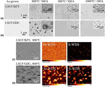
Figure 1 shows the surface microstructural evolution of LSCF thin films grown on (a) BZY and (b) GDC substrates before and after annealing at temperatures ranging from 800 to 1000 °C. The as-grown LSCF thin films show a relatively flat surface with no apparent surface precipitates. After annealing at 800 °C, both LSCF films on BZY and GDC substrates show surface precipitations. In the LSCF thin film on BZY, the precipitates are randomly distributed on the film surface with size ranging from 50–180 nm. In comparison, the LSCF thin film on GDC annealed at 800 °C shows a high density of surface precipitates with a grain size as large as 1.5 µm covering the entire cathode surface. Above 800 °C, no surface precipitation was observed but grain growth of LSCF, probably due to the sintering effect, as shown in the insets in Figs. 1(a) and 1(b). To determine the composition of the surface precipitates observed at 800 °C, SEM-WDS mapping of the LSCF films was performed as shown in Figs. 1(c) and 1(d). The presence of both Sr and S elemental compositions on the precipitates confirmed the formation of SrSO4. The SrSO4 formation is more severe in the LSCF film grown on GDC than on BZY, suggesting the influence of the electrolyte substrate on Sr-surface segregation.
Evolution of surface morphology of LSCF films on (a) BZY and (b) GDC substrates at varying annealing temperatures. The inset shows the high-magnification images of LSCF films after annealing. (c, d) SEM-WDS mapping of LSCF films after annealing at 800 °C for 300 h in air.

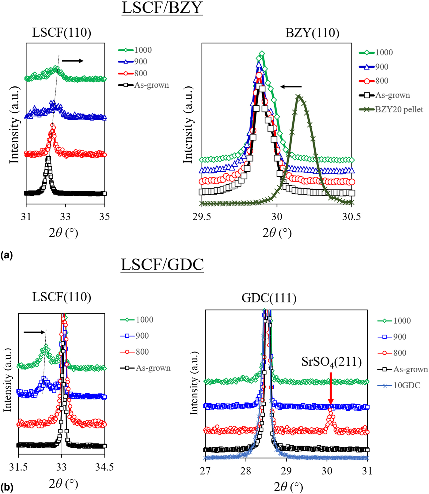
Figure 2 shows the XRD patterns of LSCF films on (a) BZY and (b) GDC substrates. The x-ray reflection peaks from 2θ = 20° to 80° can be found in the online Supplementary material (Fig. S1). Highlighted in Fig. 2 are the corresponding main peaks of LSCF and electrolyte phases. The LSCF films grown in BZY are highly crystalline with preferential orientation along (110). The (110) peaks of LSCF films gradually shift to higher angle accompanied by peak broadening and intensity reduction after annealing as shown in Fig. 2(a). The lattice constants of LSCF films were found to decrease with annealing temperature consistent with the shifting of the reflection peaks to higher angles (see Table S1 in the online Supplementary material). The lattice changes of LSCF suggest a possible chemical reaction between LSCF and BZY. The lattice constants of perovskite LSCF sensitively change with composition.[Reference Ten Elshof and Boejisma15] Moreover, the LSCF layer is thinner compared with BZY so that the interdiffusion through the interface gives rise to a more significant impact on changes in composition. On the other hand, the BZY (110) substrate peak shifted to lower angles in comparison with the bulk/pellet [Fig. 2(a)]. However, no further changes in the peak position of the BZY (110) peak were observed even after annealing at high temperatures. Compared with the SEM-WDS analysis, the XRD measurement was not able to detect the corresponding phase due to the SrSO4 formation. The crystallite size of LSCF film was evaluated from the full width at half maximum (FWHM) of the LSCF (110) peak using Scherrer's equation given by B(2θ) = Kλ/L cos θ where B is the FWHM and K = 0.98 (Scherrer constant). The evaluated values are given in Table S1 (online Supplementary material). Results show that the crystallite size of LSCF thin film increases from 35 to 98 nm after annealing at 800 °C. Above 800 °C, only a gradual increase in LSCF crystallite size was observed in a consistent manner with peak broadening and intensity reduction. This indicates that grain growth proceeds until a critical size is reached where both surface and interfacial energy are minimized.[Reference Chaudhari16]
XRD analyses of LSCF films on (a) BZY and (b) GDC substrates annealed at different temperatures. The XRD spectra of BZY and GDC pellet substrates are also shown as a reference. The lattice constant for BZY pellet substrate is a = 0.4212 nm and for GDC pellet a = 0.541 nm. The x-ray reflection peaks for the samples from 2θ = 20° to 80° is provided in the online Supplementary material (Fig. S1).

For the LSCF films grown on GDC substrates, the poorly crystalline (as-grown) film was crystallized after high-temperature annealing as shown in Fig. 2(b). The LSCF (110) peak appears after annealing at 900 °C with the minimal shift to higher angles. At 800 °C, the formation of SrSO4 is further confirmed by the appearance of reflection peaks corresponding to the celestine phase of SrSO4 (JCPDS no. 05-0593) with the preferential orientation along the (211). Compared with BZY, the reflection peak intensity and positions corresponding to the GDC substrate did not show considerable changes. This suggests that no significant reaction occurred between the LSCF phase and GDC during annealing.
The lattice constants of the LSCF layer and electrolyte substrates were evaluated to estimate the possible effects of interfacial strain (online Supplementary material, Table S1). The estimated lattice constants of the as-grown LSCF film is a = 0.55711 nm and c = 1.3656 nm, whereas for the BZY substrate, a = 0.42244 nm. The lattice mismatch is as large as 30% suggesting that the LSCF layer might not grow easily on the BZY substrate. However, XRD analysis reveals that the LSCF film grows readily on BZY with the preferential orientation along the (110) plane. This plausibly occurs via lattice coincidence site matching, where the geometrical coherence between the two planes with minimum misfit would correspond to the minimum elastic strain energy at the interface.[Reference Sasaki, Matsunaga, Ohta, Hosono, Yamamoto and Ikuhara17] In such a case, the lattice coincidence site is 4a LSCF = 3a BZY, with 4d(110)LSCF > 3d(110)BZY, such that the misfit is only −5.72% indicating compressive stress. The misfit was determined using δ = 2(l 1 − l 2)/(l 1 + l 2), where l 1 and l 2 are the interatomic distances along the parallel crystallographic axes of the two phases contained in the interface plane. The lattice coincidence model was also able to account for the orientational relationship for other heterointerfaces such as in Ni films on YSZ by PLD,[Reference Sasaki, Matsunaga, Ohta, Hosono, Yamamoto and Ikuhara17] and in metals on sapphire substrates[Reference Montesa, Shibata, Tohei, Ayikama, Kuromitsu and Ikuhara18] with large lattice mismatch.
Under compressive stress, grain growth appears to minimize interfacial energy (stress relaxation) favoring the growth of grains or texturing of the surface after annealing.[Reference Chaudhari16] This is consistent with the SEM observation and XRD analysis discussed in Figs. 1 and 2, suggesting that grain growth after annealing might relax the interfacial strain. Another possibility is the enhanced cation intermixing at high temperatures which would enable two incoherent layers to grow by forming a secondary phase at the interface. For LSCF films on GDC, the as-grown LSCF film is amorphous-like or poorly crystalline indicating the possible existence of a larger interfacial strain. Sufficient energy is needed to overcome large interfacial strain such that after annealing at high temperatures, the crystalline LSCF phase is formed.
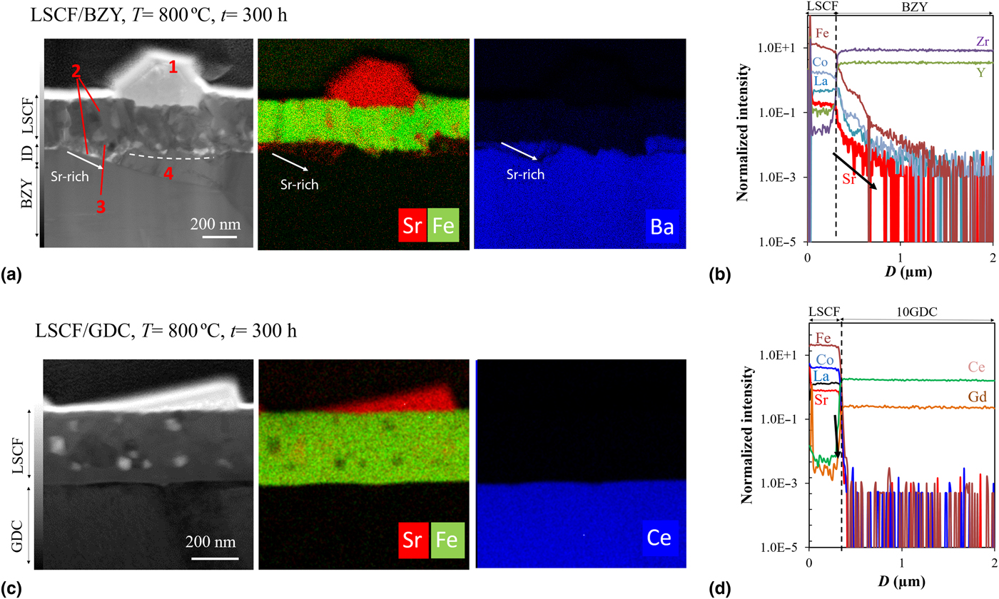
To characterize the Sr-segregation and possible reaction phases between the LSCF thin films and electrolyte substrates, STEM-EDS and SIMS analyses were performed as shown in Fig. 3. The STEM-EDS mapping of LSCF on the BZY substrate after annealing at 800 °C for 300 h is shown in Fig. 3(a). Various regions of the samples are labeled with (1), (2), (3), and (4) to elucidate the reaction products after annealing. Here: (1) SrSO4 precipitate, (2) nano-sized pores (inside the LSCF layer) and next to the region with interdiffusion products, (3) interdiffusion zone rich in Sr, and Y, and (4) another interface zone rich in La, Co, and Fe (please refer to Fig. S2). These results indicate that apparent inhomogeneous reactions took place and phase products were formed in the interface region between LSCF and BZY. In the vicinity of these reaction products, pores were formed, indicating that severe and selective mass transport took place across the interfaces, leaving pores at the original position of diffused cations. To further confirm the interdiffusion between the LSCF and BZY, SIMS analysis was performed as shown in Fig. 3(b). SIMS analysis indicates that the cations from LSCF diffused more preferentially into the BZY as compared with the GDC substrate (see online Supplementary material, Fig. S3) in the as-grown samples. In particular, broad cation diffusion profiles of Sr, Fe, Co, and La into BZY were observed. From the BZY side, Y diffused more actively than Zr as evidenced by the flat distribution of Y signal inside the LSCF layer.
STEM bright-field images with EDS composition distribution of Sr, Fe, Ba, and Ce; and SIMS analyses of LSCF films on (a, b) BZY and (c, d) GDC electrolytes after annealing at 800 °C for 300 h in air.

After annealing at 800 °C for 300 h, significant cation interdiffusion took place. Concentration profiles indicate some shoulder-like or plateau-like behavior in the interface and BZY side, suggesting that some drastic compositional change took place due to “secondary” phase formation. From the BZY side to the LSCF side, the Y component diffused into a whole region of LSCF, while the Zr and the Ba components stay without diffusion. This can be explained by the less thermodynamic stability of the Y component in BZY, which appears as a fact that when the composition is deviated toward the B-site rich side, the pure YO1.5 phase is precipitated as shown in the typical phase diagram behavior.[Reference Oyama and Yamaguchi13] From the LSCF side to the BZY side, Fe, Co, Sr, and La were diffused as suggested by STEM-EDS [in Fig. 3(a)]. Although the ionic size of Sr2+ is different from that of Ba2+, it is possible for Sr ions to occupy the A-site to form (Ba,Sr)(Zr,Y)O3, but there is still some tendency of two-phase separation into Sr-rich zirconate and Ba-rich zirconate; in Fig. 3 (also in Fig. S2), there can be seen some grains of Sr-rich and Ba-poor zirconate, Sr(Zr,Y)O3 and the rest parts with enriched Y is (Ba,Sr)(Zr,Y)O3. In Fig. 3(a), overlapping of the S and the Sr components suggests the SrSrO4 formation; interesting enough, in the same place Y is detected, suggesting the formation of solid solution between SrSO4 and Y2O2SO4. In addition to Y-rich BZY, La(Co,Fe)–O oxide seems to be formed, suggested from the SIMS elemental profile, although the concentration at the shoulder or the plateau is about one order of magnitude lower. Transition metals have been reported to be easily accommodated by the BaZrO3 perovskite oxide owing to it large lattice volumes.[Reference Polfus, Fontaine, Thorgensen, Riktor, Norsby and Bredesen19] The transition metals were found to aggregate throughout the grain and grain boundaries of BaZrO3. It is likely that the cations of LSCF diffused actively into the BZY side along the grain boundaries.
On the other hand, lanthanide dopants can substitute for Ba-site, and smaller trivalent dopants (as in this case Y) can preferentially substitute for Zr ions in the BZY system.[Reference Islam, Slater, Tolchard and Dinges20] Exact determination of Ba diffusion into LSCF from SIMS profiles was hardly made due to similarity of Ba isotopes (138Ba16O) to that of La (139La16O). Hence, SEM-WDS line-scan was performed. The WDS detector can correctly distinguish the spectral dispersion lines corresponding to Ba Kα = 32.194 keV and La Kα = 33.442 keV (see online Supplementary material, Fig. S4). Results show that La/Ba interdiffusion occurred even during the PLD growth and became more evident after prolonged annealing. From shape of profiles, it is suggested that main diffusion occurs through bulk (grains) as well as grain boundaries particularly at low temperatures. XRD analysis confirms the lattice expansion of BZY after the deposition of the LSCF thin film [see Fig. 2(a) and Table S1]. This result indicates that the cations from LSCF are accommodated in the BZY lattice by expansion. Above 800 °C, the transported Ba is possibly consumed by the formation of Ba-rich phases at the LSCF/BZY interface.
To investigate the interface reaction between LSCF film and GDC substrate, STEM-EDS and SIMS and analyses were also carried out as shown in Fig. 3(b). STEM-EDS also showed no evidence for the formation of Sr-rich secondary phase at the LSCF/GDC interface. Instead, a significant amount of SrSO4 formation on the surface and excessive pores were also observed. On the other hand, La, Co, Fe, and Sr exhibit essentially no transportation toward GDC as evidenced by a sharp drop of cation signals close to the LSCF/GDC interface in the SIMS profiles [Fig. 3(d)]. This is in contrast with the LSCF film grown on the BZY substrate where extensive chemical reactions or interdiffusion took place at the interface during annealing. Difference in Sr diffusion from LSCF into BZY or into GDC substrates may account for the difference in features of the SrSO4 formation. When some amount of the Sr component diffused into BZY, the thermodynamic activity of SrO in LSCF decreases so that the driving force for the SrSO4 formation correspondingly decreases. When no Sr diffusion occurs, the thermodynamic activity of SrO remains unchanged so that there remains strong driving force for the SrSO4 formation.
Summarized in Fig. 4 is the plausible interfacial reaction mechanisms between the LSCF and (a) BZY and (b) GDC substrates. Initially, cations from LSCF diffuse into BZY as shown in Fig. 4(a) (which can be inferred from the SIMS analysis). Annealing at high temperatures results in the consumption of Sr by BZY forming Sr-rich reaction products at the interface [Fig. 4(b)]. Hence, further Sr surface diffusion in LSCF is hindered. As discussed above, after long-term annealing the chemical reaction between LSCF and BZY has produced very complicated phases which include LaFeCo-rich phase, (Ba,Sr)(Zr,Y)O3 solid solutions, and Y-rich interface. These phases might be a result of the active diffusion of Sr into BZY to maintain charge balance. In most protonic SOFC, the LSCF is used in conjunction with BZY as a micrometer-thick porous composite electrode materials which show relatively good stability and excellent performance (prepared at high temperatures of 1000 °C, and operated for about 50 h).[Reference Ze, Lui, Wang, Choi, Zuo and Liu21, Reference Yang, Wang, Blinn, Liu, Liu, Cheng and Liu22] It is also worth noting that although STEM-EDS analysis showed a narrow reaction area of about 30–100 nm, SIMS measurement showed a much precise extent of interdiffusion zone which extends more than 1 µm into the inner parts of BZY from the LSCF/BZY interface although the concentration of diffused elements are quite small. It is likely that Sr-rich regions (and related reaction phase) may also exist in the case of the porous LSCF–BZY composite electrode, and if such regions are in the order of nanometer thickness, they would not be easily detected by SEM-EDS analysis.
Schematic diagram of the plausible reaction mechanism between LSCF films and (a, b) BZY and (c, d) GDC electrolyte substrates. The severe Sr-segregation and eventual reaction of Sr with SO2 in air are hindered by the dissolution and or diffusion of Sr into the BZY substrate. Sr-segregation however, is most preferred in LSCF on GDC since Sr diffusion toward GDC is highly inactive.

In the case of the LSCF film on GDC, the Sr diffusion into GDC is very limited. Instead, Sr is segregated out of LSCF to the surface and is consumed by the reaction with the SO2 impurity in air to form SrSO4. The chemical reactions occurred mainly on the cathode surface rather than at the LSCF/GDC interface. The SrSO4 formation can be described by the following chemical reaction:
 $${\rm SrO}\,({\rm in\ LSCF}) + {\rm S}{\rm O}_2 + 0.5{\rm O}_{\rm 2} = {\rm SrS}{\rm O}_4$$
It has been reported that sulfur poisoning of LSCF would result in the simultaneous formation of Co–Fe spinel phases because the A-site deficient composition is not stable in LSCF.[Reference Wang, Yamaji, Cho, Shimonoso, Kishimoto, Brito, Horita and Yokokawa4, Reference De Vero, Develos-Bagarinao, Lui, Kishimoto, Ishiyama, Yamaji, Horita and Yokokawa23] The growth of LSCF thin films by PLD tends to provide the A-site excess composition; in such a case, excess A-site component, namely SrO, reacts to SO2 to form SrSO4.[Reference De Vero, Develos-Bagarinao, Lui, Kishimoto, Ishiyama, Yamaji, Horita and Yokokawa23–Reference Cai, Kubicek, Fleig and Yildiz25] The current results show an interesting feature that reactivity of LSCF with the substrate can also control the reactivity of the SrO component with SO2. It is also important to note that at high temperatures no apparent formation of SrSO4 was observed. Since the partial pressure of SO2 in the present investigation is extremely low because of the use of artificial air, no formation at high temperature can be reasonably interpreted from the equilibrium point of view. At high temperatures, frequently Ostwald ripening of SrSO4 is observed, indicating the volatilization and recondensation becomes important at higher temperature. Even so, it is not likely that no SrSO4 formation is due to kinetic reason based on high volatilization.
Another interesting observation is that the Sr transportation in heterointerfaces consisting of perovskite–perovskite structures appears highly favorable than in the perovskite–fluorite interfaces. This can be plausibly due to a smaller activation energy need for cations to migrate or occupy lattice sites in neighboring perovskites than in fluorite substrates.[Reference Izuki, Brito, Yamaji, Kishimoto, Cho, Shimonosono, Horita and Yokokawa8] The reaction between different layers depends on the lattice symmetries of the two adjacent phases. For instance, an active mass transport was observed in different perovskite–perovskite oxide diffusion couples such as in La0.8Sr0.2CoO3 and La0.8Sr0.2FeO3,[Reference Kishimoto, Sakai, Horita, Yamaji, Brito and Yokokawa26] La0.6Sr0.4CoO3−δ, and La0.8Sr0.2Ga0.8Mg0.2O2.8,[Reference Horita, Yamaji, Sakai, Yokokawa, Weber and Ivers-Tiffee27] and the richly reactive LSCF and LSGM systems.[Reference Wang, Yamaji, Cho, Shimonosono, Kishimoto, Brito, Horita and Yokokawa3] For cubic fluorite systems, it has been commonly observed that solid solutions can be easily formed between the stabilized zirconia and the ceria-based oxide in the fluorite structure especially at high temperatures.[Reference Eguchi, Akasaka, Mitsuyasu and Nonaka28, Reference Tsoga, Gupta, Noumidis and Nikopoulos29]
Izuki et al. estimated the apparent Sr bulk diffusivity in GDC showing a value of about 10−21 m2/s corresponding to a diffusion length of 2 nm at 1000 °C.[Reference Izuki, Brito, Yamaji, Kishimoto, Cho, Shimonosono, Horita and Yokokawa8] In a similar manner, the Sr apparent bulk diffusivity in BZY at 1000 °C was estimated by fitting the SIMS Sr depth profile (details in the online Supplementary material) with the Crank's equation[Reference Crank30] given by:
 $$\displaystyle{{X-X_0} \over {X_{\rm s}-X_0}} = 1-{\rm erf}\left( {\displaystyle{z \over {2\sqrt {D_{{\rm app}}t}}}} \right)$$
Here, X is the normalized intensity of the secondary ion, X s is the intensity at the surface (z = 0), and X 0 is the intensity at the background. The apparent Sr diffusivity in BZY is about 1.18 × 10⁻¹⁹ m2/s which is two orders of magnitude faster than in GDC under the same annealing conditions (diffusion length of about 190 nm). Considering that a thicker layer reaction area was observed by SIMS analysis (more than 1 µm from the LSCF/BZY interface), we infer that the Sr may further diffuse into the inner parts of BZY via grain boundaries.
Lastly, the difference in the Sr diffusion behavior in GDC and BZY electrolyte substrates may lead to the difference in the SrO solubility and the SrO thermodynamic activity in LSCF. The cation diffusion flux, J can be written as:
 $$J = cB\; \displaystyle{{{\rm d}\mu} \over {{\rm d}x}}$$
where c is the concentration of diffusing species, B the mobility, and dμ/dx is the chemical potential gradient of the diffusing species. In the bulk diffusion, both concentration and the driving force are critical. Note that the chemical potential in the LSCF system changes drastically when composition changes across the line of A/B ratio = 1, whereas the Sr content does not give rise to large changes. Based on the SIMS analysis, Sr from the LSCF initially diffused in BZY which is not the case in GDC electrolyte. This result indicates that the Sr concentration of the cathodes may vary at the interface and consequently change the SrO activity. The SrO activity on the cathode side provides a steeper chemical potential gradient in promoting dissolution of SrO into the BZY electrolyte. Consequently, provides a large flux of SrO into the BZY electrolyte. The possible implication of the reaction products formed between the LSCF and BZY on the electrochemical properties of LSCF cathodes are suggested for further studies. In the case of LSCF in GDC, segregated Sr from LSCF readily reacts with SO2 in air forming severe SrSO4 on the surface. This leads to the lowering of the SrO activity in the LSCF perovskite. Hence, the Sr reaction with SO2 in air decreases the driving force for the diffusion of Sr in GDC. The severe accumulation of SrSO4 formation on the active surface of LSCF and or electrochemical actives sites was reported to result in rapid cathode performance degradation.[Reference Wang, Yamaji, Cho, Shimonoso, Kishimoto, Brito, Horita and Yokokawa4, Reference De Vero, Develos-Bagarinao, Lui, Kishimoto, Ishiyama, Yamaji, Horita and Yokokawa23]
Conclusions
In summary, we demonstrated that the cation interdiffusion between the cathode and the electrolytes affects the Sr-surface segregation and/or the formation of SrSO4. The LSCF films grown on BZY substrates exhibit reduced formation of SrSO4 as compared with the LSCF films grown on GDC after annealing at 800 °C. The reduced SrSO4 formation was associated with the driving force for Sr diffusion to form Sr-rich phases at the LSCF/BZY interface. On the other hand, Sr from the LSCF showed inactive diffusion toward GDC. Instead, the Sr from the LSCF mainly segregated on the surface and reacted with the SO2 in air forming SrSO4. Hence, the reaction mainly took place on the surface due to the driving force for SrSO4 formation. These results suggest that the Sr segregation in the LSCF cathode is a competing effect between surface reaction with the impurities in air (such as SO2) and chemical reaction with the electrolyte substrate. This interesting feature is in parallel with the feature difference between the A-site excess and the stoichiometric LSCF. In order to overcome the sulfur and other poisoning phenomena, it becomes essential to control the composition of LSCF materials. From this feature, an important point can be derived as follows: when the LSCF cathode reacts with the substrate, the composition of LSCF changes and deviates from the initially designed one. If the stability of LSCF should be kept even after the fabrication of applying LSCF films on the substrate, it becomes essential to avoid such reactions and resulting composition changes. Since it seems much easier to control the composition of LSCF compared with control of compositional changes on interface reactions, it is suggested, in addition to the optimization of cathode composition, to control the cathode–electrolyte interface so as to minimize the compositional changes by suitable modification or engineering of the active cathode–electrolyte interfaces.
Supplementary material
The supplementary material for this article can be found at https://doi.org/10.1557/mrc.2018.208.
Acknowledgments
This work is supported in part by the New Energy and Industrial Development Organization (NEDO) project, “Basic study on the rapid evaluation method of SOFC durability”.