
Introduction
The electric cell–substrate impedance sensing (ECIS) is a noninvasive method used to investigate living cells spectroscopically in real time, pioneered by Keese and Giaever.[Reference Giaever and Keese1] ECIS has a wide variety of applications, including monitoring cell proliferation, migration, and wound healing, replacing traditional methods such as scratch assays, and records reproducible and quantitative data.[Reference Keese, Wegener, Walker and Giaever2] The electrical properties of cells are highly sensitive to small changes in their morphology and function. These changes can be measured while cells are growing directly on the electrodes. The common electrodes are made of a thin structured gold layer, which do not allow high-resolution imaging of the cells by inverse microscopy. Taking advantage of parallel optical microscopy with electrical measurements, the complementary data lead to a deeper understanding of cell events that can be captured electrically or optically.[Reference Ramuz, Hama, Huerta, Rivnay, Leleux and Owens3] Transparent conducting electrodes can provide new advances and possibilities in this field.
Carbon nanotubes (CNTs), originally introduced by Iijima,[Reference Iijima4] represent a remarkable combination of properties such as conductivity, mechanical strength and flexibility, transparency, feasibility for chemical modification, and biocompatibility.[Reference Tîlmaciu and Morris5] One of the main application of this organic material is in the development of electrochemical biosensors for the detection of various biomolecules. In recent years, several research groups have developed these nanostructured biosensors with the focus on the detection of cancer cells. For instance, CNTs were vertically aligned on nickel-interdigitated microelectrodes and patterned on the silicon-based substrate for the rapid detection of SW48 cells.[Reference Abdolahad, Taghinejad, Taghinejad, Janmaleki and Mohajerzadeh6] This sensor was later modified with amine groups and folic acid for a sharper electrical response in the detection of lung cancer cells.[Reference Zanganeh, Khodadadei, Tafti and Abdolahad7] CNTs have been also deposited on ITO-coated glass using a layer-by-layer assembly technique and linked to cell-specific epithelial markers.[Reference Liu, Zhu, Dan, Fu and Liu8] The impedances were measured by the immersion of sensor in HepG2 cell suspensions for the maximum duration of 90 min. This sensor improved the speed and sensitivity of target cell detection, taking advantage of the large specific surface area and good conductivity of CNTs. A CNT-based biosensor has been also developed for bacterial detection.[Reference Andrade, Nascimento, Oliveira, De Oliveira, De Melo, Franco and Oliveira9] This biosensor was made of multi-walled carbon nanotubes (MWCNTs) drop-coated on a cysteine-modified gold electrode using chemistry crosslinking reactions. MWCNTs were coated with antimicrobial peptide for the effective detection of different categories of bacteria in concentrated suspensions. The resulting biosensor showed low limits of detection and a good selectivity compared to traditional complex measurements.
In this report, we developed an ECIS electrode array made of a uniform single-walled carbon nanotube (SWCNT) film with sheet resistance (Rs) of 269.9 Ω/sq and transmittance of 72.8%. The SWCNT electrodes were directly spray-coated on a flexible transparent polymeric substrate without further modifications with binding biomarkers. The type of CNT and dispersant highly affected the optical and the electrical properties of the electrode. Our electrodes highly enhanced the quality of optical imaging by inverse microscopy compared to the gold electrodes. The impedimetric monitoring was performed during proliferation and migration of MCF7 cells up to 35 h. The recordings were directly comparable to the recordings done with a gold electrode.
Materials and methods
The dispersants such as sodium dodecyl sulfate (SDS) and carboxymethyl cellulose (CMC) were dissolved in deionized (DI) water with 1 and 0.5 wt% concentrations, respectively. SWCNT (Carbon Solutions, Inc., California, USA) suspensions were prepared in SDS and CMC solutions with 0.03 wt% final concentration in both dispersants. The MWCNTs (Hanos CM–250, Hanwha Chemical, Seoul, South Korea) were mixed in SDS solution to obtain a final concentration of 0.1 wt%. The CNT suspensions were horn sonicated in an ice water bath alternating between 200 and 120 W in 5 min intervals for a total time of 30 and 15 min for SDS and CMC dispersants, respectively. They were centrifuged at a speed of 15,000 rpm for 1.5 h, then 80% of the suspension was decanted and stored at room temperature (RT) before use.
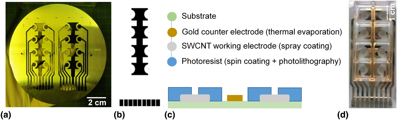
A corona-treated cyclic olefin polymer (treated-COP) foil was selected as a substrate for the electrode arrays, on which a gold electrode array was deposited by thermal evaporation using the shadow mask shown in Fig. 1(a). The working electrode areas were etched away by gold etchant and spray coated with the SWCNT CMC-based film. In a study done by Chen et al., gold has shown the best work function matching to SWCNTs.[Reference Chen, Jin, Wei, Li, Liu, Wang, Zhang, Liao, Hu, Song and Zhang10] For the CNT films used in the characterization studies, MWCNTs and SWCNTs were spray coated onto 2.5 × 2.5 cm2 treated-COP substrates.
(a) The shadow mask used for thermal evaporation of gold and spray coating of SWCNT onto the treated-COP substrate; (b) the shadow mask used in photolithography; (c) the cross-section schematic of the fabrication process of SWCNT electrode arrays; and (d) the electrode array made of SWCNT working electrodes.

For spray coating, an industrial air atomizing spray valve (Nordson EFD, USA) mounted on an automated overhead motion platform was used to generate fine droplets of a water-based CNT ink. Spray parameters such as atomizing nitrogen gas pressure, orifice opening, material pressure, and distance of spray gun to substrate were optimized in other studies to obtain uniform CNT layers.[Reference Loghin, Colasanti, Weise, Falco, Abdelhalim, Lugli and Abdellah11] Substrates were heated up to 63 and 80 °C during spray coating of CNT suspensions with SDS and CMC dispersants, respectively. After spray coating, samples were immersed in DI water for 30 min and dried at 40 °C for 10 min. The SWCNT CMC-based films were immersed in a solution of nitric acid (HNO3):DI water (1:4) overnight. Then, they were dried at 70 °C, washed for 5 min in DI water, and heat-treated at 90 °C for 2 h to remove any possible remaining CMC residues.
The whole electrode array, except the covered SWCNT films, was plasma treated for 12 s at an oxygen pressure of 0.4 mbar and generator power of 90 W using a Femto low-pressure plasma system (diener electronic GmbH, Ebhausen, Germany). Afterwards, photoresist SU8-2 (MicroChem Corp., Massachusetts, USA) was spin coated onto the array (1000 rpm), followed by a soft-baking process. The array was exposed to UV light (360 nm) with exposure energy of 90–105 mJ/cm2 using the photolithography masks shown in Fig. 1(b). Subsequently, the photoresist was post-baked and soaked in developer mr-Dev 600 (micro resist technology GmbH, Berlin, Germany) for 70 s. Finally, the arrays were washed with isopropyl alcohol and blow-dried. The thickness of SU8-2 was 4.1 µm and the working electrode had a diameter of 244.5 (±8.87) µm (n = 10). The fabrication process of the electrode array is summarized in Fig. 1(c). For ECIS measurements, a sticky-Slide 8 Well (ibidi GmbH, Munich, Germany) was mounted on the electrode array shown in Fig. 1(d).
Characterization of carbon nanotube films
Absorbance spectroscopy and sheet resistances
Transmittance spectra of CNT films were recorded in the wavelength range of 300–1000 nm using a 300 W xenon arc lamp. The light was chopped at a frequency of 210 Hz and passed through an Oriel Cornerstone™ 260 1/4 m monochromator. The monochromatic light was then directed onto a calibrated photodiode with a transductance amplifier that was connected to an Oriel Merlin digital lock-in amplifier. The amplified signals were analyzed with the data acquisition and spectroscopy software TracQ™ Basic. A transmittance spectrum of a treated-COP foil was recorded as a reference to determine the pure transmission of CNT films. The sheet resistances were recorded using a four-point probe head (Jandel, Leighton Buzzard, UK) connected to a Keysight B2901A source measuring unit. For all the measurements, a constant current of 100 µA was sourced. All the measurements were performed at RT (Supplementary Fig. S1).
Scanning electron microscopy
Scanning electron microscopic (SEM) images were taken from CNT films with different transmittances. The images were recorded with a field-emission scanning electron microscope (NVision40, Carl Zeiss Microscopy GmbH, Jena, Germany) at an acceleration voltage of 7 kV and an extractor voltage of 5 kV. The working distance was adjusted in a range of 5–5.5 mm for best image quality.
Cell culture
Viability assay
MCF7 breast adenocarcinoma cells (CLS GmbH, Eppelheim, Germany) were cultured in RPMI 1640 medium supplemented with 10% fetal bovine serum. MCF7 cells were seeded on SWCNT CMC-based electrodes (269.9 Ω/sq and 72.8% transmittance) with an initial cell concentration of 2 × 10⁴ cells/cm2 and incubated at 37 °C in a 5% CO2 atmosphere. Fluorescein diacetate (FDA) and propidium iodide (PI) were used to stain the viable and nonviable cells, respectively. After 3 days, cell culture medium was removed and cells were washed with PBS. FDA (19 µM) and PI (30 µM) in RPMI 1640 (supplemented with 200 mM L-glutamine without phenol red) were added to the cells and incubated at RT for 4 min. The staining solution was washed away with PBS and replaced by RPMI 1640 without phenol red. Afterwards, images were taken with a Nikon ECLIPSE Ti inverse microscope.
Immunofluorescence assay
MCF7 cells were cultured on SWCNT CMC-based electrodes (269.9 Ω/sq and 72.8% transmittance) and gold electrodes of ECIS® cultureware with an initial concentration of 7 × 10⁴ cells/cm2. After 1 day, cells were fixed with formalin solution for 30 min at RT. For permeabilization, PBS containing 0.1% Triton X-100® and 10% (v/v) FCS was added to the cells for 30 min. Cells were blocked with PBS containing 1% bovine serum albumin (BSA) and 0.2% Triton X-100® to avoid nonspecific antibody bindings. Samples were incubated with monoclonal mouse anti-α-tubulin (1 µL/mL) in 1% BSA–0.05% Triton X-100®–PBS overnight at 4 °C. Afterwards, cells were incubated in anti-mouse IgG-Atto 594 secondary antibody (1 µL/mL) and 4′,6-diamidino-2-phenylindole (DAPI) in 1% BSA–0.05% Triton X-100®–PBS at RT for 1 h. Cells were washed with PBS and stored in PBS during imaging.
ECIS measurements
On SWCNT CMC-based electrode array, MCF7 cells were seeded with an initial concentration of 15 × 104 cells/cm2 in wells pre-coated with collagen IV. To combine ECIS measurements with live cell imaging, a custom specific array station suitable for electrical contacting and optical microscopy was designed. The electrode arrays were placed inside the array holder which was connected to the ECIS Zθ station controller (Applied BioPhysics, Inc., New York, USA). The array holder was located on the imaging stage of a Nikon ECLIPSE Ti microscope and connected to the Heating & Gas Incubation System (ibidi GmbH, Munich, Germany) to provide the required temperature of 37 °C and 5% CO2. The cell-free electrodes were used as controls. The culture medium supplemented with 1% Pen/Strep solution was used as the electrolyte. The impedance measurements and the optical imaging of cells were conducted simultaneously. ECIS® cultureware 8W1E was used as a control array.
Results and discussion
Optical and electrical properties of CNT films
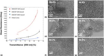
Transmittance and Rs of transparent conducting films must be considered in parallel when trying to achieve a good trade-off between the electrical conductivity and the optical transmittance of electrodes. The CNT type and dispersant both affected the Rs and transparency of the final CNT films [Fig. 2(a)]. The sheet resistances of SWCNT films were lower than those of MWCNTs at the same transmittances. The average diameter of the MWCNTs used in this study was 10–15 nm, i.e., substantially higher than the average diameter of SWCNTs (1.1 nm). The larger diameter of MWCNTs increased their light absorption. However, the charge transfer mainly occurs on the outermost layer of MWCNTs at small currents and is not efficient at increasing conductivity.[Reference Chen, Chen and Chang12] Also, the transmittance of CNT films decreased with the decreasing Rs, as there were more CNTs coating the substrate at lower transmittances.
(a) The Rs (n = 15) of CNT films as a function of the transmittance (n = 3) at a wavelength of 550 nm. Error bars represent the standard deviation of each group. SEM images of (b,c) MWCNT SDS-based, (d,e) SWCNT SDS-based, and (f,g) SWCNT CMC-based films spray coated on the treated-COP substrate. All the CNT films were imaged after removal of the dispersants. The transmittance of each film is shown next to the label.

For a quantitative comparison of CNT films, Rs values and transmittances [Fig. 2(a)] were fitted in Matlab to the Tinkham's formula (1):[Reference Tinkham13]
 $${\it T} = \left( {1 + \displaystyle{{Z_0} \over {2R_s}}\displaystyle{{\sigma_{{\rm op}}} \over {\sigma_{{\rm dc}}}}} \right)^{-2}$$
in which T and Rs stand for transmittance and sheet resistance, respectively. Z 0 is the impedance of free space and equal to 120 π. The σ dc stands for the electrical conductivity (assumed to be independent of thickness) and σ op represents the optical conductivity of the CNT layers. The ratio between the latter two parameters (σdc/σop) is referred as a figure of merit ɤ, which enables the comparison of the performance of CNT layers.[Reference Falco, Cina, Scarpa, Lugli and Abdellah14] The SWCNT CMC-based film had the highest figure of merit ɤ, which indicates that at a given transmittance, the SWCNT CMC-based film has a lower Rs compared to the CNT SDS-based films.
A good trade-off between Rs and the transmittance of CNT films was achieved with the CMC-based films having 269.9 Ω/sq at 72.8% transmittance. Before the acid treatment, the SWCNTs were encapsulated by an electrically insulating polymer matrix of CMC.[Reference Fujigaya and Nakashima15] In a final washing step, HNO3 immersion was used to remove CMC from the SWCNT films. Due to the CMC removal, the thickness of SWCNT film is reduced and CNT–CNT junctions are formed in an electrical percolation network, resulting in highly conductive film.[Reference Tenent, Barnes, Bergeson, Ferguson, To, Gedvilas, Heben and Blackburn16] The subsequent heat treatment significantly removed weakly adsorbed dopants. This has been shown in previous work, where Raman spectroscopy was performed prior to and after heat treatment, and showed an effective removal of HNO3.[Reference Loghin, Colasanti, Weise, Falco, Abdelhalim, Lugli and Abdellah11]
Surface topography of CNT films
MWCNT SDS-based films showed an insufficient coverage at 88.8% transmittance, whereas the substrate was mostly covered for 66.8% transmittance [Figs. 2(b) and 2(c) and Supplementary Fig. S2]. SWCNT SDS-based layers agglomerated and formed a network of bundles on the substrate. The substrates were not uniformly covered by SWCNT at 65.5% transmittance [Figs. 2(d) and 2(e)]. This could be due to the fact that SWCNTs were not well dispersed in water before spray coating. The CNTs have hydrophobic surface and they strongly stick together in water due to the van der Waals forces.[Reference Zhou and Azumi17] The adsorption of SDS on the surface of SWCNT is based on the hydrophobic reactions between the hydrophobic tail of SDS with SWCNT.[Reference Vaisman, Wagner and Marom18] Consequently, the formation of SDS micelles in water can disfavor the separation of SWCNT bundles in aqueous solution. Contrarily, CMC can bridge adjacent SWCNT via a polymer wrapping mechanism and the presence of carboxymethyl groups (–CH2–COOH) on CMC enhances the solubility of CMC in water.[Reference Falco, Cina, Scarpa, Lugli and Abdellah14] SWCNT CMC-based layers formed a uniform film on the substrate already at 89.2% transmittance [Figs. 2(f) and 2(g)]. SWCNTs were better dispersed in water by CMC compared to SDS, leading to more uniform SWCNT films on the treated-COP substrate.
Optical microscopy on CNT electrodes
The cell–substrate interactions play an important role in cell morphology as well as in cellular behavior.[Reference Imaninezhad, Schober, Griggs, Ruminski, Kuljanishvili and Zustiak19,Reference Lee, Ryu, Kim and Kim20] In the absence of ECM proteins, L929 cells had round morphologies and MCF7 cells attached loosely on the photoresist surface [Supplementary Figs. S3(a) and S3(b)]. MCF7 cells adhered better on the uncoated SWCNT, although the part of cell layers could still be washed away [Supplementary Fig. S3(c)]. This could be explained by the adsorption of proteins that are available in serum-supplemented medium or secreted by cells onto the CNTs.[Reference Imaninezhad, Schober, Griggs, Ruminski, Kuljanishvili and Zustiak19] Pre-coating of SWCNT and photoresist with collagen IV enhanced the attachment of cell layer significantly and the cell layer was not disturbed during the staining process. It has been previously shown that the pre-absorption of ECM proteins on CNTs facilitates the early cell attachment and spreading.[Reference Imaninezhad, Schober, Griggs, Ruminski, Kuljanishvili and Zustiak19]
Further studies have shown that the aligned orientation of CNTs on the substrate promoted the differentiation and proliferation of human mesenchymal stem cells,[Reference Namgung, Baik, Park and Hong21] the morphology of cardiomyocytes, as well as their electrical signal propagation.[Reference Ren, Xu, Chen, Li, Guo, Zhao, Wang, Zhang, Peng and Li22] The nanometer surface roughness,[Reference Price, Ellison, Haberstroh and Webster23] large specific surface area,[Reference Perepelytsina, Ugnivenko, Dobrydnev, Bakalinska, Marynin and Sydorenko24] high binding affinity to biological molecules,[Reference Namgung, Kim, Baik, Lee, Nam and Hong25] and possibility for topological modification[Reference Namgung, Baik, Park and Hong21,Reference Rahman, Najaf, Mehmood, Bilal, Shah, Mian and Ali26] make CNTs a suitable substrate for cell attachment and growth.
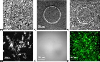
The underlying substrate influences not only the cell–substrate interactions but also the quality of images that are captured from cells. In phase contrast images of L929 cells, scattered dark spots were visible on SWCNT SDS-based electrodes [Fig. 3(a) and Supplementary Fig. S4]. Also with fluorescence microscopy, we could observe irregular lines on nuclei and cytoplasm of cells grown on SWCNT SDS-based films [Fig. 3(b) and Supplementary Fig. S5]. We identified those opaque line artifacts as bundles of CNTs deposited on the substrate. In comparison, the morphology of the MCF7 cells was not clearly visible on gold electrodes with phase contrast microscopy [Fig. 3(c)]. Due to the low transmittance of gold, higher light source intensities were required during imaging. The fluorescence images were blurred and the reflection of the fluorescence light on its way through the gold was weak in inverse microscopy [Fig. 3(d)].
(a) The phase contrast image and (b) the fluorescence image of L929 cells grown on the SWCNT SDS-based film (693.7 Ω/sq at 65.5% transmittance). (c) The phase contrast image and (d) the fluorescence image of MCF7 cells grown on the gold electrode. (e) The phase contrast image and (f) the fluorescence image of MCF7 cells grown on the SWCNT CMC-based electrode array (269.9 Ω/sq at 72.8% transmittance). The live cells are shown in green and the dead cells in red.

The dark spots and lines that were observed on SWCNT SDS-based films did not appear in phase contrast or fluorescence images of SWCNT CMC-based film [Fig. 3(e)]. The uniformity of SWCNT CMC-based films was a key factor in avoiding the artifacts and allowed for more detail studies in parallel with impedimetric measurements. Also, we verified the biocompatibility of the film, as more than 99% of cells grown on the CMC-based electrode and the photoresist were viable [Fig. 3(f)].
Impedimetric measurement of cell growth
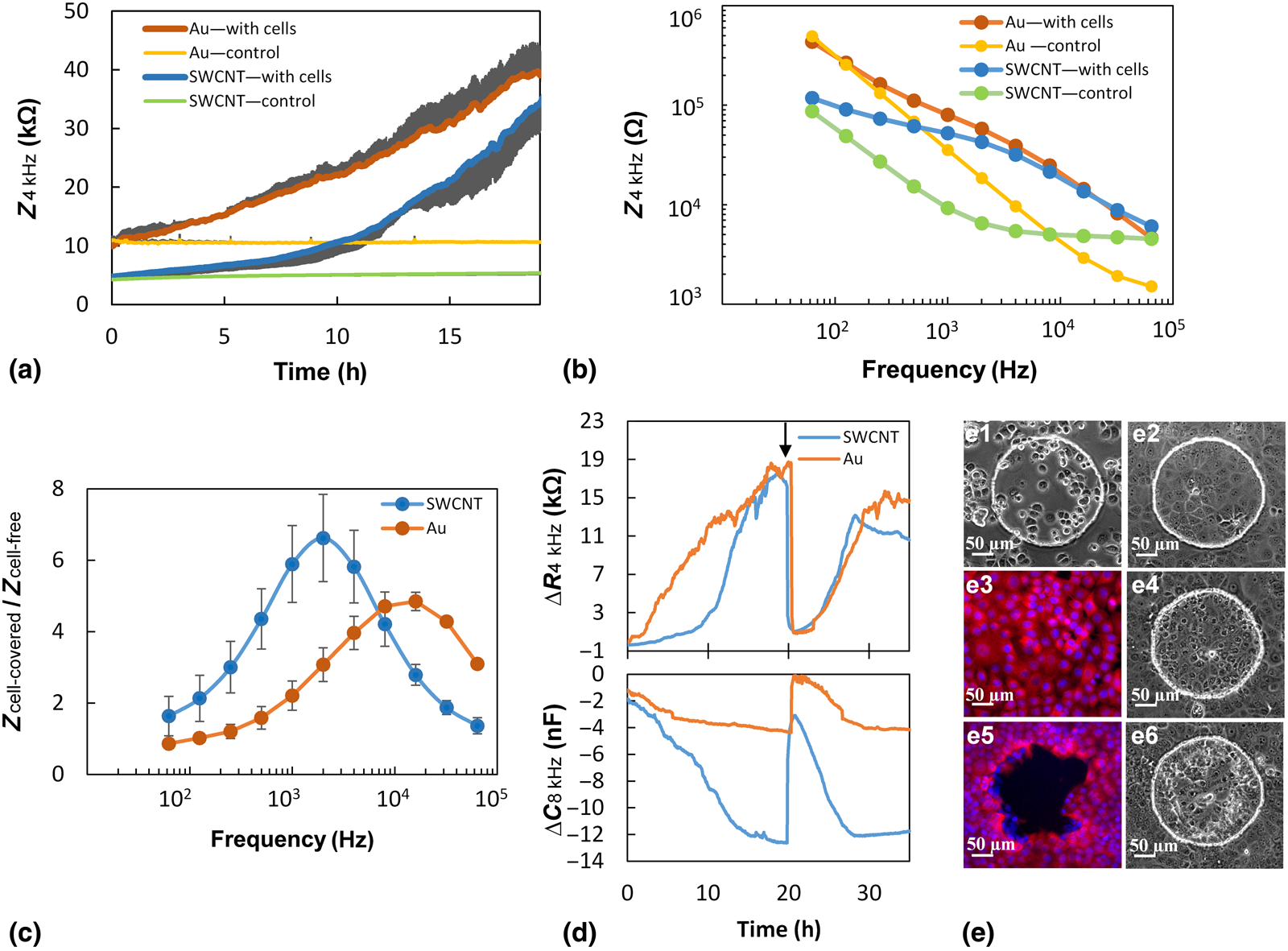
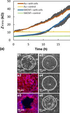
In ECIS measurement, a 1 V alternating current is applied through a 1 MΩ resistor between working and counter electrodes at different frequencies. While cells grow on the electrodes, the impedance values are recorded from the changes in voltage across the electrodes by Ohm's law. As first demonstrated by Warburg,[Reference Warburg27] the cell-free electrode in contact with the electrolyte can be described as a resistor and a capacitor in series. Later, Wegener et al.[Reference Wegener, Keese and Giaever28] developed this model for a cell-covered electrode which indicates that the current flow is restricted by junctions between cells and the cell–substrate contact regions. Also at high frequencies, the current considerably couples capacitatively across the cell membrane and the capacitance dominates the impedance spectra. In Figs. 4(a) and 4(b), we demonstrated the impedance spectra of gold and SWCNT electrodes as a function of time and frequency. The size of electrodes was equal and the same initial cell concentration was used for both groups. The attachment and growth of cells on both electrodes increased the impedances compared to the impedance of cell-free electrodes over 19 h. The cell-free SWCNT electrodes showed lower impedances compared to the cell-free gold electrodes at frequencies <8 kHz. At low frequencies of 62.5 Hz, the impedance was dominated by the high resistance of electrode at the electrode–electrolyte interface, which is in agreement with previous reports.[Reference Wegener, Keese and Giaever28] In the high frequency end, the impedance values tend to flatten out when the constriction resistance dominates and the impedance becomes frequency-independent.[Reference Stolwijk, Matrougui, Renken and Trebak30] For frequencies in between, the impedances represent a more specific median value for intra- and extra-cellular pathways.
(a) Impedance spectra of the gold electrode [with cells (n = 4) and without cells (control, n = 4), with only a plus standard deviation (SD)] and the SWCNT CMC-based electrode [with cells (n = 4) and control (n = 4), with only a minus SD] over 19 h. (b) The impedance spectra as a function of frequency measured 19 h (after cell seeding) for the cell-free control electrodes and the fully cell-covered electrodes. (c) The symbol (●) shows the average normalized impedances of gold and SWCNT electrodes measured 19 h after cell seeding by the impedance division of cell-covered electrodes (n = 4) to the cell-free electrodes (n = 4); (d) the differences in the resistance and the capacitance values of SWCNT CMC-based and gold electrodes (with cells) from control electrodes in the wounding assay. The arrow shows the time-point of wounding. (e) Microscopy images of MCF7 cells grown on the SWCNT electrode at different time-points during the wounding assay. In (e3,e5), the microtubules were stained with anti-mouse IgG-Atto 594 (shown in red), and the nuclei were stained with DAPI (shown in blue).

The most relevant and sensitive frequencies were selected before the domination of constriction resistance where the cells can still act as insulating particles.[Reference Giaever and Keese1] The normalized impedance of each electrode was calculated at different frequencies, to find the frequencies for sensitive impedance monitoring [Fig. 4(c)]. The SWCNT electrode showed the maximum normalized impedance of 6.6 at 2 kHz, and the gold electrode showed the maximum ratio of 4.8 at 16 kHz. We correlate this behavior to the higher capacitance of the SWCNT electrode, as the normalized resistance of SWCNT was lower than that of the gold electrode at frequencies higher than 250 Hz [Supplementary Figs. S6(a) and S6(b)]. This higher sensitivity of CNTs could be due to the larger specific surface area of CNTs compared to the gold electrode.[Reference Aval, Ghoranneviss and Pour29] The resistance of both electrodes was more dominant at lower frequencies of about 1 kHz, while the capacitance was more dominant at higher frequencies after 8 kHz [Supplementary Figs. S6(c) and S6(d)]. We chose the frequency of 4 kHz to monitor the impedance graphs, as it belonged to the most sensitive frequency range of both electrodes. Based on previous studies, the cell type and the electrode design influence the range of sensitive frequencies.[Reference Stolwijk, Matrougui, Renken and Trebak30]
In the next step, we aimed to perform the wounding assay with the SWCNT electrode. Figure 4(d) represents the differences in resistance and capacitance (real and imaginary part of impedance) of SWCNT and gold electrodes in the presence of MCF7 cells for 35 h. The respective changes are followed by the microscopy images shown in Fig. 4(e). The resistance of both electrodes increased during the cell proliferation, until they reached the peak when the surfaces of working electrodes were fully covered with cells [Fig. 4(e1–e3)]. Simultaneously, capacitances decreased to a minimum peak for fully cell-covered electrodes, as the cell coverage on both electrodes was increasing. The MCF7 cells are motile and the micro-motion of cells on the electrodes created the fluctuations especially in resistance values, which has been previously observed for gold electrodes.[Reference Keese, Wegener, Walker and Giaever2] Afterwards, a wounding current of 1.4 mA for 40 s was applied to kill the cells on working electrodes. The high current perforated the cell membranes and cells lost their integrity [Fig. 4(e4)]. The resistance of both samples decreased to values close to the resistance of the control electrodes, despite the presence of dead cells on the electrodes and the cell debris in medium. Afterwards, cells surrounding the working electrode started to recover the cell-free wounded area [Figs. 4(e5) and 4(e6)] and the resistances increased again until they reached the maximum values for fully cell-covered electrodes.
Conclusions
We have developed SWCNT-based electrodes on a flexible polymeric substrate to perform ECIS measurements in parallel with optical imaging. We achieved uniform SWCNT electrodes using CMC dispersant with a good trade-off Rs (269.9 Ω/sq) at 72.8% transmittance. The uniformity of electrode surface and its high transparency allowed for the improved optical imaging quality of cells. We correlated the impedance data with optical images which enhanced the understanding of the spectroscopic data in detail. To highlight this benefit, the effect of wounding current on cell morphology and perforation of the cell membrane was visualized for cells grown on SWCNT electrodes by inverse microscopy. The impedimetric monitoring of cell proliferation and migration was successfully performed by the SWCNT electrode and compared with the gold electrodes. The recordings indicated that SWCNT had higher normalized impedance compared to the gold electrodes at various frequencies. This was due to the higher capacitance of SWCNT compared to gold which signifies the importance of large specific surface area of SWCNTs. Taking together, the results of this study provide valuable insights and practical advantages of the SWCNT electrodes and their potential for further studies in ECIS assays.
Acknowledgments
This work was partly supported by the European Community's Seventh Framework Programme (FP7 People: Marie-Curie Actions/2007-2013) under the Grant Agreement n° 607896, the International Graduate School for Science and Engineering (IGSSE) at the Technische Universität München. Here, we would like to thank Markus Becherer for his support during the project.
Supplementary material
The supplementary material for this article can be found at: https://doi.org/10.1557/mrc.2019.116.