I. INTRODUCTION
Polymer electrolyte membrane (PEM) fuel cells are a leading technology for transportation and other portable applications, but significant technical barriers make full commercialization of this technology elusive. Two major road blocks are degradation of the carbon support by corrosion and electrochemical surface area loss, both of which lead to high costs and reduced performance. Durability work has demonstrated the detrimental effects of potential cycling on carbon corrosion,Reference Borup, Davey, Garzon, Wood and Inbody1–Reference Borup, Davey, Wood, Garzon, Inbody and Guidry5 and Pt particle growth and movement off the support within the catalyst layer are two identified mechanisms of deterioration.Reference Wilson, Garzon, Sickafus and Gottesfeld6, Reference More7 Once the carbon support degrades and Pt particle growth initiates, electrochemical surface area and thus performance are significantly reduced.Reference Garzon, Davey and Borup8 Initial system improvements focused on Pt-black technologyReference Raistrick, Van Zee, White, Kinoshita and Burney9–Reference Ticianelli, Derouin, Redondo and Srinivasan12 and development of the supported platinum catalyzed membrane approach for fabrication of membrane electrode assemblies.Reference Wilson13–Reference Wilson and Gottesfeld15 These efforts increased surface area and reduced platinum loadings to improve overall performance; however, 2015 Department of Energy (DOE) technical targets for platinum loadings (0.20 mg/cm2) and durability will require significant additional advancements in the field. Our recent work presented herein aims to replace the traditional Pt/C catalyst support system by synthesizing a ceramic-based support with less susceptibility to corrosion and increased Pt-support interactions while maintaining high catalytic activity.
The importance of PEM fuel cell research has lead to a wide variety of approaches to solve the commercialization problems including altering the type of carbon used (typically by graphitization),Reference Stevens, Hicks, Haugen and Dahn16, Reference Coloma, Sepulveda-Escribano and Rodriguez-Reinoso17 replacing the carbon support with conductive ceramic-based support materials (see Refs. Reference Antolini and Gonzalez18, Reference Shao, Liu, Wang and Lin19, and references therein), and synthesizing composites of ceramic and carbonaceous material.Reference Antolini and Gonzalez18 Improvement of corrosion characteristics for the graphitized carbon supports (including carbon nanotubesReference Maiyalagan, Viswanathan and Varadaraju20–Reference Wang, Li, Chen, Waje and Yan22) is promising; however, these carbon-based materials are still inherently active, and modification only works to decrease the rate and cannot prevent fundamental oxidation reactivity. Some ceramic-based materials such as metal oxides, carbides, and nitrides intrinsically possess the conductive, yet noncorrosive, characteristics required for electrochemical reactions within the Polymer electrolyte fuel cell (PEMFC) environment; nonetheless, synthetic challenges to maintain the conductivity and surface areas required for high Pt dispersions and Pt utilization required for desirable fuel cell performance have remained elusive in most cases. Finally, the composite carbon/ceramic materials have also shown promise as an improvement over traditional Pt/C technology, but similar challenges seen for the pure ceramics remain a roadblock. Our research approach builds on the earlier foundation of composite materials to develop durable, high surface area, ceramic-based supports for fuel cell electrodes.
Previous work on PEM and direct methanol fuel cells utilizing composite ceramic supports has resulted in improved performance and identification of a synergistic effect when carbon, ceramic, and platinum are intimately combined into one system. In one example, Shim et al.Reference Shim, Lee, Lee, Lee and Cairns23 showed nanoparticles of titania deposited by hydrolysis onto commercially available Pt/C provided enhanced stability and improved overall catalytic performance. Xiong and ManthiramReference Xiong and Manthiram24 developed an improved support for Direct methanol fuel cells (DMFCs) by a stepwise deposition of titania, then platinum onto Vulcan XC-72 type carbon. They also found increased electrochemical activity and enhanced stability under their preparation conditions. Wu et al.Reference Wu, Nelson, Mack, Ma, Sekhar, Garzon and Zelenay25 deposited nonprecious metal catalysts for oxygen reduction on a TiO2 support and also reported an improved performance relative to catalysts deposited on carbon black. Our own results for synthesis of high surface area carbon–ceramic composite materials showed Mo2N as an anchor for Pt nanoparticles provided high stability and electrochemical activity in preliminary experiments.Reference Blackmore, Elbaz, Bauer, Brosha, More, McCleskey and Burrell26 This work made use of the same type of polymer-bound metal precursor to synthesize high surface area TiO2 and TiO composite materials in a single step. X-ray diffraction (XRD) and SEM characterization of the catalyst pre- and post-Pt disposition as well as initial electrochemical activity results from our first Rotating disk electrode (RDE) experiments will also be presented.
II. EXPERIMENTAL
A. Synthesis
Foams of titanium dioxide (TiO2) and titanium oxide (TiO) were prepared according to the following procedures. A solution of soluble titanium was prepared by placing 2.5 g of 30% peroxide into 30 mL of nanopure water and then slowly adding 2.5 g of titanium tetrachloride (must be done in a fume hood as HCl vapors are produced). A second solution of polyethyleneimine (PEI) polymer and Ethylenediaminetetraacetic acid (EDTA) was prepared by mixing 2 g EDTA (H4EDTA not a Na salt) and 2 g PEI in 30 mL of water. Small aliquots of the titanium solution were then added to the PEI/EDTA solution and the pH was monitored. When the pH increased above 3.5, aliquots of 10% NH4OH were added to lower the pH to 7.5. This process was repeated until addition of a drop of the titanium solution resulted in precipitate that would not dissolve. The solution was then filtered through a 0.45-μm filter and was placed in an Amicon filtration unit (EMD Millipore Corporation, Billerica, MA) containing a PM10 filter designed to pass materials having a molecular weight less than 10,000 g/mol. The solution was diluted to 200 mL and then concentrated to 20 mL in volume.
A Ti solution (5 mL) was poured into a ceramic boat. The solution was reduced by heating on a hot plate at 100 °C overnight until a thick gel formed. A tube furnace containing the boat was purged for 45 min at 20 sccm of 6% H2/96% N2 before starting a heating program. Under the same flow of 6% H2/94% N2, at a ramp rate of 5° per minute, the sample was heated up to 950 °C and held for 3 h before cooling back to room temperature. Dark brittle foam identified as TiO2 was produced. When the flow rate is increased by a factor of 5 to 100 sccm, TiO foam is produced.
Pieces of the foam were collected and ground under acetone using an alumina mortar and pestle. The powdered titanium oxide material was recovered and platinum was deposited onto TiO2 or TiO through an incipient wetness approach followed by reduction in forming gas. A 0.2 M H2PtCl6 solution was added dropwise until an amount corresponding to 20 wt% Pt was added to the titania samples. The dry H2PtCl6/TiO and H2PtCl6/TiO2 were then reduced under a 6% H2/Ar atmosphere at 80.5 °C. The result was platinum crystallites supported by the conductive titanium oxide and dioxide structures.
B. Characterization
The XRD measurements were made with a Siemens D5000 diffractometer (Siemens Corporation, Washington, DC) fitted with a CuKα source and graphite monochrometer. Full profile fitting of the collected patterns was completed with the MDI Shadow® software package. Surface area measurements were collected on a Micromeritics ASAP 2020 (Micrometrics, Norcross, GA) using a 10-point adsorption curve. SEM characterization was performed using a FEI Quanta 400F equipped with an energy dispersive spectrometer for compositional analysis.
Electrochemical analysis was used to study the bare titanium oxide supports and their reactivity toward oxygen reduction reactivity (ORR), as well as the Pt-coated material. All electrochemical measurements were conducted using a CH instruments potentiostat (model 760D, CH Instruments, Austin, TX), in 0.5 M H2SO4 or 0.1 M HClO4 dissolved in dionized water (18 MΩ; Millipore, Billerica, MA) deareated with argon or saturated with oxygen. The reference electrode used was a hydrogen electrode (RHE). The samples were prepared by dropping 20 μL of dispersed solution of the support material (1 mg/mL of titanium oxide with and without platinum in water) on a glassy carbon disk electrode and leaving it to dry for 24 h.
III. RESULTS AND DISCUSSION
A. Synthesis
High surface area conductive foams were successfully synthesized using a concentrated titanium polymer precursor solution, which was rapidly heated in a tube furnace resulting in TiO2 and TiO nanocrystalline material. The samples were prepared by first creating a water-based solution of titanium peroxo complex in water and combining with a polymer/EDTA solution while maintaining a neutral pH. After filtration, the dark red solution is very stable due to strong bonding by the polymer and EDTA ligands. The second stage of the synthesis is a slow concentration of the solution into a thick viscous layer. At less than 150 °C, the polymer and EDTA are completely stable, with no decomposition observed. The final stage of the synthesis involves heating at a moderate ramp rate using a tube furnace with dynamic gas flow. As the temperature is raised to 100–200 °C under forming gas, the sample continues to dry and lose any remaining water. Next, the nonmetal components become volatile as the temperature reaches their decomposition points. The polymer begins to depolymerize to the volatile ethylenimine monomer and EDTA decomposes to give gaseous products at about 350 °C. As the decomposition and depolymerization processes progress, foam formation is facilitated by bubble generation within the very viscous body of material. As the temperature rises above 500 °C, the titanium oxide crystallites begin to form as the removal of the polymer and EDTA continues. The final anneal gives dark brittle foam three to four times the size of the starting gel containing both macroscopic and microscopic holes and pores. Almost, all the polymer and EDTA are removed by the end of the sequence; however, because of the high ramp rate and the limited flow rate in the interior of the foam, some carbon remains bound to the titania crystallites. The final result is a very brittle high surface area material. The remaining carbon imparts a dark black color and increased conductivity in both cases. The freshly made foam has a high level of connectivity throughout the 7 × 2 cm structure. The two-point resistance of a typical piece of foam structure (approximately 1 cc in approximate volume) was on the order of 9–10 Ω.
Once the support structure is synthesized, it is ground into a fine powder in preparation of coating the material with dispersed platinum particles to impart catalytic activity. At this stage, a portion of the ground powder was set aside for a simple two-point resistance measurement in a test cell comprised of a 0.25″-diameter two-bore alumina rod with Au probes (0.075″ diameter separated by 0.025″) that compacts a fixed amount the sample into an alumina die. A freestanding 3 kg mass is applied to the two-bore alumina punch to insure that equal pressure is applied to different samples. This simple method provides a quick way of screening the two-point electronic resistance of the ceramic powders relative to known material such as an equal volume of carbon XC-72R. The TiO2 sample exhibited a two-point resistance of 6.3 Ω; the TiO sample exhibited a two-point resistance of 5.4 Ω. These values compare well to the 1.8 Ω measured for the standard XC-72R sample. The dispersion of Pt onto the surface of the supports was then accomplished through an incipient wetness approach using hexachloroplatinic acid in water. Once the powder is wet the platinum/water solution, the platinum is reduced under 6% H2 forming gas at 80.5 °C in a tube furnace. This approach leads to dispersed platinum particles of 5 nm for TiO and approximately 6 nm for the TiO2 sample. Once this step is complete, the preliminary catalyst synthesis is complete and ready for activity studies.
B. Characterization
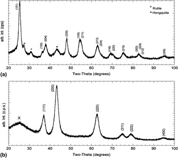
Powder x-ray analysis was performed on both ground foams to classify the titania oxide phases, identify any impurities, and determine the crystallite size by full profile fitting. Figure 1 presents the XRD patterns obtained for TiO2 and TiO samples annealed at a temperature of 950 °C in 6% H2 in N2. In the case of TiO, the major component is identified as cubic TiO with a calculated lattice parameter of 4.1912 (0.0003) Å. The data fit well to PDF #008-0117 with a lattice parameter of 4.177 Å. All six matching peaks are labeled in Fig. 1. All the expected peaks are present with no indication of other phases or impurities. The only feature not explained by a crystalline phase of titanium oxide is a broad peak at about 25°. This extra peak is consistent with an amorphous phase of carbon remaining from the foam formation step. In the case of TiO2, the major component is identified as the tetragonal anatase phase of TiO2 with a calculated lattice parameters of a = b = 3.7880 (0.0003)Å and c = 9.461 (0.002) Å. The data fit well to PDF #021-1272 with a lattice parameters of a = b = 3.7852 Å and c = 9.5139 Å. All the expected peaks are present and labeled in Fig. 1. In this case, there are small amounts of rutile and hongquite phases, which are also labeled in Fig. 1. This material also contains a broad peak consistent with amorphous carbon. The observed carbonaceous material imparts a high degree of conductivity to both samples. In particular, pure TiO2 is not electrically conductive but requires doping of other elements or removal of some of the oxygen atoms to form the more conductive suboxides. Both the TiO2 and TiO materials in this work exhibit the low resistance necessary for use in PEM fuel cells.
XRD patterns from 20 to 100 2 °C for titania samples with (a) TiO2 and (b) TiO.

Further analysis of both patterns and the broad nature of the anatase and titanium oxide peaks are indicative of a very small crystallite size. Full profile fitting of the diffraction data indicates an average crystallite size on the order of 4 nm for TiO and, slightly larger, 8–9 nm for TiO2. By using the polymer-based metal solution, titanium-based foams of varying oxidation states were identified and all materials had crystallite sizes of less than 10 nm based on full profile fitting.
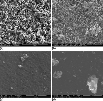
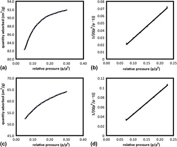
To obtain a more detailed picture of the sample morphology, measurements by SEM and Brunauer-Emmett-Teller (BET) analysis were conducted. The SEM data are shown in Fig. 2 at two levels of magnification (300 and 1 μm) to show the particle distribution and surfaces present in this material. The image in the 300 μm range gives an overview of the material after it was lightly ground into a powder. There is a very large distribution of particle sizes present after the foam formation spanning from approximately 100 μm down into the submicrometer range. Both materials show a similar morphology at this scale consistent with their identical appearance at the macroscopic level. As the magnification is increased, the structure of the surface is revealed as quite complex. At 1 μm magnification, a rough surface is visible within the larger matrix of material. Although identification of individual pores is not possible, the complex surface is not unexpected considering the high surface area of the materials. Surface areas of the as-prepared foams have been measured as high as 280 m2/g; typical surface areas of samples prepared subsequently to these very high surface area samples more typically fall between 150 and 200 m2/g. A representative adsorption isotherm and linear BET plot are presented in Fig. 3 for both samples. The surface area for this sample is 286 and 200 m2/g for TiO and TiO2, respectively. Both samples had a linear correlation coefficient of 0.99 for the BET surface area fit.
SEM images of titania samples annealed at 950 °C for (a) TiO at 300 μm, (b) TiO2 at 300 μm, and (c) TiO at 1 μm and TiO2 at 1 μm.

TiO surface area of 286 m2/g (a) adsorption isotherm and (b) BET linear plot. TiO2 surface area of 200 m2/g (c) adsorption isotherm and (d) BET linear plot.

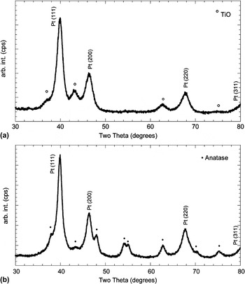
XRD images for titania samples prepared at 950 °C after chloroplatinic acid disposition and reduction at 81 °C for 18–24 h (a) TiO with Pt and (b) TiO2 with Pt.

Following the synthesis and analysis of the conductive supports alone, Pt (20 wt%) was deposited onto each of the titania samples using an incipient wetness approach. Presented in Fig. 4 are the XRD patterns obtained after reduction of the platinum salt at 81 °C for 18–24 h. The pattern of the cubic platinum crystallites is clearly visible within the unchanged anatase and TiO patterns of each sample. The platinum has a larger crystallite size resulting in sharper narrower peaks. Simultaneous full profile fitting of the Pt and TiOX structures in these data indicate an average Pt crystallite size of 50–60 Å for reduction at 81 °C. These small crystallites are advantageous in the effort to maximize efficiency by improving activity without increasing the total amount of platinum required.
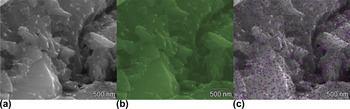
EDX images of TiO samples annealed at 950 °C: (a) total image, (b) titanium, and (c) platinum.

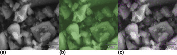
Energy dispersive x-ray analysis (EDX) configured for light element detection was used to look at the distribution of the titanium and to probe the distribution of platinum across the surface of the foam. The EDX images presented in Figs. 5 and 6 show that a uniform distribution of titanium atoms were present within both TiO- and TiO2-based materials. There is also a uniform distribution of carbon content within the titanium oxides, suggesting the possibility of a dependent relationship during the formation of the foam. A very even distribution of platinum particles is also observable in both Figs. 5(c) and 6(c). This image is consistent with the XRD data showing small particles (5 nm crystallites) of Pt distributed across the surface of both materials.
EDX images of TiO2 samples annealed at 950 °C: (a) total image, (b) titanium, and (c) platinum.

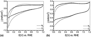
Cyclic voltammetry (at 100 mV/s) of titanium-based supports before Pt addition in deaerated and oxygen saturated 0.5 M H2SO4 solutions (a) TiO and (b) TiO2.

C. Electrochemical characterization
Electrochemical analysis was used to study all the synthesized materials including pre- and postdeposition of platinum onto the TiO2 and TiO foams. Initial characterization used a glassy carbon electrode (0.2475 cm2) deposited with a 1 mg/mL suspension of the as-synthesized titanium oxides after grinding the samples in an alumina mortar with isopropyl alcohol or acetone. Data were collected for both argon- and oxygen-saturated solutions for each sample and are presented in Fig. 7. The TiO does not show any redox couples and only trace ORR activity between 1.2 and 0 V versus RHE. Oxygen is being reduced at lower potentials on the electrode as expected and seen with other supports including carbon at high overpotentials. This process is not related to any chemical reaction of the support with oxygen. Figure 7(b) shows the voltammograms obtained with TiO2. In the measurement conducted in deaerated solution, it is apparent that the support has a redox couple at E 0 = 0.57 V versus RHE. This redox does not seem to be catalytically active when the electrode was exposed to oxygen, and as in the case of TiO, the support is inert for ORR. Both materials show high stability in acidic medium with no changes observed over many cycles and months in an acidic medium. Rotating ring-disk electrode (RRDE) experiment conducted in similar conditions did not show any oxygen reduction activity at relevant potentials as well. These results are supportive of using this material as an unreactive support for platinum-based catalytic activity. The most significant difference between the TiO and TiO2 was a slightly higher capacitance discharge current observed with the TiO2. Although discharge currents are usually observed and expected from high surface area samples, the TiO, which has a higher surface area, shows a lower discharge current, which is due to its inherently higher conductivity versus the TiO2.
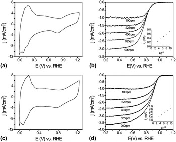
(a) Cyclic voltammetry at 100 mV/s in 0.5 M H2SO4, (b) RDE measurements at 5 mV/s of TiO/Pt in 0.1 M HClO4, (c) cyclic voltammetry at 100 mV/s in 0.5 M H2SO4, and (d) RRDE measurements at 5 mV/s of TiO2/Pt in 0.1 M HClO4.

After thorough analysis of the supports, 20 wt% platinum was deposited onto the surface, and then, they were analyzed using electrochemical methods (24 μg Pt/cm2). Figure 8(a) shows the cyclic voltammogram (CV) of TiO/Pt sample in a deaerated solution. The voltammogram shows hydrogen adsorption/desorption activity similar to Pt loaded on XC-72 carbon.Reference Markovic, Schmidt, Stamenkovic and Ross27 Integration of the area under the cathodic peaks (up to 0.3 V) that are attributed to hydrogen adsorption on the platinum surface yields an electrochemical active surface area (EASA) values of 61.2 and 57.5 m2/gPt for the platinized TiO and TiO2, respectively. These particular values for EASA serve as a reference mark and an upper bound only. These experiments represent our first characterizations of the activities of these materials. In our near-term future work, we will probe these features and examine the stability of the activity seen in these data. In RRDE experiments conducted with 20 wt% Pt on both supports, insignificant amounts (below 1%) of peroxide were detected, indicating a four-electron reduction of oxygen to water. This is supported by the number of electrons calculated from the Levich plots shown in the inset graphs in Figs. 9(b) and 9(d) for TiO/Pt and TiO2/Pt, respectively. The number of electrons involved in the catalysis of ORR is 3.3 for TiO/Pt and 4.0 for TiO2/Pt. The half-wave potential of the reaction measured using RDE in 0.1 M HClO4 are E 1/2 = 0.84 V and E 1/2 = 0.94 V versus RHE for TiO/Pt and TiO2/Pt, respectively. These values are comparable and in the case of TiO2/Pt even higher than Pt on carbon supports.Reference Cai and Adzic28 It is still unclear why the half-wave potential with TiO2/Pt is much higher than that of the TiO/Pt.
IV. CONCLUSIONS
We have successfully synthesized high surface area TiO and TiO2 materials for PEM fuel cell applications. These supports show high conductivity and surface area, both important for catalysts support in fuel cells. After platinum addition at 20 wt% to the both titanium-based supports, electrochemical analysis shows that the platinum is catalyzing oxygen reduction without negligible amounts of peroxide formation and approximately four-electron conversion of oxygen to water. These results are at comparative and slightly higher activity to that published when Pt was deposited on carbon supports such as XC72.
ACKNOWLEDGMENTS
We wish to thank the U.S. Department of Energy Hydrogen Program for providing funding for this work.