Introduction
The significant advancement in unmanned aerial vehicle (UAV) technology allows them to be utilized in a wide range of surveillance and exploration applications such as target detection [Reference Lim, Ryoo, Choi and Cho1], security surveillance [Reference Sabra, Wridan, Alkhatani and Harby2], monitoring health and safety [Reference Kim, Lim, Cho and Côté3], agriculture [Reference Murugan, Garg, Ahmed and Singh4], etc. Therefore, a stringent signal detecting system or communication system should be installed on UAVs to achieve the required applications. A signal detecting system is the backbone of any UAV which provides the capability to transmit high data rates in the broadband spectra [Reference Li and Stoica5]. The signal coverage over larger distances can be achieved by employing broadband antennas. The feature of pattern diversity also enhances the overall coverage [Reference Liu, Weng, Zhang, Qiu, Zhang and Jiao6]. The antenna should be compact in size, thin, and flexible so that it can be easily installed on UAVs without enhancing the overall weight and complexity of UAVs. The traditional and cutting-edge UAV antennas use dipoles and regular-shaped patches, which are incompatible with broadband applications [Reference Sun, Sun, Sun and Huang7, Reference Sharawi, Aloi and Rawashdeh8]. As a result, the objective is to design and develop a broadband antenna that can be conveniently mounted on a UAV. In literature, only a few broadband antennas with thin substrates were found [Reference Michel, Singh and Nepa9–Reference Kumar and Masa-Campos12]. In [Reference Nosrati, Jafargholi and Pazoki13], a slotted blade antenna is presented for broadband UAV applications. In [Reference Lee, Jeoung and Choi14] a cone-based three-dimensional (3D)-printed antenna backed by a tapered cavity structure is presented for wideband and lightweight UAV applications. In [Reference Zong, Ding, Guo and Zhang15] multilayering concept is utilized for enhancing the bandwidth. Three different substrates are utilized to load the driven patch, parasitic patches, and stripline coupled slot on them. In [Reference Mondal and Sarkar16], a volcano smoke antenna was developed for the broadband frequency response. In [Reference Balderas, Reyna, Panduro, Del Rio and Gutiérrez17] a low-profile wideband antenna with a rounded Y shape and a circular parasitic element is designed. Also, there is always a requirement of multiple input, multiple output (MIMO) antennas that provide pattern diversity for the UAV applications without enhancing the overall size of the antenna and overall weight of the UAV [Reference Sufian, Hussain, Askari, Park, Shin and Kim18–Reference Sufian, Hussain, Abbas, Lee, Park and Kim20].
Based on the aforementioned state-of-the-art UAV antennas and the design specifications, in this paper, a thin, low-profile broadband linearly polarized antenna is presented. The antenna can be mounted either on the UAV wings or on flat surfaces without sacrificing performance. Furthermore, the MIMO antenna is designed to provide the antenna with pattern diversity. The proposed antenna provides a broadband frequency range of operation. The evolution of the proposed design is extensively analyzed followed by parametric analysis. The broad bandwidth is achieved by mode coupling which is achieved by introducing a corrugated U-shaped patch along with several parasitic patches. The proposed antenna is excellent to provide aerodynamics to UAVs and reduce aerial vehicle drag in the air. To evaluate the suggested antenna's performance, it is modeled and measured. Thus, the proposed antenna has the advantage of an extremely thin and flexible structure along with broad bandwidth, small size, and acceptable peak gain for establishing an effective communication link between an earth station and UAV, between multiple drones, etc. The rest of the paper is organized as follows: Section “Antenna design and analysis” describes the antenna design configuration and analysis followed by parametric results, Section “Fabrication and measurement” discusses the fabrication and measured results followed by “Conclusion” section in which the paper is concluded.
Antenna design and analysis
Antenna configuration
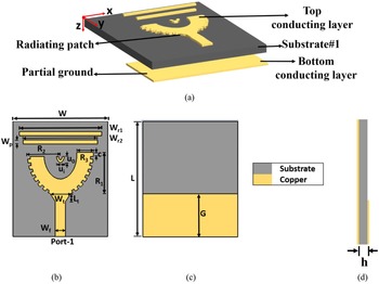
The proposed antenna geometry is shown in Fig. 1. The antenna is designed on a Rogers 5880 substrate with ɛr = 2.2, thickness (h) of 0.782 mm, and loss tangent (tan δ) of 0.002. Figure 1(a) shows exploded view of the proposed antenna. The top view comprising a corrugated U-shaped patch with two parasitic rectangular patches and a central u-shaped patch is shown in Fig. 1(b). The bottom comprising partial ground and side view of the proposed antenna are shown in Figs 1(c) and 1(d), respectively. A better understanding of the design configuration can be obtained by following the design evolution shown in Fig. 2. The design evolution begins with the designing of U-shaped patch fed with a 50 Ω tapered transition microstrip line. The selection of the dimensions of the patch is done based on the guided wavelengths for different frequencies. The guide wavelength is given by [Reference Balanis21]

where the dielectric constant ɛeff is calculated as follows:

where W f and h denote the width of the feedline and thickness of the substrate.
Antenna geometry: (a) exploded view, (b) top view, (c) bottom view, and (d) side view.

Proposed antenna design evolution from narrowband U-shaped antenna to broadband corrugated U-shaped antenna.

The outer major and minor radii of the U-shaped patch are R 1 and R 2 and the inner major and minor radii are R 1–R 3 and R 2–R 3. So the dimensions of the U-shaped patch are chosen such that the total current path satisfies the quarter wavelength concept and the antenna starts radiating at 5.8 GHz. Further, the length of the right arm of the U shape is extended in the Y direction so that a few other modes are also excited (antenna I). Two parasitic rectangular patches are added in addition for the broadening of bandwidth (antenna II). The dimensions of the parasitic rectangular patches are chosen such that the most nearby mode at 5.25 GHz is excited. For the further broadening of the bandwidth, an extra u-patch is introduced inside the main U-shaped patch (antenna III). The central u-shaped patch and the two parasitic rectangular patches serve the purpose of broadening the bandwidth as well as retaining the size compactness of the antenna.
Finally, for obtaining a broadband antenna corrugations are introduced in antenna III so that the total current path gets enhanced leading to further enhancement of bandwidth (proposed antenna IV). The final antenna structure is optimized using the Computer Simulation Technology (CST 2020) full wave simulation software. The values of the dimensional parameters of the optimized antenna are illustrated in Table 1. A comparison between the S 11 of antenna I, antenna II, antenna III, and the proposed antenna is shown in Fig. 3. It can be observed that the parasitic rectangular patches and the central u-shaped patch enhance the bandwidth from 10 to 20%. The final proposed antenna exhibits a broad bandwidth of 66.6% from 4.5 to 9.0 GHz.
Comparison between the S 11 of antennas I, II, III, and IV.

Antenna dimensional parameters

Surface current distribution
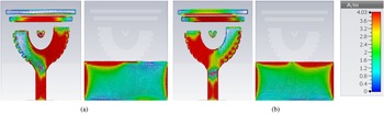
The current distributions at the two frequencies 5.45 and 6.2 GHz are shown in Figs 4(a) and 4(b) for both top and bottom of the antenna, respectively. It can be observed that by introducing the parasitic patches the overall current path increases thus resulting in lower resonances and actual size reduction. As shown in Fig. 4(a), the lower resonance is mainly governed by the right arm of the corrugated U-shaped patch, the central u-shaped parasitic patch and the two rectangular parasitic patches. Similarly, as shown in Fig. 4(b), the higher resonance is mainly governed by the left arm of the corrugated U-shaped patch and the two rectangular parasitic patches. However, the upper parasitic rectangular patch and the partial ground are mainly contributing toward the impedance matching in the entire band.
Surface current distribution at (a) 5.45 GHz and (b) 6.20 GHz.

Parametric study
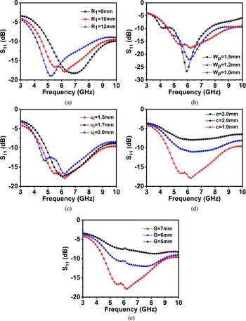
To further understand the design of the proposed broadband antenna parametric studies are carried out. The major parameters that affect the frequency, bandwidth, and reflection coefficient are: outer radius of the U-shaped patch (“R 1”), width of the parasitic rectangular strip patches (“Wp”), radius of the parasitic u-shaped patch (“ui”), width of the corrugations (“c”), and the partial ground (“G”). Figures 5(a)–5(e) show the variation in the reflection coefficient of the proposed antenna on varying different parameters. As the outer radius of the U-shaped patch serves an important role in deciding the main working frequency, therefore a variation in R 1 from 8 to 12 mm shifts the resonance frequency toward the lower frequency regime (Fig. 5(a)). Based on the desired frequency of operation the most optimum value of R 1 is considered as 10 mm. Further, the width (Wp) of the parasitic rectangular strip patches is varied to observe a change in the bandwidth of the antenna. Figure 5(b) illustrates that as the width changes from 1.5 to 1.0 mm, the corresponding resonance frequency changes from 4.12 to 5.45 GHz. However, no significant change is observed in the resonance at 5.8 GHz. It is because the resonance at 5.8 GHz is governed by the main U-shaped patch. So, based on the results the most optimum width of the rectangular parasitic strip patch is 1.0 mm because it exhibits the widest bandwidth. Similar effect is observed by varying the radius (ui) of the central parasitic u-shaped patch (Fig. 5(c)). As the radius of the patch increases from 1.5 to 2.5 mm the resonance changes from 5.8 to 4.6 GHz. The most important factor governing the bandwidth and the S 11 of the proposed antenna is the width of the corrugations “c”. Figure 5(d) illustrates the variation in width of corrugations affecting the bandwidth and S 11. As the width increases from 1.0 to 2.0 mm the impedance matching gets affected and the S 11 shifts upward thereby decreasing the overall bandwidth of the antenna. Thus c = 1.0 mm is considered as the most optimum value for obtaining the broad bandwidth. The effect of variation in the length of the metallic ground (“G”) is illustrated in Fig. 5(e). The variation in the length affects the impedance matching of the antenna. As the length of ground increases from 5.0 to 7.0 mm the impedance matching improves. On further increasing the length of the ground beyond 7.0 mm, the impedance matching will improve further but the desirable bandwidth will be reduced correspondingly. Therefore, the most optimum length of ground is considered as 7.0 mm.
Effect of variation of design parameters of the proposed antenna: (a) major radius “R 1” of the corrugated U-shaped patch, (b) width of the parasitic rectangular patches “Wp,” (c) radius of the inner u-shaped patch “ui,” (d) width of corrugations “c,” and (e) effect of partial ground “G.”

Performance analysis of 2 × 2 quad-port MIMO antenna
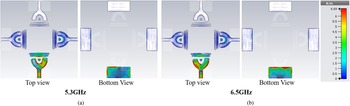
A four-element MIMO configuration, employing the proposed antenna in a 2 × 2 matrix form, is shown in Fig. 6. The antenna elements are arranged orthogonally on the center of four edges of a square substrate with a side dimension of 79 mm. The minimum spacing (“s”) between the two facing antenna elements (antennas 1 and 3) and (antennas 2 and 4) to exhibit acceptable isolation is 28 mm. The surface current distribution of the 2 × 2 MIMO antenna is illustrated in Figs 7(a) and 7(b) at 5.3 and 6.5 GHz, respectively. A good level of isolation between the adjacent antenna elements is observed. Also similar to the current distribution of the single-element antenna, the right arm of corrugated U-shaped patch is mainly governing the lower resonance while the left arm is mainly governing the higher resonance.
Layout of 2 × 2 quad-element MIMO antenna: (a) top view and (b) bottom view.

Surface current distribution of the quad-port MIMO configuration at (a) 5.3 GHz and (b) 6.5 GHz.

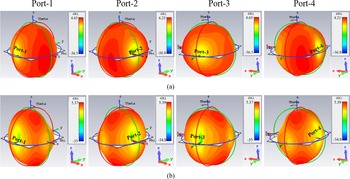
The 3D radiation pattern of the 2 × 2 quad-port MIMO antenna at 5.3 and 6.5 GHz is shown in Figs 8(a) and 8(b), respectively. An omnidirectional radiation is observed at both the frequencies. The broadside radiation exhibited on exciting the two transverse ports (port-1, 3 and port-2, 4) is almost identical. However, the orthogonal ports (port-1, 2, port-2, 3, port-3, 4, port-4, 1) offer orthogonal polarization of the radiation pattern at both frequencies.
Simulated 3D radiation pattern of the 2 × 2 quad-port MIMO antenna.

Fabrication and measurement
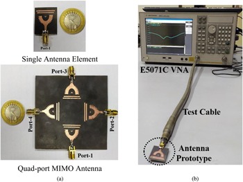
A fabricated prototype of the broadband single-element antenna and the MIMO configuration is portrayed in Fig. 9(a). After fabrication, the prototypes are tested using the Vector Network Analyzer E5071C (Fig. 9(b)). The simulated and measured S-parameters of both the prototypes are depicted in Fig. 9.
(a) Photograph of the fabricated single-element antenna and quad-port MIMO antenna, and (b) S 11 measurement setup of single-element antenna.

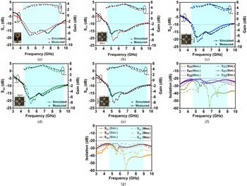
A good agreement between the measured and simulated results is observed. The measured values of S 11 of the single-element antenna illustrated in Fig. 10(a) show a consistent −10 dB bandwidth ranging from 4.1 to 9.0 GHz (74.8%). Almost similar bandwidth is exhibited by all four ports of the MIMO configuration as depicted in Figs 10(b)–10(e). Also, fairly good isolation, i.e. >20 dB for the entire bandwidth between the adjacent antenna elements is observed in Figs 10(f) and 10(g). As the antenna elements are identical and the spacing between them is also identical, therefore the level of isolation between the adjacent antennas elements is also almost identical.
Comparison between the simulated and measured results: (a) S 11 of single-element antenna, (b) S 11 of quad-port MIMO antenna, (c) S 22, (d) S 33, (e) S 44, and (f), (g) isolation between adjacent ports.

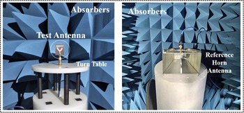
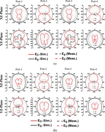
The radiation performance of the antenna is measured at the far-field distance in the anechoic chamber. The distance between the reference antenna (horn) and the antenna under test is maintained greater than 2D 2/λ. Figure 11 shows the far-field measurement setup of the single-element antenna in the anechoic chamber. The normalized radiation characteristics of the individual antenna in the MIMO antenna at 5.3 and 6.5 GHz in both E and H planes are shown in Figs 12(a) and 12(b), respectively. Omnidirectional radiation is observed at both frequencies. The level of cross-polarization is low in the orthogonal plane as compared to the cross-polarization in the same plane. The orthogonal polarization of the radiation pattern at both frequencies also confirms the orthogonal arrangement of the four antenna elements in the MIMO configuration. The broadside radiation at 180° shows that the maximum antenna radiation is exhibited in the direction below the drone structure. This characteristic makes the antenna the most suitable choice for establishing effective communication with the users on the ground. However, the radiation characteristics of the antenna make it a good choice for establishing communication above the earth also. The simulated and measured results for the peak gain of the broadband single-element antenna and the MIMO antenna are depicted in Figs 10(a)–10(e). The values of the peak gain of single element and of MIMO configuration are greater than 3.0 and 3.8 dB, respectively for the entire bandwidth. However, the maximum measured peak gain of 5.02 dBi is observed at 6.6 GHz for MIMO antenna.
Far-field pattern measurement setup of the proposed antenna.

Comparison between the simulated and measured radiation pattern at (a) 5.3 GHz and (b) 6.5 GHz.

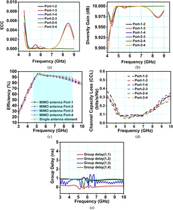
The essential performance parameters such as error correlation coefficient (ECC) and diversity gain (DG) were analyzed using the measured S-parameters to verify the high performance of the proposed quad-port MIMO antenna. The ECC and DG are calculated using the following relations [Reference Khalid, Awan, Hussain, Fatima, Ali, Hussain, Khan, Alibakhshikenari and Limiti22, Reference Zahra, Awan, Ali, Hussain, Abbas and Mukhopadhyay23]:


The ECC measures the self-governing performance of individual antenna element utilized in the MIMO configuration as compared to other antenna elements. In ideal case the ECC should be 0, however, practically the ECC values below 0.5 are acceptable. The ECC between all four adjacent ports and collinear ports of the 2 × 2 quad-port MIMO antenna is plotted for the entire frequency range. Figure 13(a) depicts that the ECC values between all the ports are well below 0.01. Also, it can be observed that the ECC between the collinear ports is very small as compared to the ECC between the adjacent ports. The reason behind this may be due to the larger separation distance between the collinear ports and the smaller separation distance between the adjacent ports. Thus, the smaller values of ECC depict the strong isolation between the individual antenna elements in the quad-port MIMO antenna. The DG of the MIMO configuration is shown in Fig. 13(b). It can be observed that as the ECC values are very small, therefore the DG is also almost constant and around 10 dB. Figure 13(c) depicts the simulated efficiency of the single-element antenna and the MIMO antenna. The efficiency of the single-element antenna is greater than 88% for the entire bandwidth. However, the efficiency of the MIMO configuration is greater than 82% for the entire bandwidth. At 5.3 GHz the efficiency of the MIMO configuration is 95.3% and at 6.5 GHz the efficiency is 92.1%. The channel capacity loss (CCL) is also calculated to measure the correlation between multiple ports of the quad port MIMO antenna. It also signifies the quality of data transmission over the entire bandwidth. The value of CCL is determined by utilizing the following equations [Reference Hussain, Awan, Ali, Naqvi, Zaidi and Le24]:

where the correlation matrix ρc of the antenna is expressed as:


Performance evaluation of the MIMO antenna: (a) calculated envelope correlation coefficient and (b) calculated DG of the proposed quad-port MIMO antenna, (c) simulated efficiency, (d) CCL, and (e) group delay at port-1.

The acceptable value of CCL extends up to 0.5 bits/s/Hz. The CCL values below 0.5 bits/s/Hz signify high data transfer rate. The CCL values of the proposed MIMO antenna between the adjacent ports and the transverse ports are depicted in Fig. 13(d). It can be observed that the CCL values are below 0.38 bits/s/Hz for the entire bandwidth. However, at 5.3 GHz the value of CCL is minimum i.e. 0.05 bits/s/Hz.
Group delay is determined to obtain the information about the temporal delay between the envelopes of the amplitude of various sinusoidal components of a signal on passing them through a test device. Each component's function depends on frequency, therefore even when the envelope is delayed, the shape will remain the same as the original. Group delay describes the gap in time between the input burst's envelope and the output burst's amplitude envelope. The group delay characteristics of port-1 of the 2 × 2 quad-port MIMO antenna are shown in Fig. 13(e). The delay from port-1 to port-1 is illustrated by group delay (1,1) and the delay from port-1 to port-2 is illustrated by group delay (1,2). Since the antenna elements at port-2 and port-4 are identical therefore the group delay (1,4) is almost similar to group delay (1,2). The delay from port-1 to port-3 is shown by group delay (1,3). The whole group delay of the proposed quad-port MIMO antenna is less than 1.6 ns.
Table 2 illustrates the assessment of the proposed broadband antenna performance with other newly published works in terms of size, bandwidth, number of bands, gain, and antenna geometry. It is observed that the proposed antenna transcends the low profile, wide bandwidth, and size compactness specification in comparison to other broadband UAV antennas. Also, the proposed antenna offers the feature of pattern diversity with a good amount of isolation between the individual ports. In addition, the size of the array antenna is also low profile as compared to other pattern diversity antennas.
Comparative performance analysis of the proposed antenna with other drone antennas

Conclusion
A thin, compact, and broadband antenna is designed, fabricated, and tested for airborne UAV-based applications in the C-band. The U-shaped patch, few parasitic patches, and the partial ground contribute to enhancing the overall impedance bandwidth of the antenna. The overall bandwidth of 74.5% (4.1–9.0 GHz) is exhibited by the antenna. Since the antenna is designed on a thin substrate of 0.01λ 0 thickness, it can be mounted on the drone body without enhancing the overall weight of the drone. The pattern diversity is provided by the orthogonally placed quad-port 2 × 2 MIMO configuration of the antenna. The level of isolation between the adjacent ports is also greater than 20 dB for the entire bandwidth. The proposed antenna exhibits a stable omnidirectional radiation pattern that satisfy the major prerequisites of an antenna for UAV applications.
Conflict of interest
The authors declare no potential conflicts of interest.
 Kapil Jain received his B.E. degree in electronics and communication in 2004, and his M.E. degree in power electronics in 2011 from RGPV University, Bhopal. He is currently a research scholar in Amity University, Gwalior. His research areas include designing of microstrip patch antennas for 5G applications.
 Dr. Vivek Singh Kushwah received his B.E. degree from Rajiv Gandhi Technical University, India in 2005, M.Tech. degree from the Madhav Institute of Technology and Science, Rajiv Gandhi Technical University, India in 2007, and Ph.D. degree in electronics engineering from the Madhav Institute of Technology and Science, Rajiv Gandhi Technical University, India in 2016, respectively. He is currently working as a professor in Electronics and Communication Engineering Department, Amity University, Gwalior. He has more than 14 years of teaching experience in academics. His areas of interests include artificial neural networks, microstrip antenna, RF and microwave filters. He is associated with many IEEE international conferences around the world as a conference committee member. He is also editor of many international journals such as International Journal of Communication Systems and Network. He is member of many professional bodies such as Senior Member IEEE, Fellow IETE and IET, and so on.