1. Introduction
Autonomous navigation systems have advanced significantly, establishing simultaneous localization and mapping (SLAM) as a fundamental technology. This progress underscores SLAM’s crucial role in robotics and intelligent vehicles [Reference Marshall, Sun and L’Afflitto1, Reference Xu, Zhang, Yang, Cao, Wang, Ran, Tan and Luo2]. While traditional LiDAR-based SLAM (e.g., Google Cartographer [Reference Hess, Kohler, Rapp and Andor3]) achieves millimeter-level geometric accuracy through precise point cloud registration, it fundamentally lacks semantic awareness – a critical limitation in dynamic environments where moving objects (pedestrians, vehicles) frequently invalidate the static world assumptions [Reference Fang and Li4]. Conversely, the visual SLAM systems leverage rich texture information for semantic interpretation [Reference Barros, Michel, Moline, Corre and Carrel5], yet remain vulnerable to photometric disturbances (illumination variations, shadows) and dynamic interference, which often leads to catastrophic tracking failures in crowded scenes [Reference Kenye and Kala6].
This dichotomy highlights three persistent challenges: (1) geometric-semantic disparity – LiDAR and visual modalities exhibit complementary strengths but lack unified representation for dynamic object reasoning. While recent methods like SLAM2 [Reference Lin, Zhang, Tian, Yu, Ye, Zhuang and Lan7] advance multi-mode mapping in dynamic scenes, the challenge of creating a unified map by actively eliminating dynamic features across modalities remains. (2) Sensor degradation – LiDAR suffers from sparse feature distribution in structurally repetitive environments (e.g., long corridors), while cameras fail under extreme lighting. Although systems like LIVS [Reference Cheng, Li, Li, Wang, Li and Wang8] effectively mitigate geometric degradation through tight coupling, robust visual feature extraction under severe photometric disturbances (e.g., uneven illumination) requires dedicated enhancement. (3) Fusion uncertainty – existing multi-sensor SLAM frameworks [Reference Lai9] typically employ heuristic fusion rules, neglecting the probabilistic nature of heterogeneous sensor noise profiles.
Early approaches to dynamic environments relied primarily on geometric consistency checks. For instance, Eslamian et al. [Reference Eslamian and Ahmadzadeh10] introduced a detection-aided visual SLAM framework using modern deep learning detectors (Detectron2). This approach improved robustness in highly dynamic scenes. However, such methods exhibited high false-negative rates in low-texture regions. They also struggled with temporarily static objects. More recent semantic-aware solutions have further improved dynamic understanding. Ma et al. [Reference Ma, Jiang, Ou and Xu11] proposed a semantic-geometric fusion approach for multi-object tracking and LiDAR odometry. This method enhanced performance in dynamic settings. Bescos et al. [Reference Bescos, Fácil, Civera and Neira12] employed semantic segmentation in DynaSLAM to filter dynamic features, significantly improving the positioning accuracy. Despite the effectiveness, these methods often incur high computational costs. They depend heavily on GPU inference, which limits the real-time applications. To balance accuracy and efficiency, hybrid frameworks have emerged as a solution. Zhang et al. [Reference Zhang, Dong and Guo13] combined the improved Mask R-CNN modules with geometric cues. This approach achieved more reliable dynamic object handling while mitigating partial occlusion and segmentation errors.
Recent research has increasingly turned to multi-sensor fusion in order to overcome the limitations of individual sensing modalities. For instance, MSF-SLAM [Reference Lv, He, Yang, Nie, Dong, Wang and Gao14] presented a fusion-based framework that combined camera and LiDAR data at the front end and incorporated visual-LiDAR loop closure to achieve robust localization and mapping in complex dynamic environments. A comprehensive review by Chen et al. [Reference Chen, Zhao, Zeng, Liu, Liu, Sun, Li, Chen, Liu and Qiao15] further summarized the recent advances in LiDAR-visual fusion techniques, highlighting the emerging trends and methodologies. Despite these advances, many current systems still operate under predominantly static assumptions and exhibit limited performance in crowded scenarios. Furthermore, they often prioritize localization accuracy while overlooking structured map fusion for navigation tasks. In terms of learning enhancement, semantic segmentation methods like FCN [Reference Long, Shelhamer and Darrell16] and SegNet [Reference Badrinarayanan, Kendall and Cipolla17] leverage large-scale learned priors to improve contextual awareness and robustness. However, these methods often entail substantial computational costs and require extensive training data, making them less suitable for resource-constrained platforms. In contrast, lightweight detection solutions such as YOLOv7 [Reference Wang, Bochkovskiy and Liao18] emphasize efficiency through optimized architectures and real-time processing capabilities. Yet, these approaches remain susceptible to visual degradation issues, including motion blur and illumination changes, particularly in demanding visual environments.
Map integration remains challenging due to heterogeneous sensor representations. Recent surveys and advances in collaborative SLAM [Reference Sunil, Mozaffari, Singh, Shahrrava and Alirezaee19, Reference Yu, Fu, Gostar and Hu20] have developed feature-based occupancy map merging techniques and reviewed map-merging methods for multi-robot systems. However, most current approaches still assume static environments and lack effective mechanisms to resolve sensor conflicts in dynamic scenarios.
The proposed DynaFusionSLAM framework systematically addresses the three core challenges. (1) It bridges the geometric-semantic disparity by combining deep learning with multi-view geometry to eliminate dynamic features. (2) It mitigates sensor degradation by employing adaptive image enhancement and quadtree-based homogenization for robust feature extraction. (3) It addresses the fusion uncertainty through a corridor-optimized architecture that employs an improved Harris corner detection algorithm and Bayesian fusion. The system is validated on six TUM RGB-D dynamic sequences, demonstrating superior dynamic feature elimination. Large-scale simulations in complex corridor topologies (U-/T-/Z-shaped) confirm structural fidelity preservation in fused maps, and real-world mapping experiments in dynamic corridors validate the multi-modal fusion framework through rigorous spatiotemporal consistency.
2. Methodology
The SLAM framework proposed in this paper, which integrates LiDAR and depth cameras through task-level fusion, is architecturally depicted in Figure 1.
Framework of DynaFusionSLAM.

2.1. Dynamic object elimination
Instance segmentation is performed using Mask R-CNN [Reference He, Gkioxari, Dollár and Girshick21] to identify dynamic objects and filters their feature points. The model is implemented with the Detectron2 framework (PyTorch 1.13.0, CUDA 11.7) and uses the COCO pre-trained weights (R50-FPN backbone) without fine-tuning to maintain generalizability. Figure 2 illustrates dynamic feature detection results of a COCO-pretrained model evaluated on a TUM dataset sample:
Dynamic mask based on prior model.

As shown in Figure 2(c), parts of the person’s body are still exposed outside the mask, which may lead to incomplete removal of dynamic points. Therefore, this paper performs a "dilation" operation on the original mask. The dilated result in Figure 2(d) fully encapsulates the person’s contour within the mask, eliminating erroneous extraction of partial dynamic object features caused by incomplete mask coverage. This can improve the system’s accuracy.
Dynamic feature detection based on multi-view geometry.

This paper employs multi-view geometry to further determine potentially mobile objects that either lack prior models or exhibit low motion probability in existing prior models, thereby achieving enhanced dynamic object elimination performance. The multi-view geometry algorithm follows this workflow:
-
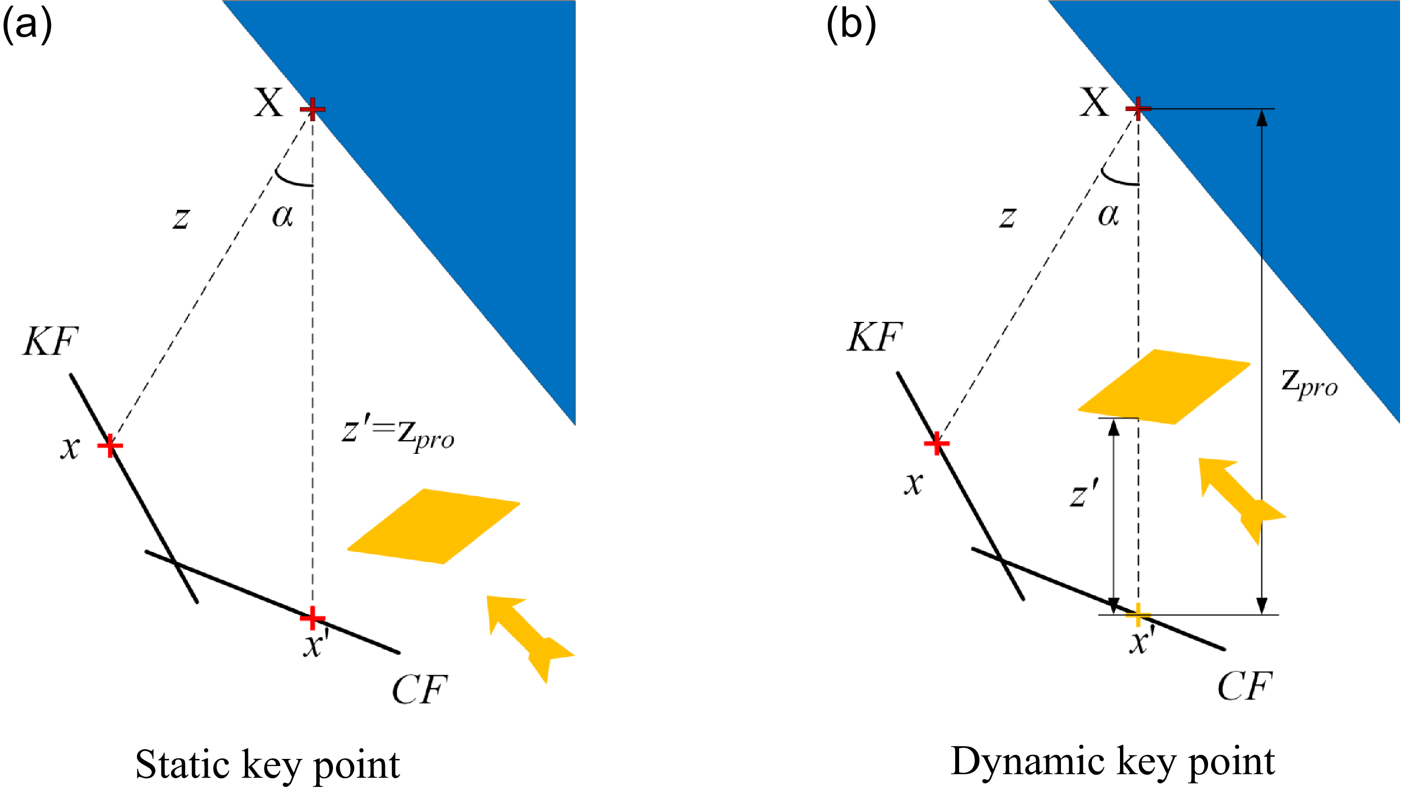
1. Select a subset of images with the greatest overlap with the current frame (CF) as key frames (KF), and set the number of key frames.
-
2. Project each feature point
 $x$
from the previous KF onto the CF, denoted as
$x'$
, and calculate their projected depth
$z_{pro}$
, as shown in Figure 3.
-
3. For each feature point, use its corresponding 3D coordinate
$X$
to calculate the parallax angle
$\alpha$
between points
$x , x'$
, and
$X$
, and set the threshold
$\tau _{\alpha }$
. -
4. Based on the depth map obtained from the RGB-D camera for the current frame, the depth value
$z'$
corresponding to point
$x'$
is obtained. The difference between the projected depth and the real depth,
$\bigtriangleup z=z_{pro}-z'$
, is calculated, and a threshold
$\tau _{z}$
is set. -
5. Determine whether the point is a dynamic feature point. If the difference between the projected depth and the real depth is small, i.e.,
$\bigtriangleup z=0\ll \tau _{z}$
and the disparity angle
$\alpha \lt \tau _{\alpha }$
, the point is considered static, as shown in Figure 3(a). Otherwise, it is classified as a dynamic keypoint, as shown in Figure 3(b). -
6. The thresholds for the multi-view geometry check, specifically the parallax angle
$\tau _{\alpha }=15^{\circ}$
and the depth difference
$\tau _{z}=0.5m$
, were determined through a grid search on the TUM RGB-D datasets to maximize the F1-score for dynamic point detection. A parallax angle exceeding
$15^{\circ}$
indicates significant motion inconsistency, while a depth difference larger than
$\tau _{z}=0.5m$
substantially surpasses the typical depth noise (e.g., < 4 cm for RGB-D cameras like Intel RealSense D435) of the sensor. These two criteria provide strong evidence for the identification of a dynamic point. These values have been validated across multiple sequences and proved effective in distinguishing true motion from sensor noise.


Thus, the dynamic object elimination strategy presented in this section operates through a dual-stage pipeline to ensure comprehensive filtering. In the first stage, a pre-trained Mask R-CNN model is employed to perform instance segmentation and mask a priori known dynamic objects (e.g., pedestrians), which effectively removes the large-scale dynamic interferences based on semantic priors. However, this semantic approach alone is insufficient to handle objects lacking pre-defined models or those that may still exhibit movement despite having low motion probability in the prior knowledge base. To mitigate this limitation, the second stage incorporates a multi-view geometry constraint. Consequently, this synergistic combination ensures the robust elimination of both macroscopic dynamic entities and finer-grained dynamic feature points, thereby substantially enhancing the system’s resilience in complex dynamic environments.
Image enhancement flow chart.

2.2. Improved ORB feature extraction
The ORB-SLAM2 system utilizes ORB feature extraction in its visual odometry module for efficient computation. However, its fixed thresholds restrict the adaptability to illumination changes, while texture-dependent feature extraction results in uneven feature distribution – specifically, feature clustering in texture-rich areas vs. sparse features in texture-poor regions – thereby degrading the accuracy of pose estimation. Our solution proposes two key improvements: (1) adaptive gamma correction (AGC) for illumination-robust image enhancement and (2) an optimized quadtree algorithm designed to ensure uniform feature distribution. These two components significantly enhance the robustness and localization accuracy of the ORB algorithm.
The adopted image enhancement algorithm follows the workflow illustrated in Figure 4. The RGB image is first converted to grayscale, with each pixel intensity denoted as
 $I(x,y)$
. The standard deviation of the grayscale values is computed as:
 \begin{equation} \lambda =\sqrt{\frac{1}{M\cdot N}\sum _{x=1}^{M}\sum _{y=1}^{N}\left(I(x,y)-\overline{I}\right)^{2}} \end{equation}
where
 $\overline{I}$
is the mean intensity. If
 $\lambda \lt 0.25$
, the image is considered to have sufficient quality. Otherwise, it undergoes further processing. If
 $\overline{I}\lt 128$
, the image is deemed under-exposed and enhanced via AGC; otherwise, it is inverted before AGC.
AGC automates gamma adjustment using image statistics to improve contrast across varying illumination. The probability density of grayscale level
 $i$
is:
 \begin{equation} P(i)=\frac{n_{i}}{M\cdot N} \end{equation}
where
 $n_{i}$
is the number of pixels at level
 $i$
. A weighted probability density is then derived:
 \begin{equation} P_{\omega }(i)=P_{\max }\cdot \left(\frac{P(i)-P_{\min }}{P_{\max }-P_{\min }}\right)^{\alpha } \end{equation}
Here,
 $P_{\max }$
and
 $P_{\min }$
are the maximum and minimum probability densities, and
 $\alpha =0.2$
is a smoothing factor. The weighted distribution function is:
 \begin{equation} C_{\omega }(i)=\sum _{i=0}^{255}\frac{P_{\omega }(i)}{\sum P_{\omega }} \end{equation}
The gamma parameter is adapted as
 $\gamma =1-C_{\omega }(i)$
, and the corrected intensity is:
 \begin{equation} I'(x,y)=255\!\cdot\! \left(\frac{I(x,y)}{255}\right)^{\gamma } \end{equation}
To resolve the uneven feature distribution caused by varying image textures, this study enhances the camera pose estimation accuracy by implementing an improved quadtree algorithm that prevents redundant feature clustering and achieves feature homogenization. Traditional quadtree algorithms lack constraints on node splitting depth during homogenization. Excessive splitting leads to increased memory consumption and computational complexity, thereby reducing computational efficiency.
Our method introduces a constraint on the maximum node splitting depth to curb computational costs. Building upon the mathematical properties of the quadtree, where each splitting level increases the number of potential nodes by a power of four, we establish a theoretical relationship between target feature quantity
 $n_{\max }$
and maximum depth
 $d_{\max }$
. This relationship is analytically formulated as:
 \begin{equation}d_{max}=[\!\log _{4} n_{max}]\end{equation}
In the above equation,
 $n_{\max }$
represents the number of feature points to extract, and
 $d_{\max }$
is the split depth threshold. This conditional check is incorporated into the original node splitting step to verify whether the current splitting depth
 $d$
is less than the predefined maximum depth threshold
 $d_{\max }$
. Nodes are permitted to undergo further splitting only when
 $d\lt d_{\max }$
, thereby preventing excessive subdivision and ensuring computational efficiency.
In the improved ORB feature extraction process of this section, image preprocessing and feature extraction are carried out sequentially. First, AGC is applied to the RGB images acquired from the Intel RealSense D435 camera to enhance image quality by mitigating uneven illumination and improving contrast. Subsequently, the enhanced images are processed with the improved quadtree algorithm to achieve a more uniform spatial distribution of ORB feature points. This sequential processing pipeline ensures both improved image quality and reliable feature distribution.
2.3. Map fusion
The two key steps in map fusion are map alignment and information fusion [Reference Bosse and Zlot22]. The goal of map alignment is to ensure that both maps have the same format, scale, and resolution. Alignment algorithms [Reference Li, Wang and Kaess23, Reference Huang, Scherer and Kaess24] compute coordinate transformations between submaps, establishing the foundation for subsequent information association. Information association, after map alignment, is the process of merging information between maps to generate the final scene map. Figure 5 illustrates the complete fusion process.
Map fusion flow chart.

In the map alignment phase, this paper proposes a combined alignment algorithm tailored for corridor environments. In Harris corner detection, corner responses change with map resolution, which may cause original corners to become unrecognizable. To address this, we incorporate scale invariance into the Harris corner detector.
First, the first-order image derivatives at point
 $(x,y)$
using the differential scale
 $\sigma _{D}$
are defined as:
 \begin{align} I_{x}(x,y,\sigma _{D})&=\frac{\partial }{\partial x}\left[g(\sigma _{D})\otimes I(x,y)\right]\\[-10pt]\nonumber \end{align}
 \begin{align} I_{y}(x,y,\sigma _{D})&=\frac{\partial }{\partial y}\left[g(\sigma _{D})\otimes I(x,y)\right] \end{align}
where
 $g(\sigma _{D})$
is a Gaussian kernel with standard deviation
 $\sigma _{D} , \otimes$
denotes the convolution operation, and
 $I(x,y)$
is the original image.
Next, the structure tensor composed of quadratic terms of the image derivatives is constructed:
 \begin{equation} S(x,y,\sigma _{D})=\left[\begin{array}{ll} I_{x}^{2}(x,y,\sigma _{D}) & I_{x}I_{y}(x,y,\sigma _{D})\\[5pt] I_{x}I_{y}(x,y,\sigma _{D}) & I_{x}^{2}(x,y,\sigma _{D}) \end{array}\right] \end{equation}
Finally, the scale-invariant Harris second-moment matrix is obtained by convolving the structure tensor
 $S$
with a Gaussian kernel
 $g(\sigma _{I})$
of standard deviation
 $\sigma _{I}$
, which yields:
 \begin{align} M(x,y,\sigma _{D},\sigma _{I})&=\sigma _{D}^{2}\cdot \left[g\left(\sigma _{I}\right)\otimes S(x,y,\sigma _{D})\right]\nonumber\\[5pt] &=\sigma _{D}^{2}\left[\begin{array}{ll} g\left(\sigma _{I}\right)\otimes I_{x}^{2}(x,y,\sigma _{D}) & g\left(\sigma _{I}\right)\otimes I_{x}I_{y}(x,y,\sigma _{D})\\[5pt] g\left(\sigma _{I}\right)\otimes I_{x}I_{y}(x,y,\sigma _{D}) & g\left(\sigma _{I}\right)\otimes I_{y}^{2}(x,y,\sigma _{D}) \end{array}\right] \end{align}
where
 $\sigma _{D}$
is the differential scale window, and
 $\sigma _{I}$
is the integral scale window. The differential scale window determines the variation of the differential values around the corner, filtering out noise around the corner through Gaussian smoothing. The integral scale window defines the current scale of the corner, which corresponds to the size of the filtering window
 $(x,y)$
.
The framework first constructs a multi-scale space
 $\sigma _{n}=\sigma _{I},k\sigma _{I},\ldots ,k^{n}\sigma _{I}$
. At each scale, it calculates the corner response value and applies non-maximum suppression within the 8-neighborhood of candidate corner points exceeding the predefined threshold. Subsequently, the algorithm computes the Laplacian of Gaussian (LoG) response at candidate corner positions across all scales:
 \begin{equation} \left| LoG\!\left(x,\sigma _{n}\right)\right| =\sigma _{n}^{2}\left| I_{xy}\left(x,\sigma _{n}\right)+I_{yy}\left(x,\sigma _{n}\right)\right| \end{equation}
Compare the
 $LoG$
values [Reference Mikolajczyk and Schmid25] in adjacent scale spaces:
 \begin{equation} \left| LoG\!\left(x,\sigma _{n}\right)\right| \gt \left| LoG\!\left(x,\sigma _{i}\right)\right| ,\forall \sigma _{i}\in \left\{\sigma _{n-1},\sigma _{n+1}\right\} \end{equation}
When Eq. (12) holds, the candidate corner point remains valid until the algorithm identifies the maximum
 $LoG$
value at its position across multiple scales. This maximum
 $LoG$
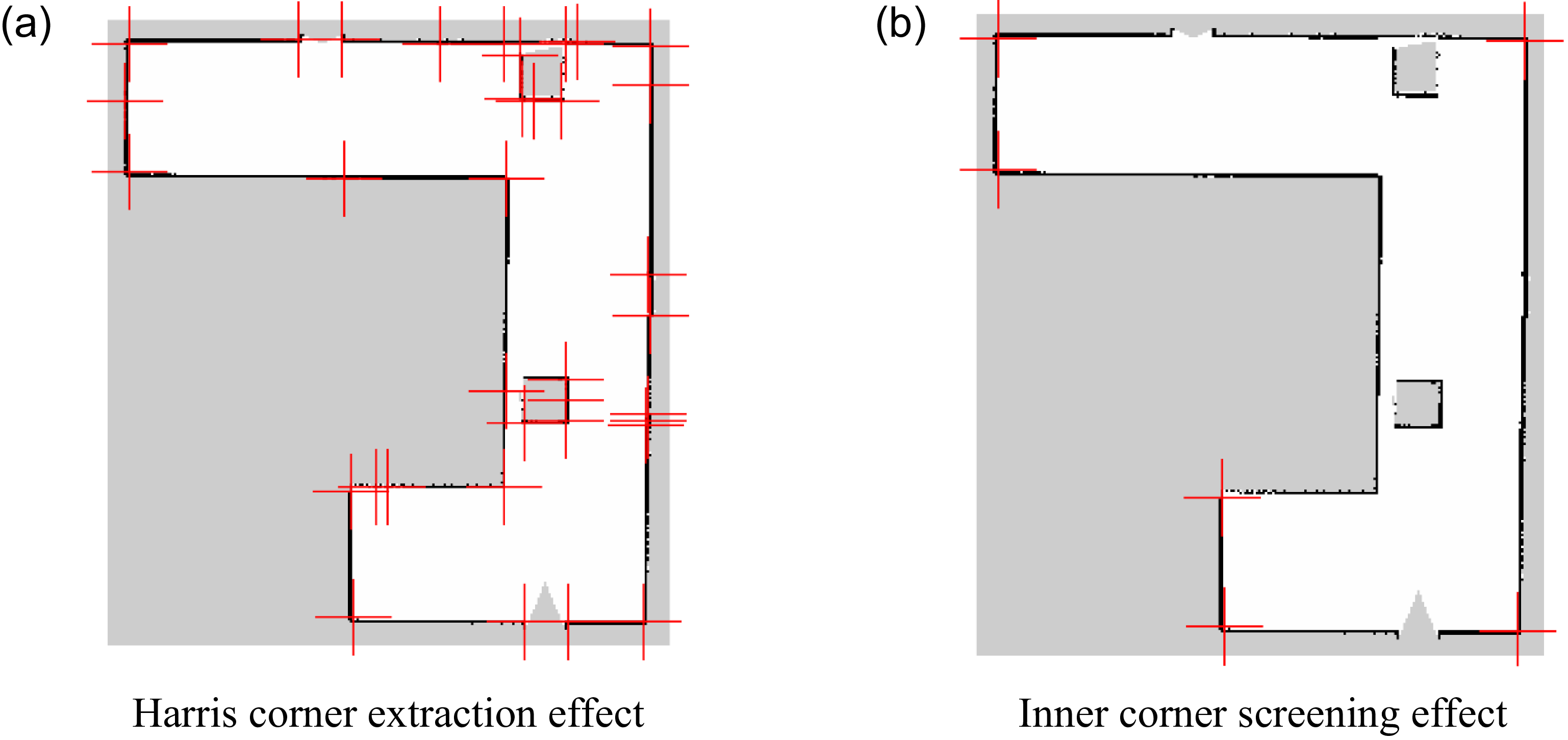
value determines the optimal scale for the corner point. Following Harris corner detection, a similarity-based filtering mechanism is applied to remove redundant corner points. In corridor environments, wall junctions exhibiting distinct geometric features are regarded as inner corner points, selected based on the occupancy ratio of grid states within a radius
 $r$
. Figure 6 illustrates the screening results after applying these criteria. The red crosses in the figure represent the positions of the Harris corner points. As seen in Figure 6(a), the original detected corner points contain redundancy. Figure 6(b) demonstrates the filtered results containing internal corner points, where only wall-corner keypoints remain after screening. Subsequently, the centroid method assigns a dominant orientation to internal corner points to ensure rotational invariance.
From redundant Harris corner detection to interior corner extraction results.

To endow the Harris corner with a rotational descriptor, this paper employs an improved BRIEF feature as the inner corner descriptor. The improved BRIEF descriptor incorporates the main direction information of the feature points to achieve improved rotation invariance. A binary descriptor is adopted, and Hamming distance is used as the metric. Furthermore, for each pair of points, the Hamming distance is computed twice to account for the potential variations caused by the order of points, with the minimum value taken as the final descriptor distance. If the Euclidean and Hamming distance differences between point pairs lie within a specified tolerance range, the correspondence is validated. Otherwise, the algorithm initiates an iterative refinement process for inner corner screening.
Upon successful matching of the internal corner points, the positions of the corresponding points in submap
 $a$
and submap
 $b$
are denoted as
 $m_{a}=[x_{a},y_{a},1]^{T}$
and
 $m_{b}=[x_{b},y_{b},1]^{T}$
, respectively. The mapping relationship between the two submaps is given by:
 \begin{equation} m_{a}=\lambda Rm_{b}+l \end{equation}
Here,
 $\lambda$
represents the scale change, which we can calculate from the distance ratio between matched point pairs.
 $R$
is the rotation matrix, and
 $l$
is the translation matrix.
In the information fusion part, this paper proposes a method based on Bayesian inference to integrate grid information so that the fused map can better mirror the actual situation. The extra probability grids from Bayesian inference can lead to inaccurate map information expressions. To address this issue, the extra probability grids are represented in the closest status, ensuring that the grid types remain unchanged after fusion, thus making the fused map clearer and more accurate. The specific formula is as follows:
 \begin{equation} p_{f}=\left\{\begin{array}{l} p_{free}, if | p-p_{free}| =\min (| p-p_{free}| ,| p-p_{occ}| ,| p-p_{un}| )\\[2pt] p_{occ}, if| p-p_{\mathrm{occ}}| =\min (| p-p_{free}| ,| p-p_{occ}| ,| p-p_{un}| )\\[2pt] p_{un}, \textit{otherwise} \end{array}\right. \end{equation}
where
 $p_{f}$
is the final grid probability, and
 $p$
is the grid probability after fusion through Bayesian inference, with the predefined thresholds
 $p_{free}$
,
 $p_{occ}$
, and
 $p_{un}$
conventionally set to 0.2, 0.8, and 0.5, respectively. Considering the mapping characteristics of the two types of sensors, this paper defines a fusion rule, as shown in Table I.
Map fusion rules.

The design of these rules is governed by the following principles:
-
1. The Principle of Certainty: A high-confidence observation from any single sensor overrides conflicting or uncertain information from another. For instance, if one sensor classifies a grid as occupied (
$p_{occ}$
), the fused result is always occupied, regardless of whether the other sensor reports free (
$p_{free}$
) or unknown (
$p_{un}$
). This is because missed obstacles (false negatives) pose a far greater safety risk to robot navigation than false positives. -
2. The Principle of Conservatism: In cases of high uncertainty, the most conservative assumption is adopted. Specifically, for the unknown-unknown fusion, neither sensor provides reliable information, indicating a highly ambiguous region. Arbitrarily classifying it as free could lead to ignoring undetected obstacles and potential collisions. Therefore, the safest and most rational strategy is to preserve its unknown status, prompting subsequent navigation planning or perception modules to allocate more attention or initiate re-exploration of this area.
-
3. The Principle of Efficiency: A free-free fusion result is confirmed as free, indicating a consistent agreement between both sensors that the region is safely traversable, and the result is trustworthy.


These rules are designed to prioritize the safety and reliability of mobile robot operation in dynamic environments.
3. Experiments
All experiments were conducted on a platform equipped with an Intel i5-12400F CPU, 32 GB RAM, and an NVIDIA RTX 3070 GPU, running the Ubuntu 18.04 operating system and the Robot Operating System (ROS) Melodic framework. The proposed DynaFusionSLAM framework processes data at an average rate of 15.2 Hz across the entire pipeline, with a peak memory usage of 2.1 GB. Although the frame rate is primarily bounded by the Mask R-CNN inference, it remains sufficient for real-time robotic applications such as corridor mapping and low-speed navigation.
3.1. Dynamic feature elimination experiment
Through our improved prior-guided dynamic feature elimination, dynamic scene features are effectively detected and removed. We tested this on an image from the TUM dataset’s walking_xyz sequence, and Figure 7 demonstrates the results.
Effects of dynamic feature elimination under different experimental parameters.

As shown in Figure 7(b), most dynamic feature points corresponding to the moving human are successfully eliminated, while a very small number of feature points remain along highly distinctive edges. After multiple experiments and adjustments of the mask size, it has been observed that this residual effect arises primarily from two factors: the highly textured or prominent edges of the dynamic object itself and the intentional trade-off in mask sizing aiming at preserving as many static features as possible while maximizing the removal of dynamic features. Under the current experimental parameters, minimal feature retention occurs only in rare instances where the dynamic object exhibits extremely salient textures or edges. Nevertheless, in the majority of scenarios, the proposed Dynamic Object Elimination method demonstrates excellent performance in removing dynamic features, thereby satisfying the static world assumption critical for SLAM systems.
3.2. Feature extraction experiment
To evaluate the performance of the improved feature extraction algorithm in this section, comparative experiments were carried out using the following methods: traditional ORB extraction, ORB extraction with image enhancement, ORB extraction with the improved quadtree algorithm, and the combined feature extraction approach. The experiments were performed on images from the large_with_loop sequence of the TUM dataset, with the number of feature points set to 800. All experiments were conducted on the same image, and Figure 8 demonstrates the experimental results.
Comparison of ORB feature extraction under different processing strategies.

As shown in Figure 8(a), the traditional ORB extraction exhibits redundant feature points and concentrated clusters in local areas due to the absence of uniformity processing. Figure 8(b) presents ORB feature extraction enhanced with image enhancement, where the algorithm successfully extracts a certain number of feature points even in regions with indistinct features. Figure 8(c) demonstrates the extraction results using the improved quadtree algorithm, which clearly shows the even distribution of the feature points across the entire image. Figure 8(d) presents the combined application of image enhancement and the improved quadtree algorithm, which achieves a more uniform distribution of feature points across both the gate and the ground compared to the results in Figure 8(c). These results demonstrate that the proposed improved ORB feature extraction effectively mitigates feature redundancy while enabling more comprehensive utilization of image information.
3.3. Experiment of positioning accuracy and efficiency
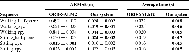
This section quantitatively evaluates the proposed VSLAM system with dynamic object elimination from the aspects of accuracy and efficiency and compares it with ORB-SLAM2. Six dynamic-object-containing sequences from the TUM dataset are selected for experiments on both systems. The framework executes each sequence 15 times to record localization accuracy and per-frame processing time, while Table II summarizes the results.
Comparison of ARMSE and average time taken.

Bold value denotes the statistically superior data or the most efficient performance values in each category.
As shown in Table II, the DynaFusionSLAM system achieves a significantly lower Absolute Root Mean Square Error (ARMSE) in high-dynamic scenarios than ORB-SLAM2, with an average accuracy improvement of 95.33%, while maintaining comparable precision in low-dynamic environments. Additionally, the system demonstrates marginally superior average time consumption across all tested sequences relative to ORB-SLAM2.
The comparison and analysis of the trajectories and relative pose errors (RPE) using the EVO evaluation tool [Reference Grupp26] are as follows:
Figure 9 compares the estimated trajectories of DynaFusionSLAM and ORBSLAM2 against the ground truth in two sequences. Figure 9(a) shows the projection of trajectories onto the XOZ plane for the walking_halfsphere sequence, while Figure 9(b) displays those on the XOY plane for the walking_xyz sequence. ORB-SLAM2 exhibits significant trajectory drift in highly dynamic environments, primarily due to feature points on moving objects that cause mismatches between feature tracking and actual motion, thereby degrading the pose estimation. In contrast, our system eliminates dynamic feature points and preserves the static ones, resulting in more accurate pose estimation that closely aligns with the ground-truth trajectory.
Trajectory comparison between ORB-SLAM2 and the proposed method relative to ground truth camera motion across sequences.

Comparison of RPE metrics for trajectory projections between ORB-SLAM2 and the proposed method across sequences.

Figure 10 presents the RPE data comparison of the two systems across the walking_halfsphere and walking_xyz sequences. The right graph illustrates the distribution of RPE values, while the left graph compares various RPE errors. The box plot analysis reveals that our system’s RPE distribution is tighter, with smaller error values in the concentrated region compared to ORB-SLAM2. The bar chart indicates that our system outperforms ORB-SLAM2 in six error metrics, including standard deviation (Std), root mean square error (RMSE), and minimum error (Min). These experimental results verify that our system achieves improved localization accuracy and stability, meeting the requirements for reliable localization and mapping set forth in this study.
3.4. Simulated map fusion performance
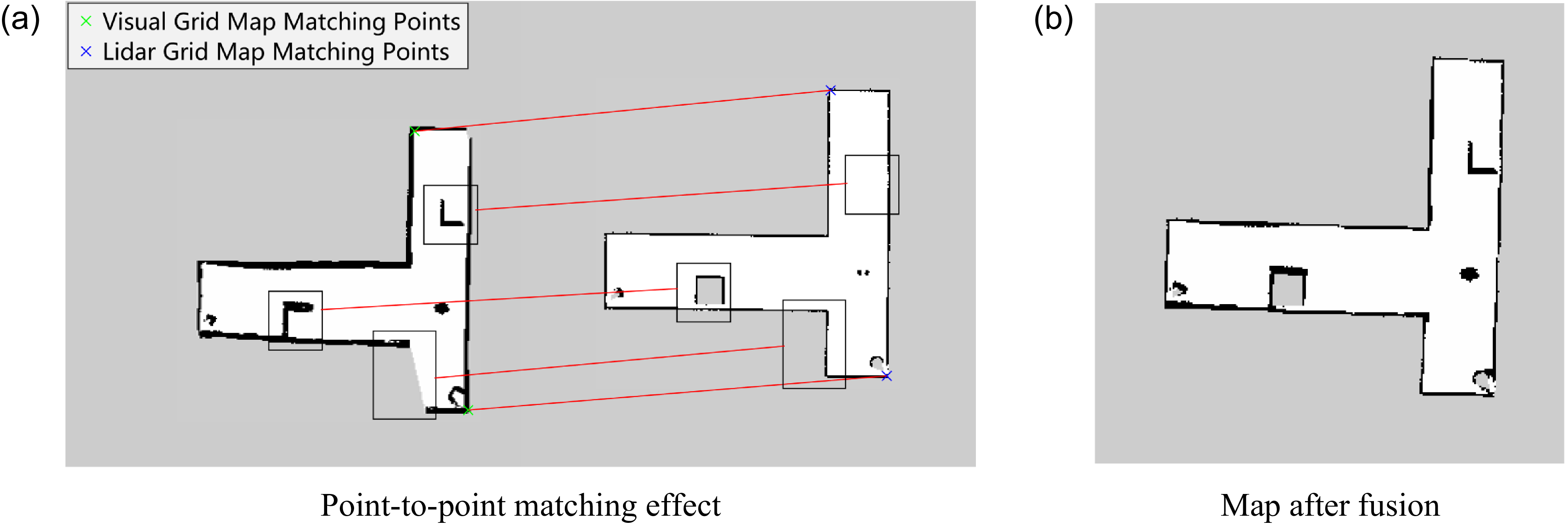
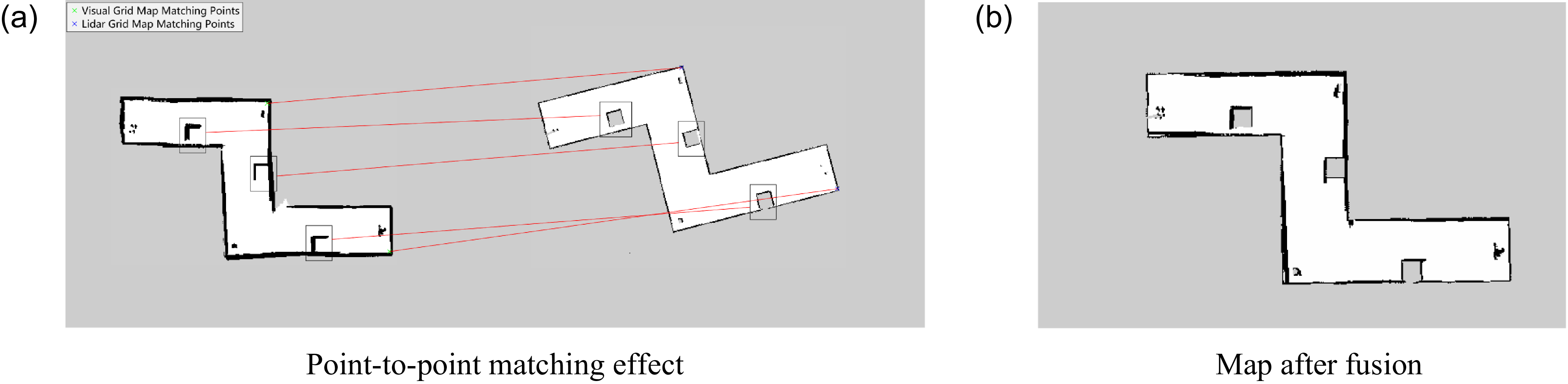
To verify the accuracy and effectiveness of the map fusion method, this study designed simulated environments for indoor corridor settings featuring U-shaped, T-shaped, and Z-shaped topologies (Figure 11), along with real-world mapping tests in dynamic corridor environments (Figure 15). The pipeline constructs LiDAR and visual grid maps for each scenario to simulate multi-modal fusion. Figures 12, 13, and 14 demonstrate the fusion results: (a) left panels display visual grid maps, while (b) right panels depict LiDAR grid maps, with (c) fused maps showing structural consistency. Figure 15 further validates the framework’s robustness through real-time mapping in dynamic corridors with moving pedestrians.
Simulation scene layout.

U-shaped corridor map fusion effect.

T-shaped corridor map fusion effect.

Z-shaped corridor map fusion effect.

LiDAR mapping result.

The simulation of the U-shaped corridor is shown in Figure 12. It can be observed that the limited field of view of the sensors led to unobserved areas in the top-left corner of the visual grid map, resulting in an incomplete map. After matching and fusing with the LiDAR grid map, as shown in Figure 12(b), the missing map information in the top-left corner is completed.
Figure 13 shows the simulation of a T-shaped corridor. In this experiment, an obstacle was placed outside the LiDAR’s detection range in the upper-right region. Figure 13(a) shows the laser grid map has clear scene boundaries but lacks obstacle information. The visual grid map records all obstacles but loses some wall corner details. Post-fusion mapping in Figure 13(b) accurately reconstructs all edges and multi-height obstacles, fulfilling the navigation requirements.
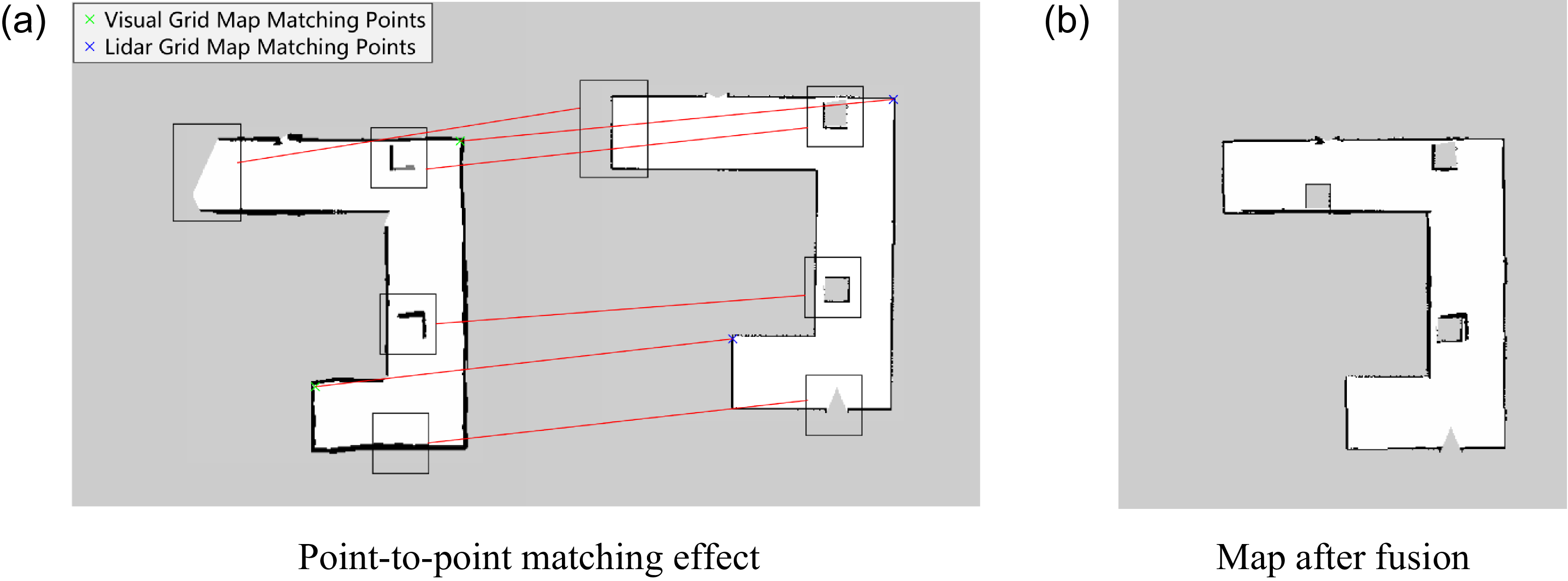
The simulation of the Z-shaped corridor is shown in Figure 14. Due to the different initial poses of the robot, a significant angular difference exists between the LiDAR and visual grid map in this scenario, as shown in Figure 14(a). Despite the initial pose discrepancy, the incorporation of rotational invariance into the BRIEF descriptor enables robust matching performance, particularly at inner corner points. The fused map, shown in Figure 14(b), further enhances structural details and improves overall map consistency.
3.5. Real-world map fusion performance
To verify the effectiveness of laser-vision fusion mapping in real-world scenarios, this paper uses a T-shaped corridor inside a building as the experimental environment. A window is located on the left side at one end of the corridor, while dynamic pedestrian activity is introduced on the right side, including individuals picking up objects in the hallway. A retractable barrier is placed at the far-end corner of the corridor to prevent the mobile robot from passing through the central area. By navigating the mobile robot along the corridor, sufficient point cloud data are collected from both LiDAR and a depth camera to construct a separate laser-based and a vision-based grid map.
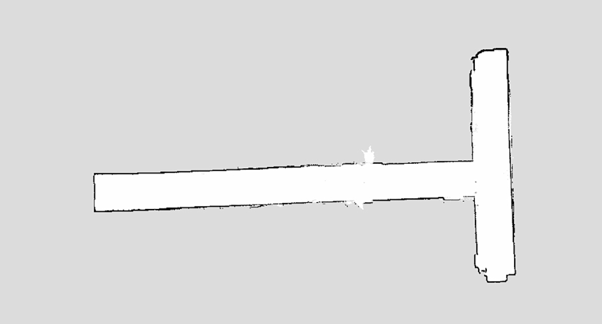
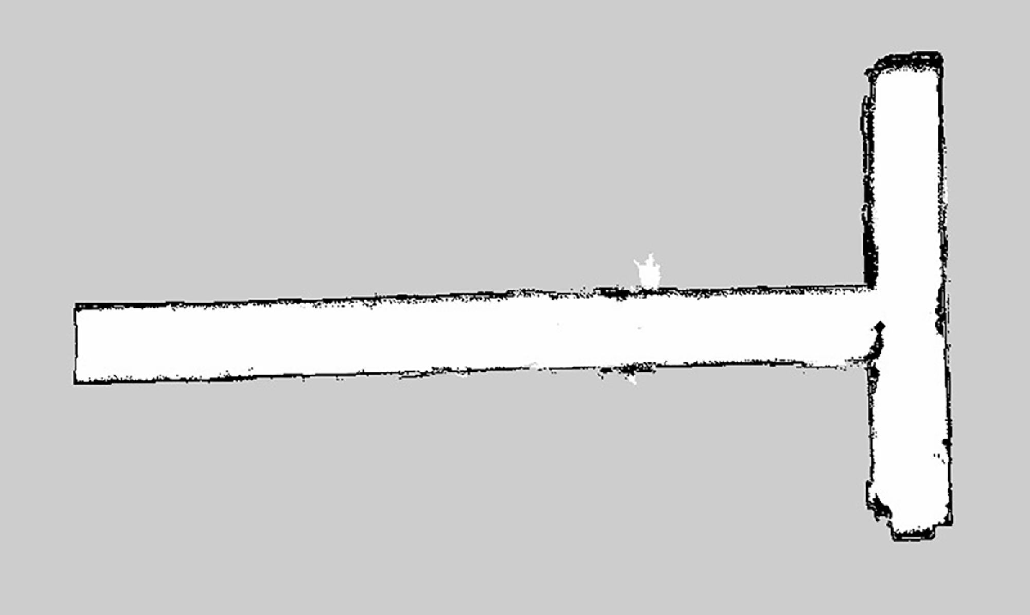
The LiDAR mapping was performed using the Cartographer algorithm, with the resulting map shown in Figure 15.
The results of dynamic feature elimination in visual mapping are demonstrated in Figure 16.
Dynamic object removal in visual mapping.

The actual dense point cloud reconstruction is shown in Figure 17. Originally, a pedestrian was moving near the doorway in the upper-left corner of the T-shaped corridor. However, it can be observed that the proposed framework successfully removes the pedestrian’s feature points from the point cloud map.
Visual point cloud map after dynamic object removal.

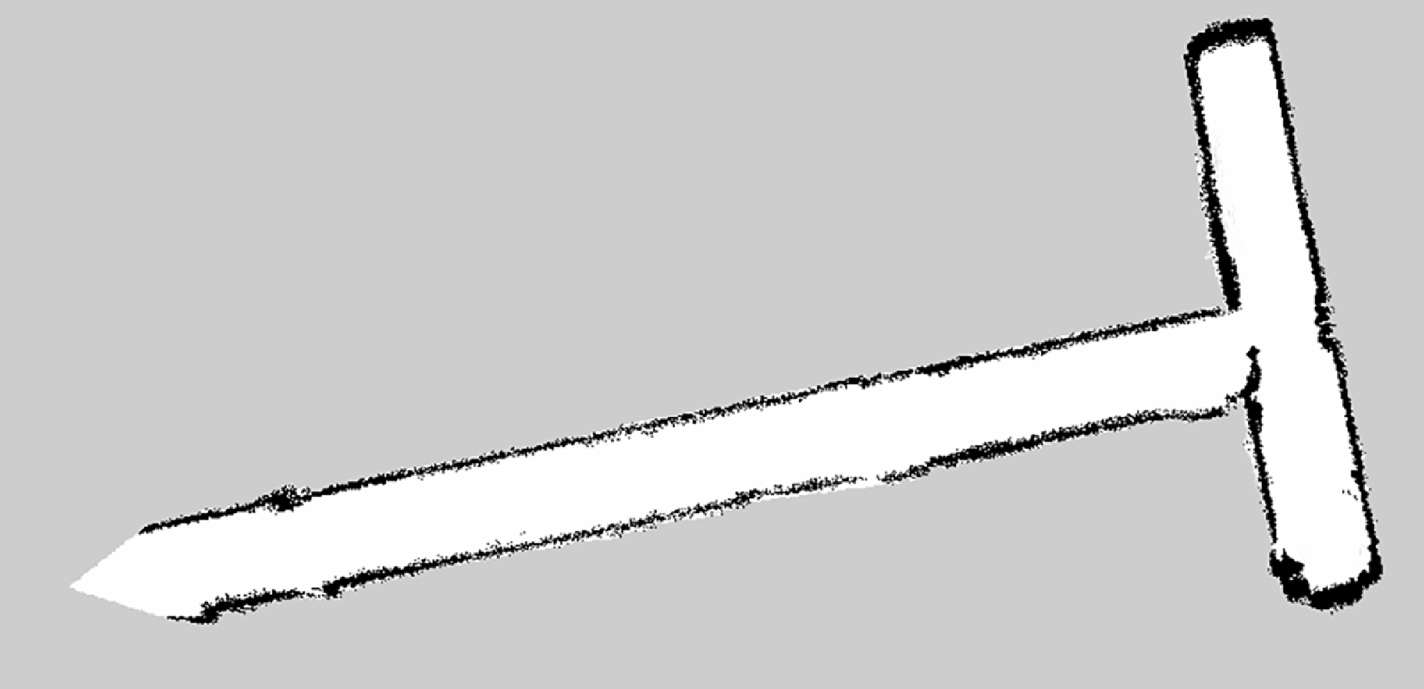
The final visual mapping result is shown in Figure 18. The 2D grid map further confirms that the dynamic features have been completely removed.
Visual mapping result.

The final fused LiDAR-visual mapping result is shown in Figure 19. The 2D grid map further confirms that the dynamic features have been completely removed, demonstrating the robust performance of our framework in this complex dynamic environment.
The experimental results demonstrate three key findings in the T-shaped corridor scenario: (1) Pedestrian features on the right path are completely removed from the point cloud map despite strong morning light interference from the left-side windows. (2) The improved feature extraction algorithm successfully obtains sufficient feature points on low-texture walls under intense illumination. (3) The visual map compensates for LiDAR’s inability to scan retractable barrier bases below its detection plane, while the LiDAR complements missing point cloud data in the initial corridor area caused by the camera’s limited field of view. The fused mapping achieves an effective environmental reconstruction with complementary sensor advantages.
4. Discussion and comparative analysis
This chapter presents a method for fusing laser SLAM and visual SLAM at the task level to address the issue of inaccurate environmental mapping caused by the limitations of laser and visual sensors. The proposed framework first eliminates dynamic objects using Mask R-CNN combined with multi-view geometry, thereby mitigating their impact on visual SLAM’s localization accuracy. Subsequently, an adaptive gamma correction algorithm is employed to enhance visual input quality, while a refined quadtree method optimizes feature distribution to improve the extraction of scene information. Experiments were conducted on multiple dynamic scene sequences in the TUM dataset, validating that the proposed visual SLAM system achieves improved accuracy while maintaining real-time performance compared to traditional algorithms. Finally, the proposed map fusion algorithm combines the grid map generated by visual SLAM with the grid map created by laser SLAM based on graph optimization, resulting in a more accurate grid map of the environment. The algorithm’s effectiveness is verified in multiple simulation environments, providing an accurate and reliable environmental map for subsequent path planning.
Although our experiments demonstrate the advantages of DynaFusionSLAM over ORB-SLAM2, its performance relative to other advanced dynamic SLAM systems – such as DynaSLAM, DS-SLAM [Reference Yu, Liu, Liu, Xie, Yang, Wei and Fei27], and R3LIVE [Reference Lin and Zhang28] – merits further discussion. A direct quantitative comparison remains challenging due to differences in sensor modalities and implementation frameworks. Thus, we provide a qualitative analysis based on methodological distinctions to highlight the unique advantages and potential performance of our approach. To facilitate a clearer comparison, Table III summarizes the key characteristics of these systems across several representative metrics.
Qualitative comparison of SLAM systems across key performance aspects.

Note: Ratings are based on methodological analysis and reported performance in respective studies.
DynaSLAM and DS-SLAM primarily rely on deep learning-based semantic segmentation (e.g., Mask R-CNN) for dynamic object removal. Although accurate, their computational expense and heavy dependence on GPU inference can hinder real-time performance on resource-constrained platforms. In contrast, DynaFusionSLAM combines semantic priors with efficient multi-view geometry checks. This hybrid strategy achieves robust dynamic elimination without over-reliance on computationally intensive segmentation models, thereby improving efficiency and real-time suitability.
Moreover, as purely visual systems, DynaSLAM and DS-SLAM remain susceptible to inherent challenges of visual SLAM, such as low-texture environments (e.g., corridors) and extreme illumination changes. A key advantage of DynaFusionSLAM lies in its multi-modal sensor fusion design. The integration of a LiDAR sensor provides precise geometric information that is invariant to lighting and texture conditions. The LiDAR-generated map provides a structurally stable prior, effectively compensating for the limitations of visual perception and ensuring robust performance in scenarios where purely visual systems are prone to failure.
Compared to the LiDAR-visual fusion system R3LIVE, our work specializes in structured indoor environments (e.g., corridors) and task-level map fusion. While R3LIVE excels at building dense, colorful maps, it often relies on a static world assumption or operates in relatively uncluttered scenes. In contrast, DynaFusionSLAM incorporates a corridor-optimized fusion strategy, leveraging improved Harris corner detection and Bayesian grid fusion to enhance structural fidelity and navigation accuracy in complex and dynamic indoor settings – a challenge not explicitly tackled by R3LIVE.
In summary, we argue that DynaFusionSLAM occupies a unique niche: it effectively balances computational efficiency and robustness by fusing semantic and geometric cues, while addressing a specific yet critical application scenario – dynamic corridors – through its optimized fusion strategy. A comprehensive quantitative comparison with these outstanding algorithms remains an important goal for our future research.
Fusion mapping result.

Author contribution
Yusong Zhou: conceptualization, data collection. Wentao Cheng: methodology, software, validation, formal analysis, investigation, visualization, and writing-original draft preparation. Xianlun Wang: resources, supervision, project administration. Yuxia Cui: review and editing.
Financial support
This research received no specific grant from any funding agency, commercial or not-for-profit sectors.
Competing interests
The authors declare no conflicts of interest exist.
Ethical approval
Not applicable.
Use of AI
During the preparation of this manuscript, the authors used artificial intelligence tools to assist with language polishing and grammatical checking. The tools used were ChatGPT (OpenAI, GPT-3.5–based publicly accessible web version, accessed via https://chat.openai.com). No AI tools were used in the research design, data analysis, interpretation of results, or generation of scientific content. All authors have read and approved the final version of the manuscript and take full responsibility for its content.