Introduction
The objective was to study the characteristics of Isorad diodes in-vivo dosimetry system for photons and then to perform in vivo dosimetry of patients visiting our radiotherapy department in order to check accuracy of dose delivery as per treatment plan generated through treatment planning system. The intention is to replace thermo luminescent dosimeter, which is a passive dosimeter, time consuming, and is an inconvenient method for patient dose verification/monitoring. With diode dosimetry system, the dose delivered to planning target volume can be instantly verified.Reference Meigooni, Sowards and Myron1–Reference Essers and Mijnheer7 The diode signal depends upon photon energy, dose rate, temperature, geometric parameters, phantom scatter; head scatter electrons and build up cap. Geometric parameters, e.g. source to surface distance (SSD), field sizes (FSs), angular variation, presence of wedges and block trays change the dose response of diode, therefore, corrections are required because of a change in dose rate, head scatter electrons, attenuation of beam energy and temperature variation. If build up cap of diode is not thick enough then an overestimation of dose at short SSD can be observed because of the electronic contamination seen by diode not IC at maximum depth dose. In order to minimise the number of correction factors, thickness of buildup cap should be equal to depth of maximum dose because the response of diode changes with the shape and thickness of buildup cap, e.g. thick build up cap perturbs radiation dose below it in the treatment area. Therefore correction factors have to be applied which can take all geometric parameters into account.Reference Fontenla, Yaparpalvi, Chui and Briot8, Reference Huyskens, Bogaerts and Verstraete9
Potential sources of error are diode calibration, manual or computerised treatment planning, setup of patient or phantom and motion.Reference Howlett, Duggan, Bazley and Kron10, Reference Alecu, Loomis, Alecu and Ochran11 Verification of dose delivered to patients plays an important role in the improvement of radiotherapy skills and quality assurance in radiotherapy.Reference Banjade, Aloysius Raj, Ng, Xavier, Tajuddin and Shukri12–Reference Appleyard, Ball and Hughes14 In our study, in vivo dosimetry was performed with a specific diode for Co-60 beam energy so that it might be used clinically for the same energy later on.Reference Meiler and Podgorsak15 Some important preliminary tests and correction factors including obliquity and wedge were calculated because of beam attenuation of n-type Isorad diode in order to use these factors for in vivo dosimetry.Reference Fontenla, Yaparpalvi, Chui and Briot16–Reference Allahverdi, Mohammadkarim, Esfehani, Nedaie, Shirazi and Geraily20
Materials and methods
An n-type Isorad diode (Sun Nuclear Corporation, Melbourne, Australia) was used having sensitive volume of 0·25 mm3, diameter 7·1 mm along with an electrometer (patient dose monitor (PDM), Model No. 37-721, Nuclear Associates, NA, USA), which is a dual channel diode dosimetry system.
IC, PTW Frieburg TW30013, 0114 was used along with an electrometer (Model CNMC, USA). Treatment planning system Multidata DSS 2.5 was used to calculate time for Co-60 beam. In our study, ATOM Adult Male Human Phantom (Model 701-D, CIRS, USA) was used for verification of radiation dose delivery. The design of human phantom was sectional consisting of slices with slab thickness of 25 mm. The sectional surfaces were flat, smooth and contain the organ simulated in real human. Reference conditions mean SSD 80 cm, FS 10 × 10 cm2, collimator angle 0° and gantry angle 0° and standard dose mean 100 cGy.
Following is the list of tests, which were performed on n-type Isorad diode before its use for in vivo dosimetry.
(1) Calibration of detector channel of patient dose monitor (PDM).
(2) Collimator and FS matching test.
(3) Reliability and stability of equipment test.
(4) Signal stability test.
(5) Precision test.
(6) Response/dose linearity test.
(7) Perturbation of radiation field.
(8) Effect of Styrofoam thickness
(9) Plastic to water conversion factor (K pl).
(10) Diode calibration.
(11) Correction factors:
(a) FS correction factor.
(b) Block tray correction factor.
(c) Wedge correction factor.
(d) SSD correction factor.
(e) Angle correction factor.
(f) Block correction factor.
(12) Verification procedures:
(a) Study of change in FS.
(b) Change in wedge.
(c) Point doses at various reference points.
Calibration of detector channel of PDM
The steps involved in calibration of PDM are as follows:
(1) The machine ID 111 was entered with help of 6-keypad on PDM. Out of three radiation types, i.e. photons, electrons, Co-60, the last beam quality was selected. Out of two channels detector group 05 of only one channel was selected to irradiate Isorad diode with Co-60 beam. Channel serial number 11700 was entered with help of keypad. PDM then starts adjusting offset voltage to reduce leakage current.
(2) Option for irradiation is displayed on LCD of PDM. START key was pressed before radiation was on; similarly STOP key was pressed after the radiation was stopped to ensure good accuracy and remove any uncertainty in delivery of 100 cGy dose. This target is achieved after the threshold of channels has crossed, i.e., conversion of ‘NO’ to ‘YES’ on LCD of PDM. Out of two options of radiation units ‘Rad’ or ‘cGy’ for reading and printout purposes, the option of ‘cGy’ was selected.
(3) After radiation dose delivery to Isorad diode attached to PDM, a calibration factor 8·013 × 10−4 is shown by PDM against the selected channel number. It was used in all subsequent measurements by PDM itself. This calibration was performed in the same way at which diode is to be used in the subsequent tests, i.e. the diode connected to channels during calibration was always reconnected to same channels during measurements.
Collimator and FS matching test
Phoenix, Theratron provided standard chart carrying FSs marked over it from 5 × 5 to 40 × 40 cm2. This test is very simple and involves following steps:
(1) The cross of collimator opening and FS provided by machine manufacturer were matched.
(2) Collimators (X and Y jaws) were opened for various FSs. The square opening of collimator is matched with square FS available over the chart.
Reliability and stability of equipment test
Before using diode, this test was performed for two weeks. Diode was positioned at the central axis (CAX) of field over the top of plastic phantom 30 × 30 × 2·245 cm3. Diode was irradiated ten times under reference conditions for standard dose and readings were noted.
Signal stability test
Whenever the diode is connected to PDM, the diode response may be influenced by leakage current, therefore ‘signal stability test’ was performed to check variation in the response of diode after a certain warm-up time when irradiated with standard dose under reference conditions. Diode is placed at CAX over top surface of the above-stated plastic phantom. In order to simulate clinical scenario of in vivo dosimetry for patients, signal readings were noted two times, First reading, after irradiation and second reading after time interval of 5 minutes.
Precision test
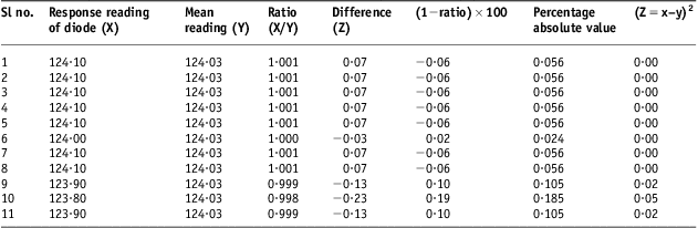
In this test, the diode was irradiated for 1 minute under reference conditions. The diode is placed at CAX on the top surface of plastic phantom, 11 readings were taken and mean standard deviation and percentage variation of data was calculated.
Dose response linearity test
In this test, the dose (20–300 cGy) was delivered to diode which was positioned at CAX on surface of plastic phantom under reference conditions and response of diode was noted for various radiation doses delivered to diode by using Co-60 beam and a graph was plotted.
Perturbation in field symmetry
The Isorad diode absorbs certain amount of radiation dose because of the build-up cap in order to generate its signal. Therefore perturbation in the dose symmetry is observed below Isorad diode. IC placed at CAX and depth of 5 cm in plastic phantom 30 × 30 × 11 cm3 was irradiated with standard dose and repeated with the diode placed at CAX on the top surface of phantom. In this test, Styrofoam of 2 mm thickness was used integrated with Isorad diode.
Field flatness test at d max
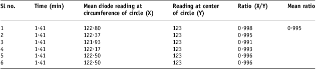
In this test, plastic phantom with dimensions of 30 × 30 × 2·245 cm3 was used. Under reference conditions and standard dose, the diode readings were taken by placing diode at CAX and at the circumference of circle (radius of 2·4 cm). The ratio of diode readings was taken to see field flatness.
Effect of Styrofoam thickness
‘Styrofoam’ (2 mm thickness) was used to avoid the effect of temperature variations in diode measurements when in contact with the surface of plastic phantom. IC was placed at the CAX and 5 cm depth in plastic phantom whereas the diode (integrated with Styrofoam on the lower surface of Isorad diode) was placed over the top surface of phantom. Both dosimeters were irradiated for standard dose and variation in dose at d max because of Styrofoam under reference setup was calculated.
Plastic to water conversion factor (K pl)
This factor is required to convert diode reading in plastic to diode reading in water. As the properties of material/medium are changing, therefore standard dosimeter, IC was used instead of diode. While determining plastic to water conversion factor, IC was placed at CAX and 5 cm deep in plastic phantom. IC was irradiated for 1 minute under reference condition and reading in plastic phantom (M pl) was noted. Similarly, gantry was rotated to 90° and IC being at CAX was irradiated 5 cm deep in water phantom. Reading in water phantom (M w) was noted. The charge collected by IC is converted into dose and readings were corrected for temperature and pressure by applying K TP factor.
Diode calibration factor (F cal)
Before starting, diode was irradiated for standard dose at CAX and off-axis for reference setup, and difference in the diode response because of such variation was noted to justify off-axis position of Isorad diode for ‘diode calibration’.
In this test, the IC was placed at CAX, 5 cm deep in plastic phantom. The diode was placed at a distance of 1·4 cm from central beam axis (off-axis) on the phantom surface. Diode and IC both were irradiated for standard dose under reference setup simultaneously. Reading of IC at 5 cm is converted into reading at d max. Temperature and pressure corrections were applied on IC reading:
 $${{F}_{{\rm{cal}}}}\, = \,\frac{{{\rm{IC}}\,{\rm{reading}}}}{{{\rm{Diode}}\,{\rm{reading}}}}\eqno\rm$$
Correction factors for Isorad diodes
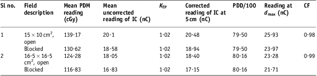
Field size correction factor (CF FS)
Field size correction factor (CF FS; subscript FS stands for field size) is required to include the difference in scatter conditions faced by IC at d max and by diode taped at surface of phantom. A change in FS causes change in d max and thus causes uncertainty in calculations.
Diode and IC were exposed at CAX for irradiation time calculated for standard dose under reference conditions. The diode and IC were placed on the surface and 5 cm deep in plastic phantom 30 × 30 × 11 cm3 for FSs 15 × 15 and 5 × 5 cm2. The corresponding readings of ionisation chamber F IC(r) and diode F diode (r) were noted for ‘r’ field size.
Similarly, the plastic phantom is exposed under the same conditions for FS 10 × 10 cm2 and corresponding values were noted for ionisation chamber F IC (10) and diode F diode (10):
 $$C{{F}_{{\rm{FS}}}}\, = \,\frac{ \displaystyle{\frac{{{{F}_{{\rm{IC}}}}\,{\rm{(}}r{\rm{)}}}}{{{{F}_{{\rm{IC}}}}{}\,{\rm{(10)}}}}}}{\displaystyle{\frac{{{{F}_{{\rm{diode}}}}\,{\rm{(}}r{\rm{) }}}}{{{{F}_{{\rm{diode}}}}\,{\rm{(10)}}}}}}\eqno\rm$$
‘r’ stands for field size 15 × 15 or 5 × 5 cm2.
Source to surface distance correction factor (CF SSD)
Diodes are sensitive to dose rate. A correction factor for SSD, CF SSD, is required to account for electron contamination and dose rate changes with SSD.
The IC and diode were exposed at CAX at fixed FS (10 × 10 cm2) for three different SSDs 80, 85 and 75 cm at irradiation time calculated for standard dose under reference conditions. IC was placed 5 cm deep in plastic phantom whereas diode was exposed on the surface of plastic phantom. IC readings were corrected back for d max. The following formula was applied to get correction factor:
 $$C{{F}_{{\rm{SSD}}}}\, = \,\frac{{{{R}{^{\prime}}_{{\rm{IC}}}} }}{{{{R}{^{\prime}}_{{\rm{diode}}}} }}\eqno\rm$$
 $${{R^{\prime}}_{{\rm{IC}}}}\, = \,\frac{{{{R}_{{\rm{IC}}}} \ ({{d}_{\max }},{\rm{10}}\,\times \,{\rm{10}}\,{\rm{c}}{{{\rm{m}}}^{\rm{2}}} {\rm{,}}\,{\rm{selected}}{\rm{.SSD}})}}{{{{R}_{{\rm{IC}}}} \ ({{d}_{\max }},{\rm{10}}\,\times \,{\rm{10}}\,{\rm{c}}{{{\rm{m}}}^{\rm{2}}} {\rm{,}}\,{\rm{80}}\,{\rm{cm}})}}\eqno\rm$$
 $${{R^{\prime}}_{{\rm{diode}}}}\, = \,\frac{{{{R}_{{\rm{diode}}}} \ ({\rm{10}}\,\times \,{\rm{10}}\,{\rm{c}}{{{\rm{m}}}^{\rm{2}}} {\rm{,}}\,\,{\rm{selected}}{\rm{.SSD}})}}{{{{R}_{{\rm{diode}}}} \ ({\rm{10}}\,\times \,{\rm{10}}\,{\rm{c}}{{{\rm{m}}}^{\rm{2}}} {\rm{,}}\,{\rm{80}}\,{\rm{cm}})}}\eqno\rm$$
R′ represents ‘ratio’ and R represents ‘reading’.
Angle correction factor (CF angle)
CF angle is required in the situations where the sensitive area of diode faces beams at angular positions, diode receives different amount of radiation at angular positions thus a change in the response of diode may be observed.
The diode was irradiated over the top surface of plastic phantom under reference setup and standard dose. Correction factor was calculated for various angles (left lateral anterior oblique 60° to right lateral anterior oblique 120°):
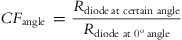 $$C{{F}_{{\rm{angle}}}}\, = \,\frac{{{{R}_{{\rm{diode}}\,{\rm{at}} \ {\rm{certain}} \ {\rm{angle}}}}}}{{{{R}_{{\rm{diode}}\,\,{\rm{at}}\,\,{{{\rm{0}}}^{\rm{o}}} \,{\rm{angle}}}}}}\eqno\rm$$
where R stands for reading, the average of all the values was found and this average value of correction factor (CF angle) was used in all the measurements involving angular positions of diode.
Wedge correction factor (CF wedge)
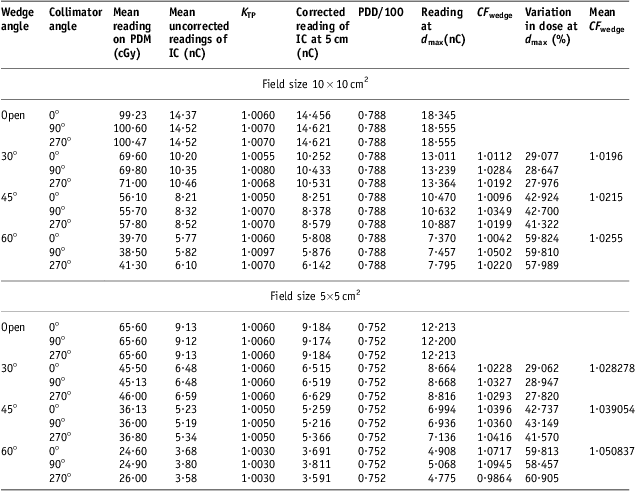
Wedge alters dose rate and causes beam hardening in energy spectrum. The sensitivity of diode is affected with dose rate and energy. The wedges used for calculation of this factor were having dimension of 10 W × 15 at 80 cm SSD. Two-FSs 5 × 5 and 10 × 10 cm2 and wedges 30°, 45° and 60° were used.
At first SSD and FS was set at 80 cm and 10 × 10 cm2, respectively, and then FS was changed to 5 × 5 cm2. The angles of collimator and gantry were set at 0° in both cases. For 10 × 10 cm2 FS, the diode and IC were irradiated with standard dose. For FS 5 × 5 cm2, data was collected for 1-minute irradiation time.
The diode readings were taken with open and wedged beams at 0°, 90° and 270° collimator angles and the same was done with IC, placed at 5 cm depth in plastic phantom.
Correction factor is determined by applying following formula:
 $$C{{F}_{{\rm{wedge}}}}\, = \,\frac{{R_{{{\rm{IC}}}}^{{\prime\prime}} }}{{R^{{\prime\prime}}_{{{\rm{wedge}}}} }}\eqno\rm$$
 $${R{{\rm{''}}}_{{{\rm{IC}}}}{} \, = \,\frac{{{{R}_{{\rm{IC}}}} \ ({{{{d}}}_{{\rm{max}}}}{\rm{,}}\ selected.FS, \ SSD\, {\rm{(80\,cm),}}\,{\rm{wedge}}{\rm{.angle}})}}{{R_{{{\rm{IC}}}}{{{\rm{}}}} \,({{{{d}}}_{{\rm{max}}}}{\rm{,}} \ selected.FS,SSD)}}\eqno\rm$$
 $${\rm{R}}{{{\rm{''}}}}_{{{\rm{diode}}}} \, = \,\frac{{{{R}_{{\rm{diode}}}}\,(selected.FS,SSD \ {\rm{(80\,cm),}}\,{\rm{wedge}}{\rm{.angle}})}}{{{{R}_{{\rm{diode}}}}\,(selected.FS,SSD)}}\eqno\rm$$
Selected FS means 10 × 10 or 5 × 5 cm2. R′′ represents ‘ratio’ and R represents ‘reading’. IC represents ionisation chamber. Temperature and pressure corrections were also applied to IC readings.
Block tray correction factor (CF tray)
Inserting a block tray inbetween source and patient changes the amount of electrons reaching patient skin thus a block tray changes the dose.
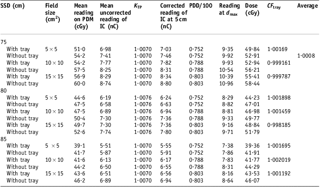
CF tray is affected because of change in SSD and FS. Different SSDs 85, 80 and 75 cm and FSs 5 × 5, 10 × 10 and 15 × 15 cm2 were included in calculation of this factor for irradiation time of 0·72 minutes calculated for 50 cGy at d max at 10 × 10 cm2. Diode and IC readings were taken at different SSDs and FSs with and without tray. The collimator and gantry were set at 0°.
The IC charge at 5 cm depth in plastic phantom is corrected back at d max. Temperature and pressure correction factor K TP was used to include effect of temperature and pressure variation. Correction factor is determined as
 $$C{{F}_{{\rm{tray}}}}\, = \,\frac{\displaystyle{\frac{{{{R}_{{\rm{IC}}}}\,({{d}_{\max }},F{{S}_{{\rm{selected}}}}, SS{{D}_{{\rm{selected}}}}{\rm{, tray}})}}{{{{R}_{{\rm{IC}}}}\,({{d}_{\max }},F{{S}_{{\rm{selected}}}}, SS{{D}_{{\rm{selected}}}})}}}}{\displaystyle{\frac{{{{R}_{{\rm{diode}}}}\,(F{{S}_{{\rm{selected}}}}, SS{{D}_{\rm selected}}{\rm{, tray}})}}{{{{R}_{{\rm{diode}}}}\,(F{{S}_{{\rm{selected}}}}, SS{{D}_{{\rm{selected}}}})}}}}\eqno\rm$$
Evaluation of percentage variation in dose due to tray was also calculated for standard dose in reference setup.
Block correction factor (CF block)
CF block was calculated to check response of diode when blocks are used to shield normal tissues. The idea behind it was to correct the diode reading for cerroband shielding block, which are used while implementation of various treatment plans on patients. Diode was placed over the top surface of plastic phantom at central beam axis.
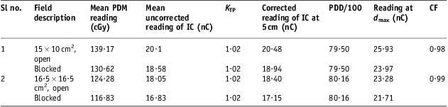
SSD, FS and irradiation time, in the first case, were set at 80 cm and 15 × 10 cm2, 1·97 minutes and then 80 cm, 16·5 × 16·5 cm2 and 1·70 minutes, respectively, in the second case. The angles of collimator and gantry were set at 0°. Diode readings and IC readings were taken at CAX with open and blocked beams for cases 1 and 2 stated above. Following formula was applied to calculate correction factor
 $$C{{F}_{{\rm{block}}}}\, = \,\frac{\displaystyle{\frac{{{{R}_{{\rm{IC}}}} \ ({{d}_{\max }},selected.FS{\rm{, }}\,{\rm{open}})}}{{{{R}_{{\rm{IC}}}} \ ({{d}_{\max }},selected.FS{\rm{, }}\,{\rm{blocked}})}}}}{\displaystyle{\frac{{{{R}_{{\rm{diode}}}} \ (selected.FS{\rm{,}}\,{\rm{open}})}}{{{{R}_{{\rm{diode}}}} \ (selected.FS{\rm{,}}\,{\rm{blocked}})}}}}\eqno\rm$$
where R IC and R diode means, ‘Reading with ionisation chamber and diode respectively’.
Linearity test
Radiation damage may change the diode response with passage of time. Diode and IC readings were taken at three SSDs (85, 75, 80 cm). IC and diode were irradiated with standard dose at CAX and kept at 5 cm depth and top surface of plastic phantom, respectively. IC reading was also corrected back to d max:
 $${\rm{Linearity}}\,{\rm{value}}\,{\rm{ = }}\,\frac{\displaystyle{\frac{{{{R}_{{\rm{diode}}}} \ (10\times10\,{\rm{c}}{{{\rm{m}}}^2} {\rm{, SSD}})}}{{{{R}_{{\rm{diode}}}}\ (10\times 10\,{\rm{c}}{{{\rm{m}}}^2} {\rm{, SSD}}\,{\rm{ = }}\,{\rm{80\,cm}})}}}}{\displaystyle{\frac{{{{R}_{{\rm{IC}}}} \ ({{d}_{\max }},10\times 10{\rm{\,c}}{{{\rm{m}}}^2} {\rm{, SSD}})}}{{{{R}_{{\rm{IC}}}} \ ({{d}_{\max }},10\times 10\,{\rm{c}}{{{\rm{m}}}^2} {\rm{, SSD}}\,{\rm{ = }}\,{\rm{80\,cm}})}}}}\eqno\rm$$
where R IC and R diode means, ‘Reading with ionisation chamber and diode respectively’.
Verification of correction factors human phantom
Various tests were designed in the form of point calculations in order to verify above correction factors. The irradiation time was calculated in human phantom with different reference depths, FSs and wedge. The objective of tests before implementation of in vivo dosimetry on patients was to verify the dose calculated with TPS Multidata Decision Support System 2.5 chart calculator and measurement of this given dose on easily viable sites of human phantom (nasopharynx and lung) where placing and positioning of diode was relatively easy compared with other sites on the human phantom in order to reduce positioning-related error in diode response.
Verification of point doses at reference depth variation (SSD and angle correction factor)
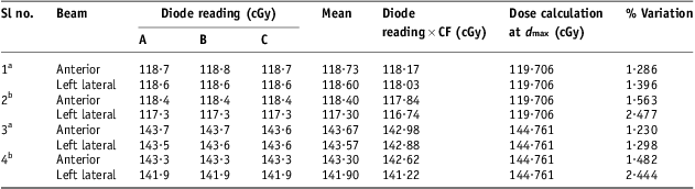
In this study, irradiation time for 100 cGy at 80 cm SSD, 10 × 10 cm2 FS was calculated for points at different calculation depth (0·5, 4 and 7 cm). The effect of gantry rotation was also associated in this study to include angle correction factor. So diode reading was multiplied with correction factors (SSD and angle), plastic to water conversion factor and calibration factor in this test. The collimator angle was set at 0° (Tables 12 and 13).
Data for verification studies on d max

Notes: aStudy site nasopharynx, bStudy site lung.
Abbreviation: IC, ionisation chamber.
Evaluation of percentage variation in dose at various reference depths
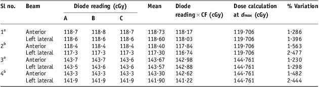
Notes: aStudy site nasopharynx at 4 cm, bStudy site lung at 7 cm.
Abbreviation: IC, ionisation chamber.
Verification of FS correction factor
This check was performed using anterior and lateral beams of Co-60. SSD was set at 80 cm and time was calculated for 100 cGy dose at 5 cm depth. This time was found to be 1·72 minutes in TPS. FS was changed from 10 × 10 to 12 × 17·5 cm2. So diode reading was multiplied with correction factor, plastic to water conversion factor and calibration factor in this verification. The collimator angle was set at 0° (Table 14).
Evaluation of percentage variation because of variation of field size

Notes: aStudy site nasopharynx at field size 12 × 17·5, bStudy site lung at field size 12 × 17·5.
Abbreviation: IC, ionisation chamber.
Verification of wedge correction factor (wedge correction factor)
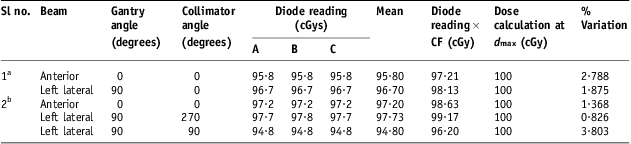
Keeping SSD at 80 cm, FS at 10 × 10 cm2, time for 100 cGy dose at d max was calculated for 30° having dimension 10 W × 15 wedges in Co-60. This time was found to be 2 minutes. This study was performed at various gantry and collimator angles (Table 15).
Evaluation of percentage variation because of 30° wedge at various collimator angles
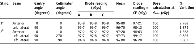
Notes: aStudy site nasopharynx, bStudy site lung.
Abbreviation: IC, ionisation chamber.
Results and discussions
Reliability and stability of equipment
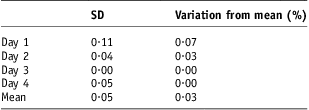
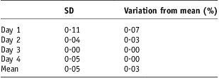
The average value of standard deviation and variation from the mean reading in diode readings are 0·050 and 0·030, respectively, and data is presented in Table 1.
Evaluation of mean (SD) and percentage variation of data collected in two weeks
Abbreviation: SD, standard deviation.
Signal stability after irradiation
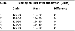
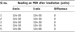
Constancy in all the diode readings was found before and after interval of 5 minutes (Table 2).
Diode response with and without gap
Abbreviation: PDM, patient dose monitor.
Precision test
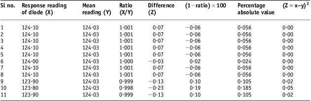
The precision data obtained with the Isorad diode indicated percentage variation of data to be 0·074% showing that the precision of diode data is acceptable as presented in Table 3.
Evaluation of standard deviation for precision test
Response/dose linearity check
The response of diode was found proportional to absorbed dose for curative irradiation range (20–300 cGy) as shown in Figure 1.
Dose response linearity curve.

Field flatness test
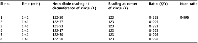
The mean ratio between the diode reading at the circumference and center of circle is 0·995 giving a non-uniformity of 0·500% presented in Table 4.
Data collected for beam flatness
Perturbation in field symmetry
It has been found while evaluation of variation in dose due to diode/perturbation of diode in radiation field that Isorad diodes specific for Co-60 beam cause a variation of 5% in dose at d max.
Effect of Styrofoam
The percentage variation found in dose because of Styrofoam is 0·300% showing that effect of Styrofoam is negligible in dosimetry.
Diode calibration
Diode readings had been taken at central axis and at off-axis (1·4 cm from central axis); the percentage variation of 0·299% was found in diode response, which justifies the use of Isorad diode at off-axis and allows simultaneous irradiation with IC. The diode calibration factor, 0·989, was found.
FS correction factor
Correction factor for FS was calculated for two-FSs 15 × 15 and 5 × 5 cm2. In both cases the results have been found close to unity. The mean value was found out to be 1·001 (Table 5).
Data collected for calculation of field size CF

Abbreviations: CF, correction factor; PDM, patient dose monitor; IC, ionisation chamber; PDD, percentage depth dose.
SSD correction factor
Data for two different SSDs has been taken. The correction factor was found with both of SSDs and it is presented in Table 6. In this case the CF SSD was found as 1·000 and 0·994 with the mean value of 0·997 close to one.
Determination of CF SSD

Abbreviations: CF, correction factor; SSD, source to surface distance; PDM, patient dose monitor; IC, ionisation chamber; PDD, percentage depth dose.
Block tray correction factor
Average correction factor for tray (CF tray) was 1·001 close to unity. Using this tray in-between phantom and source causes a variation of 6·000% at d max in dose delivery to the Isorad diode placed at the surface of phantom (presented in Table 7).
Data collected for calculation of CF tray
Abbreviations: CF, correction factor; SSD, source to surface distance; PDM, patient dose monitor; IC, ionisation chamber; PDD, percentage depth dose.
Wedge correction factor
Data obtained for wedge factor or wedge correction factor (CF wedge) has been presented in Table 8. It has been found to play considerable role in the Isorad diodes dose response. The mean value of CF wedge for 30°, 45° and 60° wedges is 1·024, 1·030 and 1·038, respectively. As CF wedge depends upon FS therefore its effect was also observed. Collimator angles of 90° and 270° were taken into consideration during our study because, in the clinical implementation, these collimator angles are significant.
Calculation of CF wedge for different collimator angles, i.e. 10 × 10 and 5 × 5 cm2 for 10 W × 15
Abbreviations: CF, correction factor; PDM, patient dose monitor; IC, ionisation chamber; PDD, percentage depth dose.
In Table 8, the dose variation for wedges of 30°, 45° and 60° was calculated for two different FSs. The percentage mean variation in dose because of the presence of wedge between source and phantom at different collimator angles was calculated. It was found that 30° wedge causes variation in dose up to 29·0%, 45° wedge causes 42·3% and 60° wedge causes variation of 59·2% in dose at d max when dose is delivered to the detector placed at the surface of phantom.
Block correction factor
Table 9, the average value of block correction factor was found to be 0·990. This block correction factor will be required to correct the dose for the block when used to shield normal tissues.
Evaluation of block CF
Abbreviations: CF, correction factor; PDM, patient dose monitor; IC, ionisation chamber; PDD, percentage depth dose.
Angle correction factor
Angle correction factor was evaluated and found to be 1·006 for Isorad diode. The average has been calculated for relative response. The variation in correction factor at various angles has been shown graphically in Figure 2. The range of variation between maximum and minimum is 1·00–1·02.
Relative response of diode with gantry angle (degrees).
Linearity test
Linearity test was performed two times with an interval equal to the length of study, i.e. first test was performed at the beginning of the Isorad diodes dosimetry and second time at the end of dosimetry (Tables 10 and 11). The ratio of IC and diode readings at d max of 75 cm SSD was found 0·02% on higher side in our second attempt to check linearity test.
Evaluation of linearity at different SSDs in first check

Abbreviations: SSD, source to surface distance; PDM, patient dose monitor; IC, ionisation chamber; PDD, percentage depth dose.
Linearity evaluation in second attempt

Abbreviations: SSD, source to surface distance; PDM, patient dose monitor; IC, ionisation chamber; PDD, percentage depth dose.
Verification of correction factors human phantom
These tests were performed over phantom tissues to verify the diode results for above calculated factors. The results of each test are as follows.
Study of dose at various reference points
Three reference points were selected for this study. In this test, the time of irradiating the diode for 100 cGy at d max, 4 cm and 7 cm was set at 1·43, 2·00 and 2·06 minutes, respectively. The percentage variation in dose calculation has been found within the range of 0·380–1·670% at d max, 1·290–2·480% at 4 cm, 1·230–2·440% at 7 cm by applying CF SSD along with diode calibration (F cal) and plastic to water conversion factor (K pl):
 $${\rm{Dose}}\,{\rm{ = }}\,{\rm{Diode}}\;{\rm{reading}}\,\times \,C{{F}_{{\rm{SSD}}}}\,\times \,{{F}_{{\rm{cal}}}}\,\times \,{{K}_{{\rm{pl}}}}\eqno\rm$$
Change in FS
The percentage variation in dose evaluation 1·190–2·066% because of the change in FS (10 × 10 to 12 × 17·5 cm2) has been presented in Table 14. Only FS correction factor (CF FS) was used along with calibration factor (F cal) and plastic to water conversion factor (K pl) in order to calculate diode reading at d max. SSD was set at 80 cm:
 $${\rm{Dose}}\,{\rm{ = }}\,{\rm{Diode}}\;{\rm{reading}}\,\times \,C{{F}_{{\rm{FS}}}}\,\times \,{{F}_{{\rm{cal}}}}\,\times \,{{K}_{{\rm{pl}}}}\eqno\rm$$
Effect of wedge
In order to study and verify the effect of wedge, 30° wedge was used. This variation ranges 0·83–3·80%. However at gantry angles of 90° and collimator angle of 90°, the effect of wedge has been boosted up. The results have been detailed in Table 15. The possible causes of variation in dose evaluation in these tests are because of positioning/placement error of diode on phantom surface, due to setup error or change in position of diode when kept and removed again and again for taking readings on lateral and anterior sides of nasopharynx and lung.
Discussion
The results of reliability and stability interprets that Isorad diode with PDM and machine setup was highly reliable and stable. Isorad diode detector (n-type) shows very good compatibility with electrometer (PDM). Out of 11 readings taken for precision test, the difference of seven readings with the mean reading was 0·070 giving precise results when diode was irradiated under reference conditions. The Figure 1 indicates that the dose response linearity for Isorad diode exists in clinical dose range. The linearity in dose response curve of this diode states good condition of diode and it is following linearity and dose reproducibility discussed for diodesReference Fontenla, Yaparpalvi, Chui and Briot16 making it a good tool for in vivo dosimetry of patients. A variation of 0·500% in beam flatness may be non-uniformity due to bending of Isodose curves away from the centre of Co-60 beam.
Before using diode and IC at CAX one above the other, perturbation in dose area was calculated by placing IC either at d max or 5 cm below diode. This parameter has been found to be 5·000% in our study (which can lead to erroneous results if such setup is used accidentally) calculated for determination of diode characteristics especially when both are used together at CAX. This justifies why we need to put diode away from CAX when IC is placed below during calibration of diode. Such studies have been performed also on other Isorad diodes.Reference Alecuv, Feldmeier and Alecu21
Two-millimetre-thick Styrofoam was used with diode in order to avoid effect of temperature on the diode signal because of contact with plastic phantom. Its effect was studied in the dose measured by IC. Very small variation in dose proved Styrofoam a radio-transparent material. Therefore from this test onward, diode was used along with 2-mm-thick Styrofoam.
Diode calibration and correction factors were calculated relative to IC.Reference Fontenla, Yaparpalvi, Chui and Briot8 Variation 0·299% in dose response of Isorad diode when irradiated at off-axis (1·4 cm from the central beam axis) allows placing this diode over the top surface and IC 5 cm deep in plastic phantom for diode calibration just to avoid perturbation in dose at IC because of diode.
In the literature systematic error >5% in dose delivery or 3–10% error is present for specific patients or when verification of dose delivery is not done therefore the factors influencing sensitivity are taken into account.Reference Essers and Mijnheer7 In our study we calculated clinically important and the required correction factors like FS correction factor (CF FS), tray correction factor (CF tray), wedge correction factor (CF wedge) for 30°, 45° and 60° wedges, SSD correction factor (CF SSD), block correction factor (CF block), Angle correction factor (CF angle).
CF FS, CF tray, CF wedge for 30°, 45° and 60° wedges show relatively enhanced effect on diode response by 0·100%, 0·100%, 2·400%, 3·000% and 3·800%, respectively. SSD correction factor, block correction factor have relatively reduced effect on diode response by 0·3%, 0·1%. Angle correction factor enhances dose from 0·0% to 2·0% at various angles (60–120°). Being clinically more significant, the oblique angles from 60° to 120° (−60°) were studied. In our study there is no effect of correction factor (CF angle) from 0° to 20°, 1·00% enhanced effect from 20° to 40°, 2% enhanced at 40–60° Similarly counter clockwise rotation of gantry, from 0° to 320°, no effect of CF angle was observed, but 320–300°, 1·00% enhanced effect in CF angle was observed. So obliquity below 40° is less affecting diode response.Reference Roberts and Philp19 The average percentage of CF angle effect 0·6% was found to have an relatively enhanced effect on cumulative diode reading.
At fixed SSD (80 cm), diode response increases (4·5–5·7%) with increase in FS up to 15 × 15 cm2 for Co-60 beam, which is close to 5·0% increase mentioned in literature.Reference Meiler and Podgorsak15 However CF FS decreases as FS increases. At fixed FS, diode response decreases (11·3–14·4%) with increasing SSD from 75 cm up to 85 cm for Co-60 beam in accordance with 15% decrease mentioned in literature.Reference Meiler and Podgorsak15
In our study it was found that at SSD <80 cm (75 cm) and SSD >80 cm (85 cm), CF tray decreases with increase in FS. The diode response found increasing as FS increases at constant SSD in case of Co-60 beam energy. Comparing mean CF tray at SSD = 75 cm and SSD = 85 cm with reference SSD = 80 cm, the factor was found increasing with a percentage variation of 0·03% and 0·11%, respectively, FS being a variable quantity (5 × 5 to 15 × 15 cm2 for each SSD, e.g. 75 cm). Comparing mean CF tray at FSs 5 × 5 and 15 × 15 cm2 with reference to 10 × 10 cm2 keeping SSDs variable (75–85 cm for each FS, e.g. 5 × 5 cm2) give percentage variation 0·118%, 0·088%, respectively. Diode response was found decreasing with increasing SSD at constant FS in case of Co-60 beam energy.Reference Meiler and Podgorsak15
One important thing about CF wedge is the data for FS 5 × 5 cm2 where statistical uncertainty was included because of small irradiation time (1 minute as compared with 1·41 minutes for data collection of 10 × 10 cm2 FS). Comparing CF wedge of 90° and 270° collimator angles with 0° collimator for 30°, 45° and 60° wedges at 10 × 10 cm2 gives mean percentage variation of 1·26%, 1·78% and 3·19%, respectively. Similarly comparing CF wedge of 90° and 270° collimator angles with 0° collimator for 30°, 45° and 60° wedges at 5 × 5 cm2 gives mean percentage variation of 0·820%, 0·280% and 5·405%, respectively. CF wedge increases with increasing wedge angle for a particular FS. CF wedge was found higher for 90° than 270° collimator angle. Mean CF wedge at 10 × 10 cm2 was found 1·022, which is 2·200% higher than that discussed in literatureReference Allahverdi, Mohammadkarim, Esfehani, Nedaie, Shirazi and Geraily20 (Table 1, variations of off-axis correction factor in open fields under reference conditions).
In the literature, it has been found that if any considerable variation in the results of linearity tests were found then diode would have been recalibrated and correction factors need to be recalculated. It is not a desirable characteristic of diode. In our case, the result of both linearity checks is same therefore no recalibration or recalculation of correction factors was done. The linearity test was performed second time with a gap of 1 month (at the end of study) showed the validity of results. All correction factors were verified for measurement of point doses on human phantom by changing SSD (reference depths), FS, wedge, angle of gantry. In vivo dosimetry results were found within according to literature and lead to establish low and upper action levels for Isorad diode.
Conclusion
To conclude, Isorad diode being reliable and stable provided precise results and good dose/response relationship. The effect of correction factors for SSD, FS, tray, wedge and angle have been studied and found to have a minimum role in changing the dose delivery to phantom. However, the tray and wedge may cause significant change in dose levels to phantom/patient treatment. Therefore, an accurate evaluation of the entrance dose for in-vivo dosimetry system requires high accuracy in calibration and correction factors. The diode calibration factor changes after a certain interval of time, therefore we need to keep an eye on this issue while implementing verification of our treatment plans of patients.
The percentage variation in dose of human phantom was 0·4–2·5%, 1·20–2·07% and 0·8–3·8% for change in reference depths, change in FS and 30° wedge, respectively. Setup of diode on the surface of phantom, criticality of positioning the diode, wedge positioning are found to be main causes of error. The most critical correction factor is wedge correction factor where position of wedge affected diode response because of a small mechanical walk existing in fixing assembly of the machine.
Acknowledgements
Work Attributed: Karachi Institute of Nuclear Medicine & Radiotherapy (KIRAN), opposite Rizvia Society, Karachi.
Sources of support
No grants available.