I. INTRODUCTION
Recently, global concerns in climate changes and the reduced amount of fossil fuel causes an ultimate focus toward the investigation and development of the alternative renewable energy resources. Compared with natural resources, such as sun, water, wind etc., electrical energy storage systems have a huge impact on our daily lives due to their availability on demand and usage. Battery and electrochemical capacitor (EC) are among the energy storage systems, which have the capability of delivering a large amount of energy in a short response.Reference Bonnefoi, Simon, Fauvarque, Sarrazin and Dugast1–Reference Andrieu3 Compared to battery, EC has several advantages such as high power density, fast charge/discharge response, long cycle life, and high cycle efficiency.Reference Conway4–Reference Sarangapani, Tilak and Chen6 In this case, EC has already been considered as the solution to the instability of the battery to discharge efficiently at high rates and at the same time as the power requirement of the device.Reference Jurewicz and Frackowiak7,Reference Ingram, Pappin, Delalande, Poupard and Terzulli8
Carbon materials have been considered as a promising advanced electrode material for EC and/or battery because of their low cost, high specific surface area, and excellent capacitive performance in the aqueous electrolytes.Reference Azam, Fujiwara and Shimoda9–Reference Osaka, Liu, Nojima and Momma11 Nanostructured mesoporous carbon has been used as negative electrode of rechargeable lithium batteriesReference Lee, Wee, Kwon, Kim and Choi12 and as active materials for EC electrodes.Reference Manaf, Bistamam and Azam13–Reference Ishikawa, Sakamoto, Morita, Matsuda and Ishida15 The performances of EC electrodes and/or battery were negatively influenced by mass transport constraints due to the small ion mobility and transfer of the electrolyte into the carbon pores. For example, carbons with a higher fraction of mesopores supplied higher current densities and determined a smaller time constant with respect to mainly microporous carbons.Reference Saliger, Fischer, Herta and Fricke16 Besides, the use of carbon with existing mesoporosity in the electrodes admitted the improvement of the specific capacitance of carbon-based supercapacitors.Reference Kossyrev17 Moreover, Markoulidis et al.Reference Markoulidis, Lei, Figgermeier, Duff, Khalil and Martorana18 compared the different carbons of different pore size distributions and with comparable specific surface areas and determined that those were mostly mesoporous and had a higher capacitance.
Impressive progress has been achieved in the deposition of carbon materials as electrode materials, including carbon black, activated carbon (AC), graphene, and carbon nanotube (CNT).Reference Beck, Dolata, Grivei and Probst19–Reference Shi22 The values of C sp reported by Beck & Frackowiak et al.Reference Beck, Dolata, Grivei and Probst19,Reference Frackowiak, Jurewicz, Szostak, Delpeux and Beguin20 are usually in the range between 15 and 250 F/g, which are far from the high theoretical C sp (550 F/g) of carbon materials.Reference El-Kady, Strong, Dubin and Kaner23 Recent studies focus on the influence of electrode porosity to the electrochemical performance.Reference Xia, Gao, Jiang and Hu24–Reference Wei and Zhitomirsky26 The porous structure and high specific surface area of carbon materials are beneficial for the ion access and transfer of the electrolyte to the surface of the material. Additionally, many successful attempts have been made in the area of the fabrication of carbon materials, where improved electronic conductivity and high C sp have been achieved.Reference Liu27–Reference Razak, Ahmad, Zein and Boccaccini30
II. CARBON NANOMATERIALS
The concern of carbon as EC and/or battery electrode material develops from a unique combination of chemical and physical properties, such as high conductivity, high specific surface area range (∼1 to >2000 m2/g), controlled pore structure, high temperature stability, good corrosion resistance, processability and compatibility with composite materials, and relatively low cost. The properties of carbon materials allow both surface area and conductivity to be manipulated and optimized.
For electrode application, the conductivity/resistivity of the material is a major concern. This relates both to the inherent properties of the carbon and to agglomerate properties, where fine particulates of carbon are attached and bound together to form a composite electrode structure. Whereas, the inherent intra particle resistivity of a carbon material is depending on the chemical and structural morphology, the electrical resistance of carbon particles, and the contact or interparticle resistance.Reference Rose31,Reference Biniak, Swiatkowski, Pakula and Radovic32 Furthermore, for a porous carbon structure, there is a resistance linked with the path of current transmitting, throughout the particle of carbon, cross over the carbon/carbon and interfaces of carbon/metallic collector, and through the metallic current collector. The attachment and connection of the carbon material with the metallic current collector is the significant factor in verifying EC and/or battery equivalent series resistance.
Porous carbons with a range from 500 to ∼3000 m2/g are characterized by extremely large Brunauer–Emmett–Teller (BET) surface areas. This extremely large surface area begins from a complex interconnected network of interior pores. Pores can be classified into three categories: micropores (diameter <2 nm), mesopores (diameter 2 ≤ x ≤ 50 nm), and macropores (diameter >50 nm).Reference Sing, Everett, Haul, Moscou, Pierotti, Rouquerol and Siemieniewska33 Studies on micropore accessibility in aqueous solvents were performed and concluded that the pores of >0.5 nm are obtainable for the electro-adsorption of simple hydrated ions.Reference Sing, Everett, Haul, Moscou, Pierotti, Rouquerol and Siemieniewska33,Reference Salitra, Soffer, Eliad, Cohen and Aurbach34 An additional study also reported that the optimal pore size of double layer capacitance range was between 0.8 and 2.0 nm of a carbon aerogel in aqueous H2SO4.Reference Shi22 The active material capacitance in aqueous electrolyte is usually higher than those in organic electrolytes.Reference Lin, Ritter and Popov35 It can be suggested that the difference is usually caused by the larger diameter of the solvated organic electrolyte ions, which results in limited ion access to the smaller pores.
Obviously, the influence of surface area, porosity, and resistivity of carbon materials provides a significant level of basic performance criteria for carbon-based EC and/or battery. Specifically, this correlates between power and energy density, and the dependence on frequency performance. Consequently, researches in the field are now directing toward the development of carbon materials preparation including AC, carbon black, graphene, and CNTs with specific pore-size distribution to produce high capacitance and low resistance electrodes.
A. Activated carbon
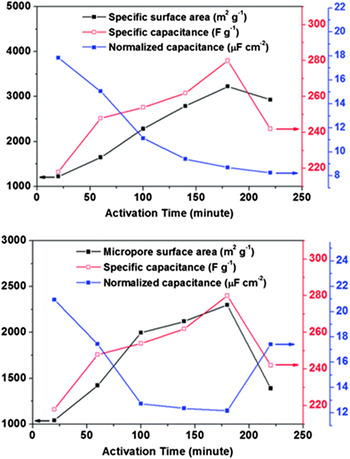
AC is a popular and most considerable research material as electrode for EC and/or battery due to its high specific surface area, high electronic conductivity, and low cost. A surface area of 2000 m2/g can be achieved by controlling distribution of pores during the activation process. Theoretically, the larger the specific surface area of an AC, the greater the C sp is. However, in practice, the condition is more complex, in which smaller surface area of some AC gives a greater C sp than those with a high surface area (Fig. 1).Reference Jin, Yan, Yu and Zhao36
The effect of surface area and activation time to the specific capacitance of AC (reprinted from Ref. Reference Jin, Yan, Yu and Zhao36, with permission from Royal Society of Chemistry).

The C sp can be varied over a wide range of 40–220 F/g, depending on the process applied and the type of electrolyte used.Reference Zhang, Li, Liu, Sun, Mérel and Désilets37,Reference Yu, Chen, Zheng, Zhao, Li and Xu38 Yu et al.Reference Yu, Chen, Zheng, Zhao, Li and Xu38 studied the effects of AC surface group and morphology structure on the electrochemical performance of supercapacitor. In the paper, there were two types of surface functional groups, which had battery-like and supercapacitor-like behaviors, respectively, exposed.
According to Xu et al.,Reference Xu, Wu, Chen, Zhang, Cao and Yang39 fabrication of AC fiber cloth electrodes gives a good cycle stability and high value of the electrochemical double layer capacitor (EDLC) capacitance using carbon dioxide activation. The C sp of 168 F/g for the electrochemical configuration tested in aqueous solution was achieved at temperature of 900 °C. But, the higher C sp of 208 F/g was achieved at the lower temperature treatment (∼600 °C).
B. Graphene
Graphene is generally formed from one atom sheet of graphite with the arrangement of atoms in a regular hexagonal pattern. The two-dimensional carbon material structure of graphene is considered as one of good carbon materials for the supercapacitor application due to its good electronic conductivity, superior mechanical properties, excellent chemical stability, and enhanced charging and discharging.Reference Yan, Liu, Fan, Wei and Zhang40,Reference Liu, Yu, Neff, Zhamu and Jang41 The graphene with a surface area of 2630 m2/g can theoretically perform to a capacitor with 550 F/g.
Yan et al. fabricated graphene as electrode materials in high performance EDLC. It was confirmed that the folding of the graphene can reduce the agglomeration and stacking, which results in improved specific surface area. A high C sp of 349 F/g was achieved from electrode tested in 6 M KOH solution at a scan rate of 2 mV/s. Then, the C sp of the electrode was 8% increased after 5000 cycles—an evidence of good electrochemical stability.Reference Yan, Liu, Fan, Wei and Zhang40
Liu et al. investigated graphene based EC at room temperature and 80 °C with a specific energy density of 85.6 and 136 Wh/kg, respectively, at a current density of 1 A/g, which is equivalent to that of nickel metal hydride battery. The curved graphene can reduce the agglomeration and restacking, thus make full consumption of the C sp and specific surface area.Reference Liu, Yu, Neff, Zhamu and Jang41
C. Carbon black
Carbon black is usually produced by the thermal decomposition of hydrocarbon or partial combustion (basically gases, distillates, and oils) in the gas phase.Reference Taylor, Marsh, Heintz and Rodriguez-Reinoso42,Reference Donnet, Bansal and Wang43 The particular properties of carbon black are considered to be surface chemistry, porosity, structure (aggregate size), and fineness (primary particle size). Typically, the conductivity of carbon black is in the range of 10−1 to 102 1/Ω cm and it is controlled by the capability of electron to cross the gap between graphitic conduction by touching aggregates and by closely spaced aggregates (electron tunneling).Reference Donnet, Bansal and Wang43 The surface area of carbon black has generally covered a wide range, which is from 10 to 1500 m2/g.Reference Kinoshita44,Reference Taberna, Simon and Fauvarque45 Hence, the porosity in carbon black also differs from small surface pore to the definite hollowing out of particles. In addition, the surface area of carbon black is typically considered more accessible for ion transportation than other structures of large surface area carbon.Reference Taberna, Simon and Fauvarque45
The fabrication of high surface area carbon black, containing a binder, has been investigated by Beck et al.Reference Beck, Dolata, Grivei and Probst19 on the EC electrodes with a C sp of 250 F/g by using an aqueous electrolyte with the specific areas ranging from 28 to 1690 m2/g. However, Nasibi et al. applied mechanical pressing technique to fabricate carbon black electrodes. This technique homogeneously mixed carbon black with 10 wt% of polytetrafluoroethylene (PTFE) which acts as a binder in ethanol to produce a slurry and then presses on the Ni foil. The C sp of 33.58 F/g was achieved in 2 M KCl electrolyte.Reference Nasibi, Rashed and Golozar46
Another excellent performance of carbon black was reported by Gnanamuthu et al. in Li-ion battery. The fabrication starts with the mixing of Super P carbon black powder and polyvinylidene difluoride (PVDF) (as a binder) in n-methyl-2-pyrrolidone solvent to form a paste. Then, the paste has been spread onto the copper foil using the doctor blade method. The discharge capacity reached up to 1256 mAh/g in organic electrolyte.Reference Gnanamuthu and Lee47
D. Carbon nanotubes
CNTs are typically produced by the catalytic decomposition of hydrocarbons. By carefully controlling various processing parameters, it is possible to engineer the nanostructures in miscellaneous conformations and control their crystalline order.Reference Azam, Mohamed, Shikoh and Fujiwara48 There is considerable attention on the application of CNTs as electrode materials for EC and other energy storage devices.Reference Hu, Wang, Wang, Zhu and Li49–Reference An, Kim, Park, Moon, Bae, Lim, Lee and Lee53 Compared to other carbon materials, CNT is very good for EC and/or battery due to their unique properties,Reference Zhu, Weber, Yang, Konuma, Starke, Kern and Bittner54,Reference Sakamoto and Dunn55 such as highly accessible surface area,Reference Guittet, Aria and Gharib56 electrical charge storage ability,Reference Azam, Isomura, Fujiwara and Shimoda57 low mass density,Reference Du and Pan58 great chemical stability,Reference Du, Yeh and Pan59 interconnected network structure,Reference Azam, Talib, Mohamad, Kasim and Rashid60 and excellent electrical conductivity.Reference Mohamed, Azam, Shikoh and Fujiwara61 Fabrication of single-walled CNTs (SWCNTs) and multiwalled CNTs (MWCNTs) as electrode materials has been actively investigated in both aqueous and non-aqueous electrolytes.
The C sp of CNTs published by Frackowiak et al. was discussed to be highly dependent on their purity and morphology structure.Reference Frackowiak, Jurewicz, Szostak, Delpeux and Beguin20 For purified MWCNTs, the C sp changes generally from 15 to 80 F/g with surface area ranging from ∼120 to 400 m2/g. The surface area of MWCNT is mostly mesoporous and is assorted with the outer of the tubes, with such cavity come from the entangled MWCNT. Also, C sp can be increased up to ∼130 F/g by applying acid treatment, such as nitric and sulfuric acid. This simple process modifies the surface structure of the MWCNTs and thus introduces the additional functional group, for a storage contribution from pseudocapacitance.Reference Frackowiak, Delpeux, Jurewicz, Szostak, Cazorla-Amoros and Beguin62–Reference Frackowiak, Metenier, Bertagna and Beguin64
Meanwhile, Hu et al. presented a flexible SWCNT supercapacitor; in which the electrode fabrication was done using wire wound root coating technique and then integrated into the commercial paper of single sheets.Reference Hu, Wu and Cui65 The C sp and high specific power of 33 F/g and 250 kW/kg, respectively, were obtained with 1 M lithium hexafluorophosphate (LiPF6) in ethylene carbonate and diethylene carbonate (1:1 v/v) electrolyte. By using the same CNT thin film electrode fabrication technique, Hu et al. integrated the silver nanowire and SWCNTs together, purposely to reduce the sheet resistance of the electrodes.Reference Hu, Choi, Yang, Jeong, La Mantia, Cui and Cui66 This technique provides a device in sulfuric acid electrolyte with a C sp of 200 F/g, a specific power of 200 kW/kg, a specific energy of 30–47 Wh/kg, and stable cycling life over 40,000 cycles. The flexible paper fabricated with SWCNT has great potential to replace current collector in Li-ion battery, due to the advantages of high conductivity, light weight, and low cost.
III. ELECTROPHORETIC DEPOSITION (EPD) TECHNIQUE
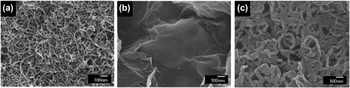
EPD technique is attractive for coatings and advanced processing ceramic materials with a variety of novel applications in the biomedical, electronic, catalytic, and electrochemical fields.Reference Affoune, Prasad, Sato and Enoki67–Reference Holgado, Garcia-Santamaria, Blanco, Ibisate, Cintas, Miguez, Serna, Molpeceres and Requena69 This technique is not only limited in research level but also in the industrial sector. EPD is good due to its low cost, by only requiring simple apparatus, the feasibility to produce uniformity deposition, and fabrication of nanostructured with high purity deposit as well. It is well known that EPD is the best technique for the material surface modification and the polycrystalline patterned film deposition with controlled crystalline texture, well mixed composites and multicomponent films as reported by Shi et al. (Fig. 2).Reference Shi and Zhitomirsky70–Reference Besra and Liu73
Field emission scanning electron microscope (FESEM) images of (a) MWCNT (b) graphene and (c) Ppy films prepared by EPD technique (reprinted from Ref. Reference Shi and Zhitomirsky70, with permission from Elsevier).

EPD technique was discovered in 1808, by the Russian scientist Ruess. It was all started from the phenomenon that an electric field induced the transfer of clay particles in water. EPD technique was first practically applied to deposit particles on the platinum substrate as an emitter in the electron tube.Reference Sarkar and Nicholson74 Hamaker and Zhitomirsky were among the pioneer scientists who investigated the EPD technique in the advanced ceramics field.Reference Hamaker75,Reference Zhitomirsky and Petric76
EPD technique is achieved through the charged particle movement in the suspensions to form particle coagulation and deposition onto substrate under an applied electric field. Meanwhile, the preparation of stable suspension is very important to effectively apply this technique, where the colloidal particles are free to move. The high electrophoretic mobility and electrostatic repulsion of inorganic particles in the suspension are essential for good dispersion. The movement of particles should be lowered at the substrate surface to facilitate the process of deposition.
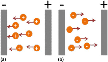
On comparison with other advanced deposition techniques, EPD process is quite versatile and flexible because it could be easily handled for a specific application. Particularly, by controlling the applied voltage and deposition time, the thickness and mass might be readily changed though EPD is a wet process. There are two types of EPD processes (Fig. 3) depending on which electrode the deposition occurs. When the particles are positively charged, the deposition will occur on the cathode under the applied electric field and this process is known as the cathodic EPD process [Fig. 3(a)]. In despite the fact that the deposition of negatively charged particles occurs at the anode, the process is called the anodic EPD process [Fig. 3(b)].
Schematic illustration of EPD process. (a) cathodic EPD and (b) anodic EPD.

With suitable modification of particle surface charge, two types of EPDs can be realized. However, for anodic EPD process related to the oxidation and dissolution of the metallic substrate, one problem occurs when aqueous suspension is used, which makes the process of particle deposition become difficult. Hence, the cathodic EPD process is frequently used.
A. Deposition kinetics and mechanism
The EPD technique was successfully developed in numerous applications, however the precise mechanism that could entirely explain the trend of the deposition on the substrate is not well understood.Reference Van der Biest and Vandeperre77 There are four principle mechanisms; the flocculation by particle deposition, the neutralization of particle charge, the electrochemical particle coagulation, and the electrical double layer distortion.Reference Shi and Zhitomirsky70,Reference Boccaccini and Zhitomirsky72,Reference Besra and Liu73,Reference Van der Biest and Vandeperre77,Reference Fukada, Nagarajan, Mekky, Bao, Kim and Nicholson78 Bouyer et al. suggested that EPD has a two-step process, which comprised the transfer of charged particle to the oppositely charged electrode and the particle coagulation and deposited on the electrode surface to form a mass deposit.Reference Bouyer and Foissy79
HamakerReference Hamaker75 and Zhitomirsky and PetricReference Zhitomirsky and Petric76 discussed that the stable suspension is an important basis for the excellent formation of the deposition by EPD technique. The formation of the deposition by EPD technique was related with the formation of the sediment by gravitation. This mechanism is called flocculation by particle accumulation. Grillon et al. suggested the neutralization of particle charge mechanism, which exhibited that the charged particles might be neutralized when they come in contact with the electrode and then became static. However, this mechanism is possible for the particle and monolayer deposition.Reference Grillon, Fayeulle and Jeandin80
IV. ENERGY STORAGE DEVICE
Electrical energy can be stored in two fundamentally different devices; (i) in batteries, as capability available chemical energy that involves Faradaic reduction and oxidation to discharges when both electrodes, anode and cathode, are existent and (ii) in supercapacitors, the positive and negative electrical charges that exist at the interface between the electrolyte and electrode. This ion transfer process is also known as non-Faradaic electrical storage.Reference Conway81
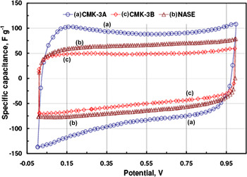
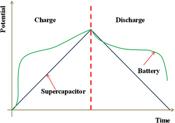
For batteries, the chemical interchange between the materials on the anode and cathode should take place. This process comprises a phase change of electrode materials, which will limit the cycle life of one to several thousand charge and discharge cycles.Reference Conway81 For supercapacitors, only a lack and addition of electrical charges have to be stored on each current collector, and no phase or chemical changes are involved. In theory, the storage of electrical charges by this process will have an unlimited cyclability. The main difference between batteries and ECs is that the charge and discharge processes of ECs are virtually mirror images of each other, in despite, those processes for batteries being infrequently the same. The rectangular shaped cyclic voltammetry (CV) of different carbons for EC confirms capacitance behavior and good reversibility, which is shown in Fig. 4. Another distinctive characteristic between batteries and ECs during the charge and discharge is shown in Fig. 5. However, the potential difference of ECs is changing with the amount of charge stored.
CV curves of different carbon EC.Reference Lufrano and Staiti82

The relationship between charge and discharge of batteries and capacitors.

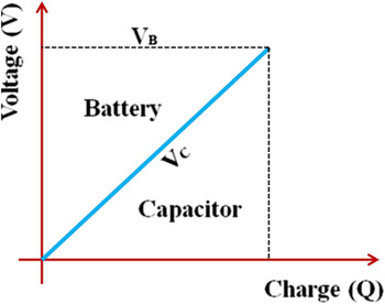
On the other hand, the major significance of the energy density dissimilarity between batteries and supercapacitors can be understood by Fig. 6. The line V B is the fixed voltage of a battery cell, while the total charge, Q, is stored; as the line V C is the linear voltage across a supercapacitor device which is charged to the charge, Q. The essential VQ under line V B and V C relates to the energy for the batteries and supercapacitors, respectively. The energy charging of the supercapacitor is half of the energy charging of the battery to a terminal voltage V B with charge, Q. Hence, the total energy, E, of a battery can be stored is the product of charge, Q, and the potential difference, V, and is shown in the following equation:
 $$E = QV\quad .$$
The difference of energy stored by a battery and capacitor.

The total energy, E stored by a supercapacitor should be 1/2 QV, whereas can be expressed as 1/2 CV 2, due to the equation of Q = CV. In addition, the total power, P of a supercapacitor device is shown in the following equation:
 $$P = {{{V^2}} \mathord{\left/ {\vphantom {{{V^2}} {4{\rm{ESR}}\quad {\rm{,}}}}} \right. \kern-\nulldelimiterspace} {4{\rm{ESR}}\quad {\rm{,}}}}$$
where ESR is the equivalent series resistance (ESR).Reference Conway, Birss and Wojtowicz83
A. Energy storage mechanism
EC can be divided into two categories, EDLC and pseudocapacitor, due to their different charge storage mechanisms.Reference Conway81,Reference Conway, Birss and Wojtowicz83,Reference Qu and Shi84 The Faradaic reactivity of the surface functional group, tending to EDLC, will possibly demonstrate 1–5% of pseudocapacitance out of its total capacitance, whereas is generated by the pretreatment or preparation process of the electrode carbon materials. The pseudocapacitors typically show 5–10% of electrostatic double-layer capacitance, because of the proportionality of the electrochemically accessible interface area.
B. Electrochemical double-layer capacitor
An EDLC develops non-Faradaic capacitance evolving from the electrostatic charge stored at the double-layer, and the ion transfer access has to be confirmed on the charge and discharge processes. Effectiveness of the EDLC, no composition or chemical phase changes are required in the charging and discharging processes; therefore, EDLC possesses unlimited cyclability and is highly reversible without significant degradation. The double-layer capacitance can be determined by using the following equationReference Lufrano and Staiti82:
 $$C = {{A\varepsilon } \mathord{\left/ {\vphantom {{A\varepsilon } {4\pi d}}} \right. \kern-\nulldelimiterspace} {4\pi d}}\quad ,$$
where A represents the surface area of the electrode, ε represents the electrolyte dielectric constant, and d represents the thickness of the double-layer. The charge stored is transferred across the double-layer, which includes a Helmholtz layer with the thickness range of 0.5–0.6 nm, corresponding to the diameters of the solvent ions staying inside it, and an extensive region of diffusion layer with dimensions of 1–100 nm, relying on the concentration of the electrolyte.Reference Qu and Shi84
Shih et al. explained that CNT possessed excellent chemical stability and good conductivity when directly grown onto graphene film as one electrode for EDLC. The formation of bundle arrays offered a higher surface area to perform with electrolyte. Thus, resulting in higher C sp of 128.4 F/g.Reference Shih, Lee and Huang85 Furthermore, Fang et al. successfully fabricated MWCNT/α-MnOOH films by EPD technique. The films with a low mass loading and high areal capacitance of 0.05 mg/cm2 and 0.2 F/cm2, respectively, were obtained. Electrochemical measurement show that the films perform high Csp of 327 F/g in 0.1 M Na2SO4 aqueous solution.Reference Fang, Zhang, Wu, Liu, Wen, Du and Jiang86
C. Pseudocapacitors
In contrast to the mechanism of EDLC, pseudocapacitor ideally stores charge faradaically via the charge transfer between the electrode and electrolyte. This is realized due to the reduction–oxidation reactions, intercalation processes, and electrosorption. The pseudocapacitor may perform higher energy densities and capacitance properties than EDLC through the presence of Faradaic processes.Reference Dubal, Lee, Kim, Kim and Lokhande87 Metal oxides and conducting polymers generally are the two different electrode materials used to store charge in pseudocapacitor. A pseudocapacitor consists of reduction–oxidation (redox) reactions during charging process, which occur at different electrodes. Also, during discharging processes, the ion transfer is in the opposite direction through the electrolyte. The charging and discharging processes of a supercapacitor are much faster than a battery because of the faradaic energy accumulation with faster redox reactions.Reference Wei, Nagarajan and Zhitomirsky25
Chen et al. reported that excellent pseudocapacitor electrode of MWCNT/manganese oxide (MnO) successfully deposited by EPD technique. The MWCNT/MnO films presented a porous structure with some rupture MnO particles incorporated and acquired a high surface area for the redox reactions, resulting the high C sp of 260 F/g.Reference Chen, Chien, Chan, Lin and Wang88 Meanwhile, Ghasemi et al. investigated that the graphene was deposited onto stainless steel as a conductive substrate via EPD technique. Then, hybrid nickel–cobalt hexacyanofarrate nanoparticles were deposited on the graphene electrode using bipotential method. The films indicate the higher Csp of 411 F/g.Reference Ghasemi, Ojani and Ausi89
V. CRITICAL FACTORS THAT INFLUENCE CHARGE STORAGE PERFORMANCE
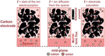
For conventional capacitor, the capacitance value is basically tens of Faradays per gram of the electrode materials, in which two dimensional planar electrodes only have a small specific surface area, and ion diffusion could be present for such planar electrodes. This limitation could be reduced by having a high surface area of porous electrodes, and three dimensional planar electrodes are used. The high surface area of porous electrodes and three-dimensional planar of electrodes could be performed via activation process. In Fig. 7, the schematic view of the ion movement into the porous carbon electrode is shown. The size of micropores are less than 2 nm, mesopores are ranging from 2 to 50 nm and macropores are greater 50 nm, whereas they are randomly produced in AC.
Schematic of ion movement through the porous carbon electrode (reprinted from Ref. Reference Porada, Borchardt, Oschartz, Bryjak, Achitson, Keesman, Kaskel, Biesheuvel and Presser90, with permission from Royal Society of Chemistry).

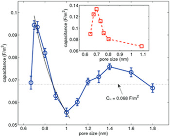
According to Conway,Reference Conway81 it is only the mesopore which constructs the major contribution to the capacitance, in despite the micropore, which influences most of the surface area, producing only a small contribution because the electrolyte ions could not access. However, Feng et al. reported that there would be an irregular increase in the capacitance at pore size less than 1 nm. If the pore size was decreased, the capacitance also decreased because the Helmholtz layer was altered and the surface area for the double-layer formation was reduced (Fig. 8). When the pore size is rapidly decreased to less than 1 nm and is proportional to the size of the salvation shell, the ions will be highly charged. This explains the fact that the ion center could move closer to the electrode surface, resulting in enhanced capacitance.Reference Bao, He, Liang, Zhou and Li91,Reference Feng and Cummings92
Relationship between pore size and capacitance value (reprinted from Ref. Reference Bao, He, Liang, Zhou and Li91, with permission from American Chemical Society).

EPD is an excellent technique for consistently producing uniform SWCNT nanoporous network on stainless steel substrate. The size of SWCNT produced from EPD technique was found to be around 1 nm and unaffected even by extending the processing time of EPD. Electrochemical analysis using 1 M H2SO4 electrolyte was performed by using CV measurement and obtained the capacitance value of 26.5 mF/cm2.Reference Moore, Kang and Wen93
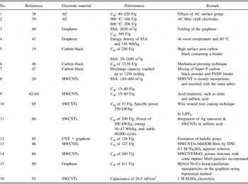
In total, all carbon materials being used as electrode and their storage performance are summarized in Table I.
Carbon based active material and their performance in energy storage device.

SSA = Specific surface area.
VI. COST ASSESSMENT
The markets for ECs have developed in terms of large devices (>100 F) and smaller devices (<10 F). The fastest growing of the EC market, with 12% and US$400 million of global growth rate and revenue, respectively, was reported in 2014. The market was expected to grow up to 27% and US$1100 million of global growth rate and revenue, respectively, in 2019. The manufacturing cost of products is closely fixed to volume; the cost decreases quickly with the increased volume up to comparatively high production rates. Potential market sales of ECs are in the many millions of units per year, therefore, the automated production facilities are required to reduce the unit costs, in which the large markets can be expanded.
The cost to manufacture EC relies on the material and production costs. Lately, costs of the material are high. The cost of carbon for use in ECs can be as high as US$100/kg, with the average price in the range of US$30–50/kg. The electrolyte cost is also expensive being in the range of US$5–10/L for both acetonitrile and propylene carbonate.Reference Gualous, Gallay, Alcicek, Ighil and Oukaour94,Reference Hahn, Kotz, Gallay and Siggel95 Reducing the highest maintenance and operation cost, with more automated production is one of the methods that should be considered. Otherwise, production of carbon based on using waste material and changing electrolyte to aqueous solution can reduce material cost effectively.
VII. DESIGN CONSIDERATION
In producing high performance EC with low fabrication cost, the design consideration of the EC cell must be at the top priority. It's not only about the consumer satisfaction, but also can reduce the toxicity of material with regard to the safety concerns and quality standard. There are a few items to consider in design consideration.
A. Temperature effects and thermal properties
For the minimum performance effect over the lifetime of the application, it is required to maintain the supercapacitor core temperature within the rated range of temperature of the device. The lower the temperature is retained, the better for lifetime considerations. Suggesting that, the supercapacitor must be provided with an electrically insulating shrink folder around the body. This is thus the most effective for cooling of the supercapacitor.Reference Hahn, Barbieri, Gallay and Kotz96
B. Lifetime
The life of a supercapacitor is mostly influenced by a combination of operating temperature and voltage. When considering the supercapacitor life, the data sheets show the change in performance, which is the increase in resistance and decrease in capacitance. The supercapacitor's life will not end, however the performance will slightly degrade upon the excess usage of it.Reference Kotz, Ruch and Cericola97
C. Frequency response
Supercapacitor has a standard time of ∼1 s. One time constant gives the time required for 63.2–36.8% full charge or discharge of a supercapacitor. The time constant of a supercapacitor is more higher than that of an electrolytic supercapacitor. Consequently, it is not possible to expose supercapacitor to a continuous moving current as overheating may result. The supercapacitor can react to short pulse power demands, however, the efficiency is reduced due to the time constant.
D. Charging
The charge/discharge of the supercapacitor that can happen at the same time due to the energy storage mechanism is not a chemical reaction. Hence, the rated current for the supercapacitor is utilized for both charge and discharge. Practically, the efficiency of charge/discharge is the same. There are many types of methods that are possible for charging of the supercapacitors, such as through constant current or power charging by using direct current or alternate current source.
E. Efficiency
Dissimilar with batteries, the supercapacitors have the same efficiency through charge/discharge. This allows the supercapacitor to be quickly recharged without current restrictive as long as the current is in the rated current for the supercapacitor. The only efficiency losses related with supercapacitor are due to the internal resistance of the device during cycling, resulting in IR drop. Mostly, the uses of the supercapacitor are 98% and exceed of the efficiency. The efficiency is reduced when using high power or current pulse, but is still greater than 90%.Reference Hahn, Kotz, Gallay and Siggel95,Reference Kotz, Ruch and Cericola97
VIII. SUMMARY
Carbon materials have remarkable properties like excellent ion accessibilities and high surface area that made them to be selected as electrode material for batteries and ECs. The main factors that imposed the selection of carbon materials as electrode are as follows; pore geometry, wettability, developed surface area, presence of electroactive species, and conductivity. For example, the micropores contribute in the charge storage processes and thus the existence of mesopores, carbon materials can provide a high energy at a high rate. In consideration of specific surface area, CNTs are more capable for storing of electrical charges. This is attributed to the accessible mesopores developed by the central canal and entanglement.
On the other hand, there are many techniques to deposit carbon materials, and the formation and operation are highly depending on the precursors used and processing parameter. The EPD technique can perform with excellent uniformity of film, film thickness and deposition rate; possibility of film formation of large surface area. In addition, EPD technique can directly prepare the electrode without incorporation of precursor gases, thus reducing the process time, complexity, and cost.
Finally, this review revels new potential commercial applications; from power back-up system to hybrid formation for electric vehicle, and also for lighting and ignition in normal combustion engine powered vehicles.
ACKNOWLEDGMENT
The authors would like to acknowledge the Ministry of Education Malaysia for the financial support through MyPhD program.