Introduction
Fiber-reinforced polymer composites (FRPCs) are used in aerospace, automotive, and sports industries because of their high specific strength and stiffness, combined with design flexibility and light weight [Reference Tehrani, Boroujeni, Hartman, Haugh, Case and Al-Haik1, Reference Kandare, Khatibi, Yoo, Wang, Ma and Olivier2]. Among various reinforcing fibers, carbon fibers (CFs) are extensively attractive in these industries because of their superior specific strength and stiffness, low density and reasonable cost [Reference Cai and Aref3, Reference Lou, Lopes and Lopes4]. However, the behavior of FRPCs are highly dependent and controlled by the properties of their constituent parts [Reference Shahid, Villate and Barron5]. Also, the performance of FRPCs under different loading conditions (i.e., axial, transverse, impact, and torsional) and thermal stability at elevated temperatures are very critical for reliable applications. Among these FRPCs, the use of carbon fiber composites (CFCs) is further limited because of factors such as low transverse load-bearing capacity, poor resistance to crack propagation, and delamination [Reference Song, Li, Qi, Li, Lu and Zhang6, Reference Boroujeni, Tehrani, Nelson and Al-Haik7]. In recent years, researchers have used various methods to enhance these mechanical and thermal properties of CFCs. Among them, addition of nanoparticles has been proven to be the most promising method to tailor the overall mechanical and thermal performance of CFCs [Reference Kim, Rhee, Lee, Hui and Lau8, Reference Siddiqui, Woo, Kim, Leung and Munir9, Reference Uddin and Sun10].
Addition of functionalized nanoparticles in CFCs has been reported to significantly increase the fiber–matrix interfacial bonding [Reference Kim, Park, Okoli and Zhang11, Reference Bekyarova, Thostenson, Yu, Kim, Gao and Tang12, Reference Jony, Thapa, Mulani and Roy13]. FRPCs without any nano-reinforcement show mechanical performance only in one direction (in the direction of fiber), and that in the transverse direction are weaker because of poor interfacial bonding between the fiber and matrix. Existence of nanoscale particles, along with continuous fibers, oriented in different directions in the matrix provides FRPCs both in-plane (i.e., x and y direction) and out-of-plane (z direction) performance [Reference Gabr, Okumura, Ueda, Kuriyama, Uzawa and Kimpara14, Reference Hasan, Zainuddin, Tanthongsack, Hosur and Allen15, Reference Rahman, Rahman, Ashraf, Muneer and Rashed16, Reference Hossain, Possart and Steinmann17]. For these reasons, addition of very small amounts of nanofiller significantly contributes to enhance engineering performance of FRPCs [Reference Chatterjee, Nafezarefi, Tai, Schlagenhauf, Nüesch and Chu18].
Among the nanofillers, montmorillonites nanoclay (MMT) was widely used because of ease in dispersion besides low cost and effective reinforcement properties [Reference Sinha Ray and Okamoto19, Reference LeBaron, Wang and Pinnavaia20, Reference Alexandre and Dubois21]. Zhou et al. [Reference Zhou, Hosur, Jeelani and Mallick22]. reported increased tensile strength (5%) and modulus (2%) by adding 2% MMT (unmodified) in CFCs. Chowdhury et al. [Reference Chowdhury, Hosur and Jeelani23]. also found improved flexural and thermomechanical properties at 2 wt% nanoclay loading. Improvement in these properties was attributed to better fiber–matrix interaction and improved interfacial bonding achieved through the incorporation of MMT nanoparticles.
Another most prominent nanofiller is graphene nano platelets (GnPs) which are the strongest materials ever tested in the world [Reference Lee, Wei, Kysar and Hone24]. GnPs are graphene layers stacked together in a platelet morphology. The ultrahigh aspect ratio of GnPs [600–10,000] increases the contact area with matrix and maximizes stress transfer from polymer to nanofiller [Reference Li and Kim25]. However, dispersion of GnPs in the polymer matrix is very challenging because of strong Van der Waals forces and strong π–π interactions between platelets that tend to reagglomerate them even after dispersion [Reference Si and Samulski26, Reference Si and Samulski27]. Significant research has been carried out to investigate the properties of epoxy–GnPs composites; however, the effect of GnPs on the mechanical and thermomechanical properties of fiber-reinforced composites is not well studied, and to the best of our knowledge the data available in the open literature are very scarce [Reference Cho, Chen and Daniel28, Reference Li, Zhang, Huang, Bilotti and Peijs29, Reference Moriche, Sánchez, Jiménez-Suárez, Prolongo and Ureña30].
Also in recent years, researchers are investigating the effect of binary nanoparticles i.e., MWCNT with GnPs, CNTs with carbon black, and graphene oxide with CNTs [Reference Yang, Lin, Huang, Tien, Wang and Ma31, Reference Sumfleth, Adroher and Schulte32, Reference Jyoti, Dhakate and Singh33, Reference Tcherbi-Narteh, Nuruddin, Hosur, Gupta, Lattimore and Jeelani34]. Most of these studies reported reduction in mechanical and thermal properties over the neat counterpart. The reduction in these properties due to addition of binary nanoparticles was attributed to the difficulty in achieving uniform dispersion and rise in viscosity of polymer.
The aim of this study was therefore to perform a comprehensive investigation of CFCs’ transverse mechanical and viscoelastic properties by reinforcing (i) MMT, (ii) GnPs, and (iii) both MMT and GnPs (binary) nanoparticles. Most of the literature reported best performance for 2% MMT, and the same percentage of MMT has been used for the study. For GnPs, minimum percentage was considered to be studied and 0.1% was chosen to investigate, since most of the literature reported promising enhancement in lower GnPs loading [Reference Rafiee, Rafiee, Wang, Song, Yu and Koratkar35, Reference Zhao, Zhang, Chen and Lu36]. To achieve good dispersion of the nanofillers in matrix, the most effective combination of dispersion techniques was used [Reference Li, Zhang, Huang, Bilotti and Peijs29, Reference Moriche, Sánchez, Jiménez-Suárez, Prolongo and Ureña30, Reference Zabihi, Ahmadi, Nikafshar, Chandrakumar Preyeswary and Naebe37]. Also, we investigated and briefly described the effect of individual/binary MMT and GnP reinforcement on the microstructural features and the damage mode of the CFCs corresponding to the mechanical result obtained.
Results and discussion
Flexural test
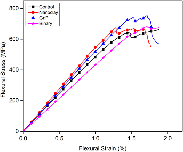
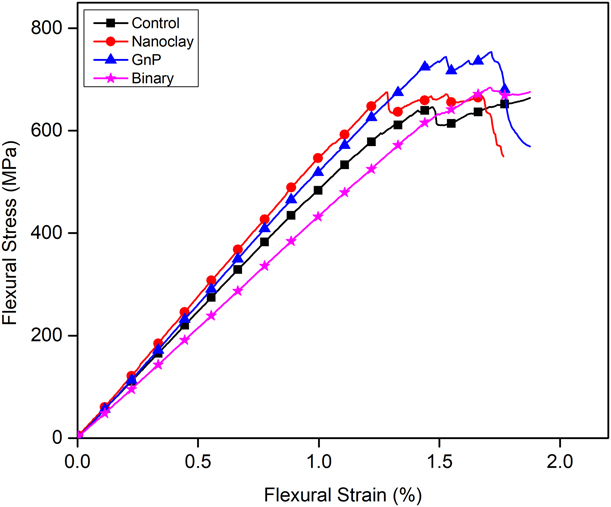
Figure 1 represents the typical flexural stress–strain (S–S) response of the CFC samples. All of the samples showed linear patterns with a steep rise in stress up to yield, followed by nonlinear response with a decreasing slope up to the maximum flexural stress. The reason for the nonlinear portion is the initiation of microcracks at the fiber–matrix interface that make the load-bearing capacity of the composite fluctuate. However, the interfacial bonding and overall internal structure are still strong enough to absorb a load up to a maximum point. After the maximum stress point, a relative sudden fall in the stress–strain curve was observed in individual nanoclay- and GnP-added samples compared with the control counterpart. This indicates that after the maximum stress point, fiber breakage is more dominating in nanoparticle-added CFCs that causes an abrupt decline in strength, whereas for the control sample, cracking and delamination are more dominating which causes a slow decline. This is because of the improved interfacial bonding achieved by the addition of nanoparticles, resulting fiber–matrix debonding and delamination more difficult, and hence, the ultimate failure in these samples occurred because of fiber breakage.
Stress–strain response of the control and nanoparticles added CFCs in the flexure test.
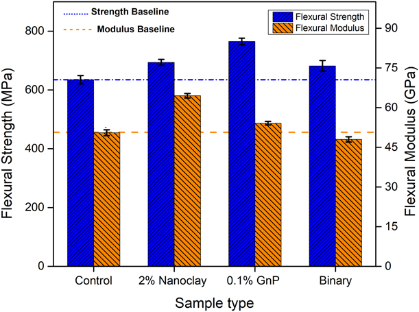
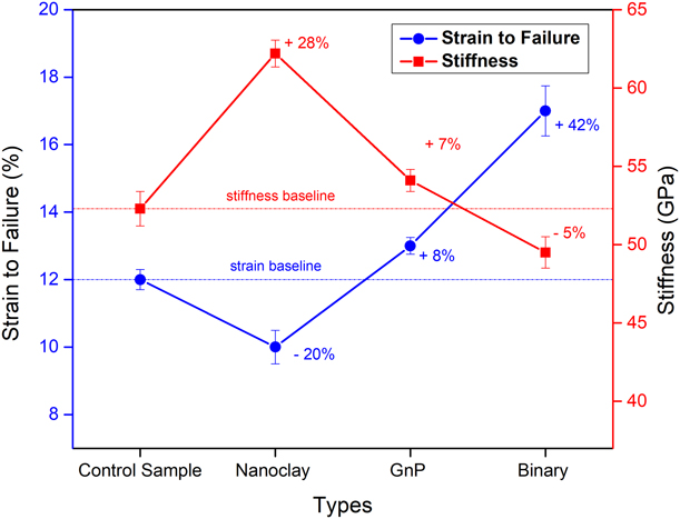
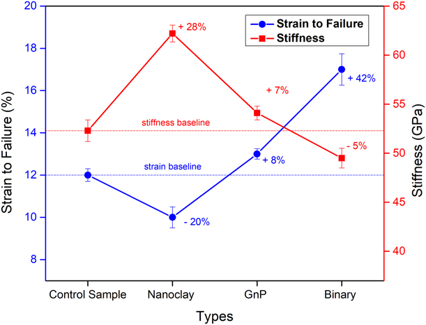
It can be seen from Fig. 2 and Table I that individual nanoclay- and GnP-added CFCs showed increased flexural strength and modulus compared with the control samples. Nanoclay-added CFCs exhibited 28% higher flexural modulus (64.5 GPa) than the control samples (50.5 GPa), that is, the highest improvement in flexural modulus among all types. By contrast, although GnP-added samples showed little improvement (7% than the control samples) in flexural modulus, these samples showed highest flexural strength of 765 MPa, that is, 21% higher than the control samples (635 MPa). These results indicate that nanoclay is more effective to increase the stiffness of the CFCs, and GnPs are comparatively more effective to achieve higher strength of the CFCs. However, the changes in flexural strength in binary nanoparticle-added CFCs were not much significant. In contrast to the individual nanoparticles, these samples showed reduced stiffness by 5%, and thus exhibited maximum strain to failure of 17%, whereas control samples showed 12% stain to failure. This indicates that after adding both nanoclay and GnPs at a time, the CFCs became more flexible and exhibit more deformation before failure. Figure 3 is illustrates the changes in stiffness and the respective strain to failure of all types of CFCs.
Changes in flexural strength and modulus on addition of nanoparticles in the CFCs.

Comparative list of the static flexural strength and modulus of the control and nanoparticles added CFCs.

Changes to strain to failure and flexural stiffness on addition of nanoparticles in the CFCs.
Microstructure and fracture analysis
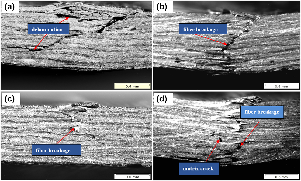
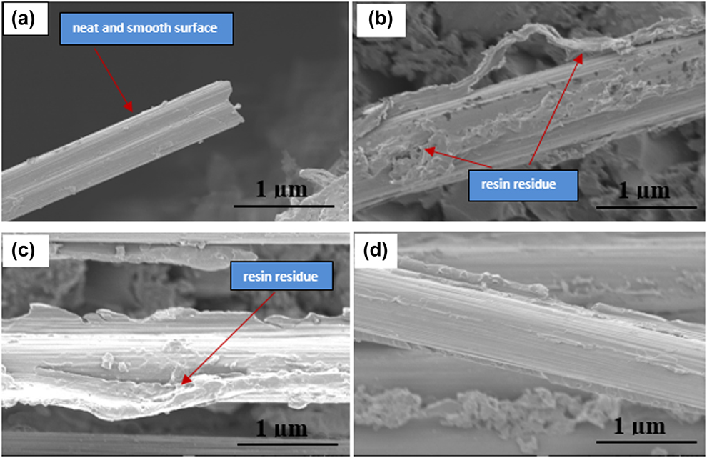
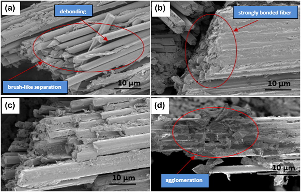
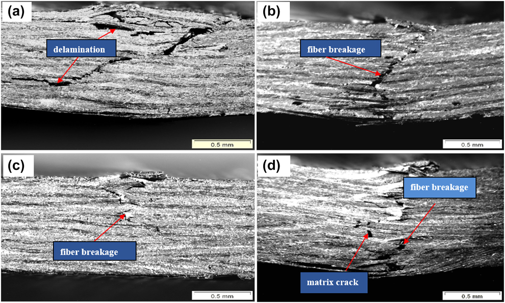
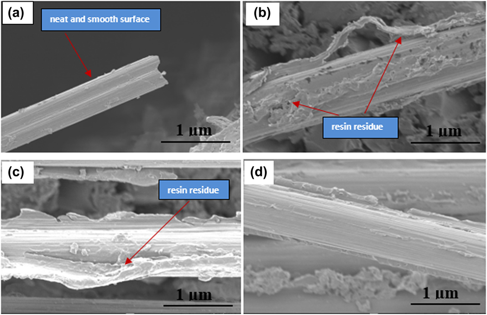
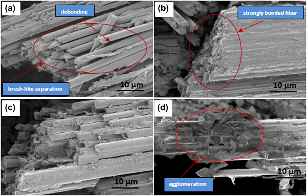
Optical microscopy (OM) and scanning electron microscopy (SEM) images of fractured flexure samples are shown in Figs. 4–7. The OM image of the control sample [Fig. 4(a)] shows a large delaminated area at both compressive and tensile sides of the CFCs. Matrix cracking and fiber were also observed in these specimens. On contrary, fractured specimens of nanoparticle-added CFCs [Figs. 4(b)–4(d)] show a less delaminated area, specially individual nanoparticle-added CFCs [Figs. 4(b) and 4(c)] show almost no delamination. A large delaminated area and severe matrix cracking in fractured control specimens indicate poor fiber–matrix interfacial bonding, and relatively brittle and weaker nature of the matrix. On the other hand, less delaminated areas and matrix cracking in nanoclay- and GnP-added CFCs indicate improved interfacial bonding that may be restricted fiber–matrix debonding, fiber pull-out, and ultimate delamination that is evident from SEM images of ‘protruded single fiber’ and ‘broken fiber bundle’ of fractured specimens, respectively [Figs. 5 and 6]. From Fig. 5, it can be seen that the single fiber surface of the control specimen [Fig. 5(a)] is smooth with no resin residue, whereas by contrast, nanoclay- and GnP-added CFCs [Figs. 5(b)–5(d)] were found to show a considerable amount of resin residue on the surface, even after separation. SEM images of the broken fiber bundle (Fig. 6) of the fractured specimen indicate that the fibers are intact with almost no separation or debonding [Figs. 6(b) and 6(c)], whereas the control CFCs samples show brush-like separated and unbonded smooth fibers [Fig. 6(a)].
Optical microscopic images of the fractured specimen. (a) Control, (b) nanoclay added, (c) GnP added, and (d) binary nanoparticles (nanoclay and GnP) added.
SEM images showing single fiber surfaces of fractured specimens in the flexure test of (a) control, (b) nanoclay added, (c) GnP added, and (d) binary nanoparticles (nanoclay and GnP) added CFCs.
SEM images of fractured fiber bundle in the flexure test of (a) control, (b) nanoclay added, (c) GnPs added, and (d) binary nanoparticles (nanoclay and GnP) added CFCs.
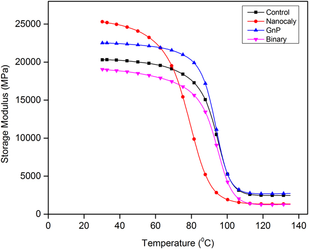
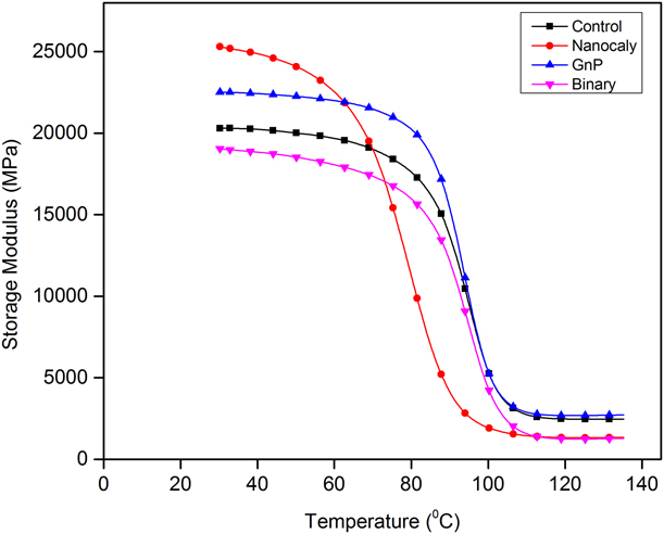
Changes in the storage modulus of the control and nanoparticles added CFCs with response to the temperature.
The reason behind these improvements in interfacial bonding can be attributed to the presence of surface-modified nanoparticles in the epoxy matrix, which highly facilitated fiber–matrix interactions because of their very high aspect ratio, and ensured good fiber–matrix bonding because of active functional groups on nanoparticles’ surface [Reference Peng, Zhou, Zhou and Yao38]. In addition, nanoparticles in the epoxy matrix greatly obstruct polymer chain mobility and increase shear strength of the matrix that allows stress to transfer through friction and increases interfacial bonding in fiber composites. This effect of strong interfacial bonding is found to be more significant for individual GnP-added samples, as they showed highest flexural strength and almost no delamination during fracture [Fig. 4(c)]. This could be attributed to the inherent strongest mechanical properties of GnPs and the presence of active NH2 functional groups on GnPs’ surface that acted effectively to increase interaction. These changes in fiber–matrix bonding and morphology ultimately increased transverse (out-of-plane) properties of the CFCs with good flexural strength and modulus [Reference Zabihi, Ahmadi, Nikafshar, Chandrakumar Preyeswary and Naebe37].
Also, the matrix cracking in individual nanoparticle-added samples were relatively lower than the control counterpart which could be attributed to the toughening effect of matrix due to addition of nanoparticles. Nanoparticles in epoxy resin create considerable cavities and irregular orientation that reduces stress concentration in the crack tip and bifurcates crack propagation in the interfacial layer and bulk matrix, thus increasing the toughness and consequently restricting ultimate matrix cracking [Reference Zabihi, Ahmadi, Nikafshar, Chandrakumar Preyeswary and Naebe37]. This effect is more significant for nanoclay-added samples, as nanoclay interacts with epoxy resin more effectively, both physically and chemically, and creates interlocking structures [Reference Peng, Zhou, Zhou and Yao38]. As a result, nanoclay-added matrices exhibited more rigid behavior which could be attributed to the optimum enhancement in the flexural modulus of nanoclay-added samples (Table I).
However, binary nanoparticle-added samples although showed slightly improved flexural strength (by 7%), the flexural modulus of these sample were considerably reduced (by 5%). Because of reduced stiffness, these samples showed the highest strain to failure of 17% (42% higher than the control), among all types of CFCs (Fig. 3). The optical image of these specimens revealed the delaminated area with fiber–matrix debonding and matrix cracking [Fig. 4(d)]. These observations indicated that addition of two nanoparticles at a time in the epoxy matrix could not significantly change the interfacial properties and matrix morphology of the CFCs. The main reason behind such outcomes might be the poor dispersion of binary nanoparticles in epoxy resin. Typically, it is difficult to disperse two or more types of nanoparticles simultaneously in epoxy resin, ensuring uniform distribution, proper nanoparticle–epoxy interaction, and placing a homogeneous number of particles in between fibers and resin. Challenges that were observed are nanoparticles reagglomeration, volatile entrapment as bubble, and increased viscosity of the resin mixture that might have decreased the fiber wettability, resulting in poor fiber–matrix bonding. The agglomeration of nanofillers in binary nanoparticle-added samples was seen in the SEM image [Fig. 6(d)] of fractured fiber bundle. Agglomerated nanoparticles are stress raisers that act as a crack initiation site, leading to premature failure, thereby reducing matrix and interfacial properties [Reference Chatterjee, Nafezarefi, Tai, Schlagenhauf, Nüesch and Chu18]. Consequently, SEM images of binary nanoparticle-added samples showed poor fiber–matrix bonding, and because of the flexible structure, these samples showed higher deformation.
Again, to get the best properties for the binary system, it is necessary to use the optimal combination of the individual percentage. It also might be the case that individually the nanoparticle shows best performance for the used percentage, although in combined form, their individual effect is suppressed. Therefore, there are open fields to study the properties with different combination of the MMT and GnPs to get the optimal combination for the binary system.
DMA
Figures 7 and 8 and Table II show thermomechanical properties of the control and nanoparticle-added CFCs. The storage modulus represents the stiffness of viscoelastic materials, and at room temperature, it is related to the flexural modulus [Reference Ashori, Menbari and Bahrami39].
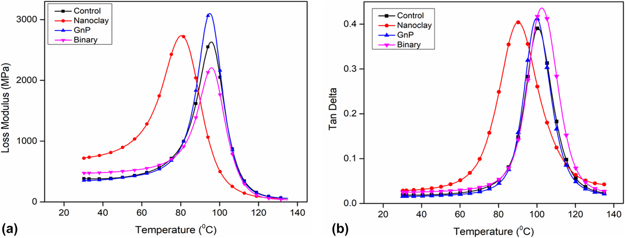
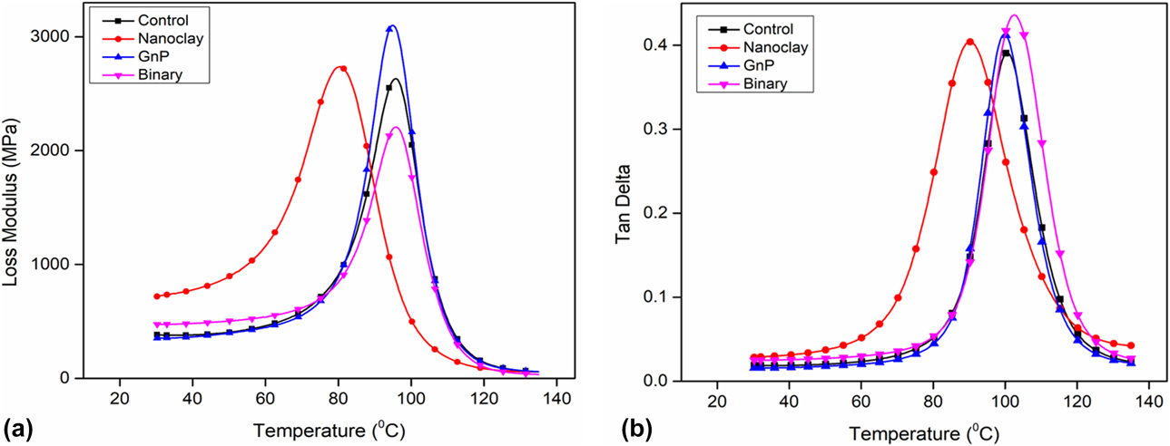
Changes in (a) loss modulus and (b) tan δ with response to temperature.
Comparison of thermomechanical properties of the CFCs.

From Fig. 7, it is seen that both individual nanoclay- and GnP-added CFCs show enhanced storage modulus (24.5% and 11% higher, respectively) compared with the control samples. These changes in the storage modulus on addition of nanoparticles followed the same trends that were observed for the change in the flexural modulus in Table I. The improvement in the storage modulus can be attributed to the mechanical interlocking due to the addition of nanoparticles that restricted polymer chain mobility. As discussed earlier, nanoclay acts more effectively to make the polymer matrix stiffer, and nanoclay-added samples showed the highest storage modulus in dynamic mechanical analysis (DMA) test because of difficult chain mobility in these samples.
With increasing temperature, polymer chain mobility become easier that reduces effective stress transfer between the fiber and matrix of the composite samples. As a result, with increasing temperature, stiffness of the viscoelastic samples gradually decreases, showing fall down in the storage modulus curve. The temperature associated with the sharp drop of the storage modulus refers to the glass transition temperature, T g. From Fig. 7, it is seen that, among all types, this decline in the storage modulus is more abrupt for the nanoclay-added samples, with a comparatively small and unstable operating region (the zone below glass transition temperature, T g). This indicates that with increasing temperature, polymer chain mobility in nanoclay-added samples become comparatively easier and they readily loose stiffness. By contrast, GnP-added samples showed better mechanical stability that is evident from the longer and comparatively flat plateau below T g (Fig. 7). Also, the storage modulus after T g, that is termed as the rubbery plateau was highest for GnP-added samples.
The loss modulus is regarded as the materials’ ability to dissipate energy applied to it. Figure 8(a) represents the changes in the loss modulus on addition of nanoparticles. It is seen that individual nanoparticle-added CFCs samples showed enhanced loss modulus than the control samples. The loss modulus depends on the fiber–matrix interfacial adhesion that facilitates more energy transfer in the form of heat. From Fig. 8(a), it is clear that GnP-added samples showed highest loss modulus (17.8% higher than the control counterpart) among all types. This can be attributed to the improved fiber–matrix interfacial bonding achieved by the addition of GnPs that enhanced shear stress and energy dissipation of these samples, and thus increased the overall loss modulus. Also, the GnP itself being the strongest material with higher heat conductivity, stress and heat transfer between the fiber and matrix in these samples were more effective among all types. This is another primary reason why GnP-added samples showed a comparatively stable storage modulus through the temperature range and highest loss modulus in the DMA test.
Binary nanoparticle-added samples showed inferior property in the case of both storage and loss modulus. The inferior thermomechanical properties in binary nanoparticle-added CFCs can be attributed to the very same reasons that caused lower flexural properties, i.e., poor dispersion and particle agglomeration that reduced overall thermomechanical performance as well. In addition, as discussed earlier, the combination of loading concentration of two nanoparticles in the binary system might not be the optimal to get the best thermomechanical property.
Figure 8(b) shows the change in the tan δ value with temperature for the CFC samples. It is seen that nanoclay-added samples have shown the tan δ peak at the lowest temperature among all types. This indicate that addition of nanoclay reduced the glass transition temperature (T g) of the CFC samples. This is also supported by the relatively abrupt decline of the storage modulus of nanoclay-added samples in Fig. 7.
Again, it is seen that the tan δ peak for binary nanoparticles-added samples has taken slightly right shift than the control samples and demonstrated a slight increase (2 °C) in T g. Addition of two types of nanoparticles in the polymer matrix restricted the polymer chain mobility with increasing temperature to some extent and slightly increased the T g of the binary samples. However, addition of GnPs in the polymer matrix did not make any considerable change in T g of the CFC samples.
Conclusion
Our investigation clearly showed that addition of individual nanoclay and GnPs in the CFCs considerably enhanced both flexural and thermomechanical properties by increasing the fiber/matrix interfacial strength of the composites. The summary of the results found in this study are listed in the following paragraphs.
(1) Nanoclay and GnPs, when added individually improved both flexural strength and modulus of the CFCs. Maximum improvement in flexural strength and flexural modulus were obtained for GnPs (by 21%) and nanoclay (by 28%), respectively.
(2) Nanoclay is more effective in achieving higher flexural stiffness in the CFCs, and GnPs are capable in increasing flexural strength more significantly.
(3) In DMA analysis, nanoclay-added samples showed maximum improvement in the storage modulus (by 24.5%) because of the higher stiffness of nanoclay-added matrix. GnP-added samples showed best thermomechanical stability with highest energy dissipation because of their ultrahigh thermal conductivity along with the improved interfacial bonding achieved in the CFCs.
(4) Microstructural analysis indicated that nanoclay and GnPs significantly improved interfacial bonding of CFCs. Domination of delamination and matrix cracking in the failure mode were found to be significantly reduced. By contrast, fiber breakage was found as the main failure mode in individual nanoparticle-added samples.
(5) Addition of binary nanoparticles in the CFCs resulted in the reduced stiffness and significantly higher strain to failure. This is attributed to the structural flexibility of the CFCs because of inferior interfacial bonding resulted from the poor dispersion of the two nanoparticles at a time.
Materials manufacturing and experimental
Materials
CF of 8 h satin weave with a tow size 3 k and a thickness of 0.4572 mm was purchased from U.S. Composites Inc., SC-15 epoxy resin manufactured by Applied Poleramic, Inc., California, consisting of two parts (Part A: a mixture of 60–70% diglycidylether of bisphenol A and 10–20% aliphatic diglycidylether, and part B: a mixture of 70–90% cycloaliphatic amine and 10–30% polyoxylalkylamine act as hardener) has been used. montmorillonite nanoclay (Nanomer® I. 30 E) was supplied by Sigma-Aldrich Co., that was surface modified by 25–30 wt% octadecylamine. The exfoliated GnPs were supplied by Cheap Tubes Inc., Vermont. The GnP was functionalized by 7.0 wt% amino groups (NH2).
Dispersion of nanoclay and GnPs in SC-15 epoxy resin
For MMT dispersion, at first, 2 wt% nanoclay was dried in 100 °C for 2 h to remove moisture and avoid lump formation. The dried nanoclay was then mixed with part A of SC-15 epoxy resin by means of a magnetic stirrer at 800 rpm for 3 h at 40 °C.
For GnP dispersion, a combination of ultrasonication, a magnetic stirrer and 3-roll calendaring method were used. At first, 0.1 wt% GnPs were mixed with resin part-A by means of ultrasonic cavitation technique for 1 h at 45% amplitude and 40 °C. To control the temperature of the mixture, a pulse cycle (turning on and off time ratio of 2:3) and coolant bath were used. The sonicated GnP–resin mixture was then magnetically stirred for 3 h at 800 rpm at 40 °C. At last, 3-roll high shear mixture (Exakt 80E/0224, Germany) was used to disperse the platelet thoroughly and uniformly. The 3-rolls were rotated against each other maintaining the shear effect with a gap setting of 15, 10, and 5 µm between them while the rotating speed was maintained at 120 rpm.
To disperse binary nanofillers (MMT and GnP), at first, nanoclay was dried at 100 °C for 2 h, and on the other side, GnPs was mixed with resin part-A by means of ultrasonication. The dried nanoclay was then mixed with sonicated GnP-resin mixture manually followed by a magnetic stirrer and three roll high shear mixture. Finally, unmodified (neat) and modified part-A resin were mixed with part-B at a ratio 10:3, respectively.
Fabrication of CFCs
Ten layers of woven CFs were used to fabricate CFCs by reinforcing the neat and modified epoxy resin using a hand layup process. The laid-up laminate was then placed in compression mold and cured for 4 h at 60 °C while maintaining 1-ton pressure. The cured composites were finally postcured at 100 °C for 2 h, and the temperature was gradually reduced to avoid any unwanted thermal shock and residual stresses. The average thickness of the composite laminate was 3.5 mm. The samples for the flexure and DMA test were cut using a tile saw cutter.
Testing and characterization
Flexure test
The 3-point flexural test was conducted in an MTS 312.21 uniaxial testing machine (using 5 kN load cell) according to ASTM D790-03 [40]. The test was conducted in the displacement control mode at a crosshead speed of 1.2 mm/min. At least five specimens of each set were tested, and the properties were compared with control (unmodified) samples. The average dimension of the sample was 80 × 12.5 × 3.5 mm, and a thickness to span ratio of 1:16 was maintained. As the deflection of the specimens at maximum force did not exceed over 5% of support span, according to ASTM D790-03, flexural stress and strain were calculated form Eqs. (1) and (2), respectively. The flexural modulus was determined from the initial slope of load–deflection curve using Eq. (3).
 $${\sigma _{\rm{f}}} = {{3FL} \over {2b{d^2}}}\quad ,$$
 $${\varepsilon _{\rm{f}}} = {{6Dd} \over {{L^2}}}\quad ,$$
 $${E_{\rm{f}}} = {{{L^3}} \over {4b{d^3}}} \cdot m\quad ,$$
where F corresponds to the maximum load; σf, εf, and E f stand for the maximum flexural strength, strain, and modulus; b and d are the width and thickness of the specimen (mm); L is the length of support span (mm); and D is the deflection in the center of the specimen beam; m in Eq. (3) is the initial slope of the load–deflection curve (N/mm).
Microscopy
OM and SEM were conducted on fractured flexure samples using an Olympus SZX16 and JSM-7200F FESEM, respectively. Before SEM, the sample surface was sputtered by Au–Pd particles in a Hummer® 6.2 sputtering system.
DMA
DMA was performed using a TA instrument (DMA Q 800) according to ASTM D4065-12 [41]. The average dimension of the sample was 60 × 12.5 × 3.5 mm. The test was performed in 3-point bend configuration at a frequency of 1 Hz and amplitude of 15 μm within a temperature range of 30 °C–140 °C, respectively. A temperature ramp of 5 °C/min was selected to minimize the temperature lag between the furnace and specimen. From the test data, viscoelastic parameters such as storage modulus and loss modulus were determined and compared.
Acknowledgments
The author would like to thank the DoD and NSF for supporting this work through grant (DoD#, NSF DMR# 1654506, and NSF HRD# 18186846).