


NOMENCLATURE
- AFR
-
air-fuel ratio
- CFDRC
-
CFD Research Corporation
- CMOS
-
Complementary Metal-Oxide-Semiconductor
- fps
-
Frames Per Second
- IRO
-
Intensified Relay Optics Unit
- LDI
-
Lean-Direct Injection
- LH2
-
Liquid Hydrogen
- LNG
-
Liquid Natural Gas
- RHS
-
Right-Hand Side
- SMD
-
Sauter Mean Diameter
- UHC
-
Unburned Hydrocarbons
- A
-
pre-exponential factor
- E min
-
minimal ignition energy
- Δh comb
-
specific caloric heat of combustion
- Δh evap
-
heat of evaporation
- η
-
dynamic viscosity
- ν
-
kinematic viscosity
- ϕ
-
equivalence ratio
- ρ d ρ g ρ m
-
density of droplet, gas and mixture
- Cf , Co
-
fuel concentration and oxygen concentration
- cp cv
-
specific heat capacity at constant pressure and constant volume
- dq
-
ignition kernel diameter
- d mean
-
droplet mean diameter
- q evap
-
evaporation heat
- κ
-
heat transfer coefficient
- dp/p
-
pressure loss over combustion chamber
- md
-
mass of a droplet
-
 ${\dot{m}_{{\rm{evap}}}}$
-
evaporation rate
-
${\dot{m}_a}$
${\dot{m}_f}$
-
mass flow air and mass flow fuel
- p
-
pressure
-
$\Pr $
-
Prandtl number
- R
-
universal gas constant
- SL , ST
-
laminar and turbulent flame speed
- T 0, Tf
-
ambient temperature and adiabatic flame temperature
- V
-
volume
Symbols


1.0 INTRODUCTION
Expected significant decrease of fossil oil resources caused intensive search for new aviation fuels. In parallel, advanced fuel systems and combustors for these future aircraft fuels were developed. It was demonstrated in Ref. (1) that hydrogen and hydrocarbon gases can be considered as possible fuel source for aviation engines after various modifications of fuel system and combustion. Therefore, further development of modern aero-engine requires combustors using of alternative fuels and reducing emissions, combustion noise and fuel consumption.
In the performed studies, the possibility of simple modification of aero-engine to Liquid Natural Gas (LNG) or BioLNG, Liquid Hydrogen (LH2)(Reference Kaminski-Morrow2) and light hydrocarbons(1) for a helicopter engine was demonstrated. All factors which affect the combustion chamber specific characteristics of LNG and butane-propane combustion and the lean extinction were evaluated in different scientific studies. However, the questions of ignitability were not considered in detail during these investigations. For the ignitability investigation of gaseous fuels, a Lean-Direct Injection (LDI) combustor was chosen and modified.
An application of LDI is one of the possible ways for reducing combustion emissions in an aero-engine. In case of LDI, fuel is directly mixed with a large amount of the combustor air.
On the one hand, a lean combustion system operates with an excess of air in the combustor primary zone in order to significantly lower the local flame temperatures and consequently reduce NOx formation. Up to 70% of the total combustor air flow may be pre-mixed with the fuel before entering the reaction zone. There an optimal homogeneous fuel-air mixture is responsible for the achievement of the lower flame temperature.
On the other hand, the operability of an aero-engine requires a high flame stability which leads to a staged fuel injection arrangement for a lean burn combustion system. The pilot injector is fuelled at low power (engine idle and approach) and the pilot flame is anchored in an airflow recirculation zone. The pilot zone is operating on the rich side of stoichiometry and therefore has to be optimised for low carbon monoxides (CO), unburned hydrocarbons (UHC) and soot(Reference Antoshkiv, Bake and Berg3–Reference Lazik, Doerr, Bake, von der Bank and Rackwitz5). Hence, a perfectly designed combustor has to be able to ignite different alternative fuels and to operate showing acceptable emissions
2.0 RELATED PAST INVESTIGATIONS
2.1 Ignition procedure study
Combustion in gas turbine is usually initiated by an electric spark plug which supplies the energy to the fuel-air mixture inside of combustor. According Lefebvre(Reference Lefebvre6,Reference Lefebvre7) , the ignition process can be divided into three phases. During the first phase, an ignition kernel is formed. The second phase is characterised by the growth of formed ignition kernel and its further spread inside combustion chamber. Then, during the third phase the flame extends from an operated burner and ignites the fuelled burners accordingly. The investigation of the first ignition phase requires deep understanding of various multi-physics effects. Thus, during the first step of the ignition process, hot plasma is formed. Then a channel is created, which induces hot plasma during the discharge. Figure 1 represents simulation results for this period of ignition(Reference Thiele and Riedel8). The plasma expands due to heat conductivity. Since strong heat losses appear, the temperature inside of the ignition kernel decreases about 10,000 K and the energy transfer towards gas reduces. When this period is finished, the ignition energy is still supplied from the ignition box to the ignitor electrodes. During this period of ‘glowing discharge’ the temperature of the ignition kernel decreases to 3,000 K. This phenomenon indicates the start of the ignition kernel development(Reference Maly and Vogel9). The ignition kernel growths and propagates with laminar flame speed.
Flame kernel development for CH4 - Mixtures(Reference Thiele and Riedel8).

The first ignition phase was investigated by Mellor(Reference Mellor10), Lewis and von Elbe(Reference Lewis and von Elbe11), Fenn and Lefebvre(Reference Fenn and Lefebvre12), Ballal and Lefevbre(Reference Ballal and Lefevbre13). Lewis and von Elbe(Reference Lewis and von Elbe11) and Rao and Lefebvre(Reference Rao and Lefebvre14) suggested that the minimum ignition energy supplied by the spark plug should allow the ignition kernel growth up to a critical diameter. The derived enthalpy at this diameter is equal to the energy combustion heat supplied by the combustion heat.
 $$\begin{equation}
{E_{{\rm{min}}}} = \pi d_q^2\frac{k}{{{S_L}}}\left( {T_{f} - T_{0}} \right)
\end{equation}$$
Similar theories were proposed by Mellor(Reference Mellor10) and by Ballal and Lefevbre(Reference Ballal and Lefevbre13) and Rao and Lefebvre(Reference Rao and Lefebvre14). Thus, Mellor(Reference Mellor10) assumed that the ignition kernel energy is situated in the sphere which is heated to adiabatic flame temperature and whose diameter can be calculated using following equation:
 $$\begin{equation}
{d_q} = {\left( {{{{E_{{\rm{min}}}}}
/ {\frac{\pi }{6}{\rho _g}{c_{p,g}}\left( {{T_f} - {T_0}} \right)}}} \right)^{\frac{1}{3}}}
\end{equation}$$
The heat losses of the ignition kernel sphere are described in formula:
 $$\begin{equation}
{Q_1} = k\pi d_q^2\left( {{{dT}
/ {dr}}} \right) \approx k\pi {d_q}\left( {{T_f} - {T_0}} \right)
\end{equation}$$
The equation for the minimum ignition energy can written on the basis of (3) as follows:
 $$\begin{equation}
{E_{\min }} = d_q^3\frac{\pi }{6}{\rho _g}{c_{p,g}}\left( {T_{f} - T_{0}} \right)
\end{equation}$$
If the activation energy and the reaction sequences are known, the equation for the minimum ignition energy is able to define the ignition parameters.
2.2 Physical properties of considered fuels
To evaluate the possible applications of alternative fuels for aircraft, wide research on combustion characteristic for given fuel type has to be done. The main physical characteristics can be described using heat value, energy density, fuel density and vaporisation temperature. The right part of Fig. 2 shows lower heat values of gaseous fuels. The highest lower-heat value can be observed in the case of hydrogen combustion. It has to be mentioned, that the lower heat values of other gaseous fuels in Fig. 2 are on similar level with kerosene. For full combustion of kerosene in the air atmosphere, a stoichiometry value between 14 and 15 AFR is required. The stoichiometric air-fuel ratio of methane and natural gas are higher than the AFR stoichiometry of kerosene and petrol. The highest AFR stoichiometry is dedicated in case of hydrogen combustion.
Combustion heat and stoichiometry values of different fuels.
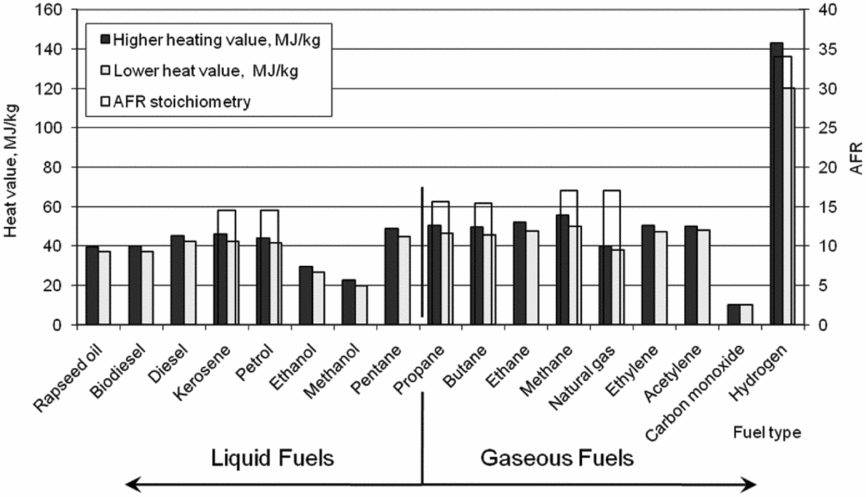
The value of energy density characterises the storage ability of the fuel. The higher the energy density, the smaller the tank volume needed to be integrated into the aircraft to guarantee an acceptable flight range.
Figure 3 shows the comparison of boiling temperatures (higher and lower) and densities for most known fuels. Since the density values of gaseous fuels at ambient pressure are very low compared to the liquid fuels (Fig. 3) demonstrates densities of gaseous fuels.
Higher boiling temperature and density of liquid and gaseous fuels.

For example, propane gaseous fuel compressed up to 5 bar, will condense at ambient temperature below 0°C. This temperature is reached when the aircraft climbs to the higher flight altitude. In case of liquid butane fuel compressed to 5 bar in the fuel system, a vaporisation at ground as a cause of higher ambient temperature and solar irradiation above 50°C is possible. Hence, for estimation of physical properties of butane-propane as aviation fuel, different atmosphere conditions have to be considered.
2.3 Flame temperature and laminar flame speed
To reach an optimal combustion performance, the temperature and flame speed(Reference Richards and Lefebvre15,Reference Warnatz, Dibble and Maas16) of considered fuels have to be estimated in the first step. The studies were based on data analysis of typical simplified burner, which were performed using software LOGE(17), as well as test bench measurements. The simulation was based on a model burner without heat losses. The flame temperature in case of kerosene was close to the values for combustion of gaseous hydrocarbons (methane, natural gas, propane-butane). Propane, butane and its mixtures show higher combustion temperatures compared to methane. According to performed simulations, the differences in the flame temperature within butane-propane mixtures are not significant. These results were validated at simplified burners experimentally.
The flame temperature curves are shown in Fig. 4 (left) along the central axis of burner geometry. The right diagram of Fig. 4 confirms that the combustion velocities of methane, propane-butane and natural gas are in the same range with kerosene(Reference Warnatz, Dibble and Maas16).
Simulated flame temperature of gaseous aviation fuels, ɸ = 1, ambient pressure and temperature (left) and Laminar flame speed of gaseous aviation fuels at ambient pressure and temperature (right).

Kerosene/butane fuel line arrangement of dual-fuel burner similar to CFDRC-Injector concept(18).

Butane-propane fuels burn with higher laminar flame speed than methane. The highest combustion speed was dedicated in case of pure butane (Fig. 4).
3.0 RESEARCH HARDWARE AND METHOD OF INVESTIGATION
3.1 Combustor test set-up
The experimental dual fuel injector is based on the CFD Research Corporation (CFDRC) concept (Fig. 5). The test injector was developed using conventional pressure atomiser for pilot line and air blast nozzle for main fuel circuit. Thus, the existing test injector design can operate using fuel-staging technology(Reference Antoshkiv, Bake and Berg3) and can be fuelled with kerosene and gaseous fuels (LNG, LH2 or butane/propane) simultaneously.
However, the performed integration of additional nozzles for LH2 or LNG is associated with various applications and safety problems that exceed the subject of this paper.
The created dual-fuel burner concept allows a parallel run with gaseous fuels and kerosene and guarantees a soft switch from kerosene to gaseous combustion mode during the engine operation. Hence, the pilot stage is equipped with a pressure atomiser providing atomisation of fuels in liquid phase (kerosene, liquid butane). The main stage can operate with liquid and gaseous fuels (methane and propane) as shown in Table 1.
Combustor stages operation mode.

Both fuel lines can operate simultaneously and separately; however, the ignition is only tested by the pilot (kerosene) line. Hence, the research will concentrate on investigation of pressure atomiser behaviour. In the experimental case the main line with an air blast nozzle is mounted into the existing burner geometry without fuel feed. The ignitor unit for the electric spark plug (Fig. 6 (1)) has discharge energy of 10 Joule. The combustor gaseous fuel feed (Reference Ballal and Lefevbre13) was controlled by a valve system (Reference Antoshkiv, Bake and Berg3).
High-speed camera (Reference Antoshkiv19) system at the atmospheric three sectors combustor test rig. 1 − ignition unit, 2 − control unit, 3 − test combustor, 4 − high-speed camera, 5 − fuel conditioning unit.

3.2 Chemiluminescence and high-speed imaging technique
The OH* chemiluminescence or the self-induced light of a flame in the range 315 nm ± 10 nm is used as a qualitative indicator of the reaction zone. This methodology is based on the following reaction:
 $$\begin{equation}
{\rm{HCO}} + {\rm{O}} \to {\rm{O}}{{\rm{H}}^*} + {\rm{CO}}
\end{equation}$$
The OH* chemiluminescence can be detected with higher sensitivity and almost without interference. On the basis of volumetric information of the OH* chemiluminescence for axisymmetric flame, a spatially resolved information of heat release can be derived after averaging of OH* images. A high-speed imaging system performed in this experiment consists of three major components: a high-speed camera (Reference Bake, Gerendas, Lazik and Doerr4), a high-speed intensified relay optics unit (IRO) and controller units (Fig. 6). A fast sensor, electronics and memory with specialised image-processing algorithms are major components of a high-speed camera that make it is more extraordinary than a conventional camera. CMOS camera (Phantom M310) synchronised with a LaVision's intensified system is implemented at the test combustor (Reference Antoshkiv19).
4.0 EXPERIMENTAL RESULTS AND DISCUSSION
After a successful ignition, kernel formation and kernel growth, the flame starts to propagate. During the first millisecond of the flame propagation phase, the ignition kernel moves in the air-flow direction and continues to grow more rapidly. Photos in Fig. 7 illustrate the axial displacement of the flame as a result of a complicated mechanism of combustor flow movement including all recirculation zones. After the spark plug discharge, the diameter of ignition kernel reaches its maximum and the kernel starts to propagate towards combustor centre (photo 1). At the same time, the combustor flow moves the extended kernel in an axial direction (photos 2 and 3). It was measured that the flame starting from the photo 1 was transported in the main flow direction toward the secondary combustion zone on the distance of 7.75 mm during 0.00044 second with the speed SF .
High-speed camera photos of the first phase of flame propagation (all measures in mm) at 4,533 fps.

The movement along 7.75 mm according to the defined scale during two frame changes (i.e. one frame interval) was done with the speed of approximately 34 m/s (4,533 fps × 0.0075 m = 34 m/s). Calculated flame-propagation speed according to simulation results amounts to 45 m/s. This difference between simulated and measured speed explained by inaccuracy of the simple method, used in subroutine, which is not able to take into account all combustion processes specifically because of one clearly defined time and space point.
The flame propagates relative to the air flow with a constant laminar burning velocity(Reference Staufer20) as shown in the Equation (6):
 $$\begin{equation}
{S_L} = \sqrt {{{4kC_f^aC_o^bA{e^{\frac{{ - E}}{{R{T_f}}}}}}
/ {\rho {g^2}cp{C_f}\frac{{Mf}}{{\rho g}}\left( {T_{f} - T_{0}} \right)}}}
\end{equation}$$
The direction of the flame front propagation is modelled as the normalised gradient of the equivalence-ratio-dependent adiabatic temperature rise.
Hence, the flame propagation speed SP can be obtained as a vector addition:
 $$\begin{equation}
{\vec{S}_P} = {\vec{S}_F} + {\vec{S}_L}
\end{equation}$$
Considering the CFD-simulation results and ignition calculations the flame propagation vectors for the given point in combustion chamber can be estimated. The vector traces refer to flame propagation trajectories, whereby the flame propagation speed is estimated as a vector sum of laminar flame speed and the flow speed. The result of the simulation makes sure that the flame can be moved by the air stream away from the combustor or can be caught by the air backstream of the recirculation zone and directed inside of combustor stabilising the combustion process.
To explain the main points of the above-described thesis, an example from the high-speed camera observation is illustrated (Fig. 8). The first photos of ignition process show the propagation and movement of ignition kernel into the airflow direction. The pressure drop (dp/p) over combustor of 3.5% was chosen as the reference value for further experiments and simulations. This value was calculated by measuring of static air pressures near the air-swirler inlet and at the combustor exit.
Flame propagation in the combustion chamber at 500 fps, dp/p = 3.5% and AFR = 30.

For the investigation of the ignition kernel and flame behaviour that was followed during the all-ignition phase, a short video at 500 fps was taken for the tested injector configuration. To show the combustion process in detail, especially to indicate the backstream clearly, the ignitor was moved downstream into the position 3/4 of flame tube height (3/4 D).
The ignition process starts with the ignition kernel formation (photo 1 in Fig. 8) and after a small time delay (photos 2 and 3), when the kernel is moved away from the combustor by the air flow after its growth, the flame illumination intensity goes down. It would be possible, that the thermal energy supplied to the ignition kernel by the spark plug and from the combustion of the ignition kernel fuel droplets and vapour is transferred to all neighbouring fuel droplets simultaneously. This thermal energy is enough to accelerate evaporation in a wide range near the ignitor and to finally ignite the mixture in this area (photo 4). The reaction speed is high enough at this time and the flame is propagating opposite to the primer zone direction (photo 4–7). This backstream flame is supported by the recirculated airflow in the recirculation zone. A big amount of fuel in this area can be considered as a main cause for the flame propagation. When the propagated flame appears in the centre of the combustion chamber (photo 8), the combustion process is supported by the radial air flow momentum. The air swirl helps to include all droplets into the combustion process along the combustor axis. At this time point, the flame will be stabilised by recirculation zone (photo 10–11) and steady combustion process will start.
Because of the much longer duration of the flame propagation phases the high-speed camera allows us to film the whole process. By acquisition of the captured photos it is possible to measure the flame propagation speed.
Figures 9 (a) and (b) give a visual comparison of the flame propagation direction during the ignition phase. This comparison shows that the simulated results are very close to the measurement, regarding the flame direction at the combustor wall as well as flame expansion in the injector area. The flame follows the main air flow downstream during the first phase of flame propagation in the combustor or flame tube wall and turns back (upstream) exactly following the simulated vector trajectories to reach the recirculation zone.
Comparison between simulated (a) and photographed (b) kerosene flame propagation traces at atmospheric conditions, dp/p = 3.5% and AFR = 30 and photographed flame propagation at laser spark plugs (c).

The experiment has been repeated several times. Similar flame propagation trend was recorded at each high-speed camera photo. For the given comparison the most clearly filmed case was chosen.
As it was mentioned in Ref. (Reference Antoshkiv, Bake, Bagchi and Berg21), the main difference between the laser ignition and electric spark plug ignition consists in the mechanism of the flame propagation phase. The CFD simulation(Reference Antoshkiv, Bake, Bagchi and Berg21) showed flame propagation vectors at the same discharge positions for both cases. The electric spark plug ignites the fuel vapour at the upper combustor wall (flame tube). This flame kernel grows and the flame moves with the air flow downstream. Because of the higher radial growth, the flame spreads into the recirculation area and turns back. The flame propagates upstream and stabilises in the central recirculation zone. In the case of laser ignition, the time gap between the laser beam and fully stabilised combustion is much shorter. Thus, the laser ignition causes short and smooth flame propagation directly into the stable zone. This fact explains the higher ignition probability that has been measured(Reference Antoshkiv, Bake, Bagchi and Berg21) for the laser system. All illustrated facts show that the investigated laser ignition has many advantages in comparison to the conventional ignition system. However, the application of this system in the gas turbine combustor has to be developed to meet reliability and cost requirements.
4.2 Experimental comparison between kerosene and gaseous fuel ignition
The behaviour of the flame after ignition of butane and kerosene was monitored using the high-speed camera. Based on these experiments the statements regarding the variations of the ignitability and flame propagation speed were verified. Selected frames of the high-speed imaging are shown in Fig. 10. Even when considering the individual images it is obvious that the kerosene flame spreads much slowly. The ignition of butane is completed after 15 ms, whereas the kerosene flame spreads in the combustion chamber after 74 ms.
Ignition OH*-photos sequences of butane (top row) and kerosene at dp/p = 1.5%, AFR = 30 and imaging frequency 11.475 kHz.

Figure 11 shows the estimated ignition sequence for butane and kerosene. Three ignition tests were recorded for each case. The images were normalised, corresponding 100% on each case to the intensity of a stable flame. At timepoint t = 0 ms, the ignition moment was selected. The ignition takes place electrically and the spark discharge was out after 2 ms. Furthermore, Fig. 11 illustrates that butane ignites earlier than kerosene. The flame propagation takes place nearly without ignition delay and the further growth of the flame can be observed after 2 ms. Thus, the full ignition procedure takes around 15 ms. Due to the high flame propagation speed of ignited vaporised butane, combustion starts nearly after spark plug discharge. This effect is well visible at the ignition (over 100% of the normal flame intensity in the picture).
Comparison of ignition procedure flame intensities of butane and kerosene.
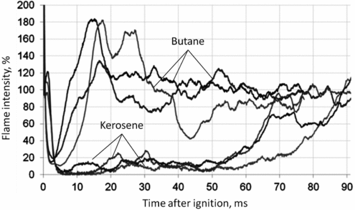
The kerosene ignition differs from the butane ignition significantly. Initially, a breakdown of the flame propagation direction takes place towards burner (Fig. 9). This behaviour of the flame has been investigated using a similar burner(Reference Antoshkiv19). The initial ignited flame fades out after 5 ms and thereby takes significantly longer than the butane flame, which fades out after 2 ms.
Afterwards, the flame propagates with low intensity in the combustion chamber until approximately 55 ms when the flame propagation speed increases. The flame propagation is completed after 70 to 90 ms. The details of this phenomenon were investigated in Ref. (Reference Antoshkiv19).
4.3 Analysis of experimental results
In this step, the achieved experimental results were analysed and compared to the experimental results from the literature. It was experimentally confirmed that at higher injected pressure SMD decreases. It has to be mentioned that liquid butane injection pressure was varied from 5 to 50 bar(Reference Antoshkiv, Bake and Berg3). To explain the differences in the behaviour of ignition kernel formation and flame propagation in case of kerosene and gas ignition, the method for calculation of minimal ignition energy has to be applied. In addition, the physical mechanism of mixture formation in case of liquid fuels includes atomisation and evaporation. As soon the radiation from the ignition sphere is neglected, the heat transfer can be considered as the summary of the following terms:
 $$\begin{equation}
\frac{\partial }{{\partial t}}\int\limits_V {\rho TdV} = - \int\limits_S^{} {\rho T\vec{v}\vec{n}} dS + \int\limits_S {k\nabla T\vec{n}dS} + \int\limits_V {\dot{q}dV}
\end{equation}$$
In this case, S and V represent the surface and volume of the ignition kernel, respectively. The vector
 $\vec{n}$
is normal to the surface and the vector
 $\vec{v}$
describes the velocity of the gas flow on the surface.
It has to be assumed that the ignition process is in equilibrium at the defined time point, hence ∂/∂t = 0. In addition, the speed of kernel growth is also negligibly small in comparison to the fluid velocity.
 $$\begin{equation}- \int\limits_S {k\nabla T \cdot \vec{n}dS} = \int\limits_V {\dot{q}dV}
\end{equation}$$
Although the temperature gradient on the kernel surface is constant, a linear decrease along the radius according to Mellor(Reference Mellor10) can be approximated:
 $$\begin{equation}
\nabla T = {{2({T_f} - {T_0})}
/ {{d_q}}}
\end{equation}$$
Since the temperature in the combustion zone is constant, the temperature gradient is assumed to be constant. If the Prandtl number and the heat capacity on the kernel surface are constant:
 $$\begin{equation}
2k\pi {d_q}({T_f} - {T_0}) = 2\frac{\eta }{{\Pr }}\pi {d_q}^3({T_f} - {T_0}) = \int\limits_V {\dot{q}dV}
\end{equation}$$
In Equation (7) it is assumed that the temperature at the spark plug electrode is high enough to initiate a fast evaporation of the fuel droplets inside of kernel volume, the fuel droplets are equally distributed and the mixing/reaction times are high enough. Furthermore, the fuel vapour is converted at an adiabatic flame temperature to the combustion products. Based on this assumption and considering the experimental values for the activation energy(Reference Spadaccini and TeVelde22,Reference Westbrook and Dryer23) , the source term (RHS of Equation (9)) can be rewritten as follows:
 $$\begin{equation}
\int\limits_V {\dot{q}dV} = \Delta {h_{{\rm{comb}}}}C_f^aC_o^bA{e^{\frac{{ - E}}{{R{T_f}}}}}\frac{\pi }{6}d_q^3 - {q_{{\rm{evap}}}},
\end{equation}$$
whereas q evap is the heat, which is needed for droplet evaporation. The chemical reactions in the ignition kernel are modelled with assumption of equilibrium. A detailed discussion of the chemical reactions is given in Ref. (Reference Staufer20).
The equation for droplet vaporisation can be determined as follows:
 $$\begin{equation}
{\dot{q}_{{\rm{evap}}}} = {\dot{m}_{{\rm{evap}}}}\Delta {h_{{\rm{evap}}}}
\end{equation}$$
The latent heat calculation method for liquid and vaporised Jet A-1 was proposed by Gracia-Salcedo, Brabbs, and McBride(Reference Gracia-Salcedo, Brabbs and McBride24). The evaporation rate can be calculated using correction term by Ranz and Marshall(Reference Ranz and Marshall25). The temperature- and pressure-dependent approximation is recommended by Rachner(Reference Rachner26). Equation (12) illustrates that the heat of combustion, used for the kernel propagation after first ignition phase, is reduced by amount of energy, required for droplets evaporation. Therefore, the speed of kernel propagation after ignition is slowed down by the energy loss for droplets evaporation. However, in the case of butane fuel ignition, a much smaller auxiliary energy for evaporation is needed, therefore energy released by combustion is used for ignition kernel propagation. Thus, this fact causes faster flame propagation in the case of butane combustion.
5.0 CONCLUSIONS
Different alternative fuels are able to be used in aero-engines in the future, however, the ignition performance depends on its physical and chemical properties. In general, the ignitability depends on many factors, i.e. combustor geometry, ignitor position, air flow condition, fuel atomisation quality, etc. The influences of these factors on the ignitability were discussed in detail in Ref. (Reference Antoshkiv19). The method to predict the optimal position of the spark plug, based on the function of minimum ignition energy for the first ignition phase, was used.
Although the ignition procedures of kerosene are well known, the ignition behaviour for fuels in gaseous phase has been observed and investigated in detail in this paper. A method for experimental definition of ignition parameters using a high-speed camera was applied. With the help of this technique, the principal comparison between the flame propagation for kerosene and gaseous fuel (propane) injected in liquid state into the annular combustor was achieved. The proposed method allowed us to observe the behaviour of OH* radicals in the combustor chamber. It was shown that kerosene ignition takes significantly longer time than propane ignition, since the propagated kerosene flame is following the ‘S-shape’ character, which leads to the delay in the ignition. The analysis of the measuring results illustrated the different trajectory during butane ignition when ignition kernel propagates directly into the central recirculation zone. The application of alternative ignition systems enables the future improvement of ignitability of an annular combustor. In addition to the already known configurations of ignition system, the use of lasers with smaller ignition energy in the gas turbine combustion chambers operating on butane-propane mixtures, offers new opportunities for ignition kernel creation in all possible points inside of combustion zone. It has to be mentioned that a minor experience of laser ignition use in gas turbines is existing at present time. Therefore, large research and development works have to be done to enable the possible application of laser ignition in future aero-engines.
As stated above, the accomplished experiments confirmed that the flame kernel propagates in case of gaseous fuels significantly faster compared to corresponding ignition phase of kerosene. This fact leads to elimination of flame back-flow zone and sequentially earlier stabilisation of gas combustion in the primary zone. Obviously, the spark plug discharge activates reactions of air-hydrocarbons mixture in gaseous state only. It has to be mentioned that a part of energy in case of liquid fuel ignition is offered for fuel evaporation (gas state preparation) simultaneously minimizing the energy amount for flame propagation. Hence, the ignition mechanism of gaseous fuels is less complicated, more efficient and the problem with wet ignitor electrodes can be eliminated.
Nevertheless, the analysis of ignition procedure in an aero-engine depending on properties of possible fuels for new designed combustors was done. Based on achieved knowledge about flame behaviour, it can be concluded that no significant modifications of aero-engine combustor hardware for ignition of gaseous fuels are required. Moreover, described ignition models in combination with CFD allow us to estimate the ignitability of different fuels using its main parameters, i.e. (density, heating value, flame temperature, laminar flame speed, possible evaporation values, mixture concentration at the ignitor) and the combustor geometry.
Finally, it can be summarised that the paper showed viable options how to investigate the flame behaviour after a spark discharge and introduced the possibility of gaseous fuels ignition. However, to apply the achievements of performed research work in aero-engines, further investigation on high-altitude relight performance at elevated pressure levels is necessary.



