NOMENCLATURE
-
 $\mathbf{B}$
-
gradient matrix
-
$\mathbf{b}$
-
distributed external load
-
$\mathbf{D}$
-
elastic moduli matrix
-
$\mathbf{f}$
-
load vector
- h
-
material thickness
-
$\mathbf{K}$
-
stiffness matrix
-
$\mathbf{N}(x, y)$
-
shape functions
-
$\mathbf{u}$
-
displacement vector
-
${\dot{\mathbf{u}},\ \ddot{\mathbf{u}}}$
-
time derivatives of displacement vector
- x, y
-
in-plane coordinates
- z
-
normal coordinate


Greek Symbols
-
$\varepsilon_{ij}$
-
deformation tensor
-
$\rho$
-
material density
-
$\sigma_{ij}$
-
stress tensor


1.0 INTRODUCTION
Thin fabric composite structures are used for different engineering applications, so different research groups have studied their properties. Commonly recognised areas of interest include predicting the elastic behaviour of woven fabric composites(Reference Tan, Tong and Steven1,Reference Naik and Shembekar2,Reference Naik and Ganesh3) , predicting the mechanical behaviour, including the strength, of woven fabric-reinforced composites(Reference Ishikawa and Chou4,Reference Barbero, Damiani and Trovillion5) and homogenisation techniques for fabric structures, mostly based on repeating unit cell geometry(Reference Dixit and Mali6). Finite element analysis and theoretical analysis are the most common research methods applied in these areas.
Any fabric composite is a complex multiscale structure in which three structural levels are commonly distinguished—the micro-level of fibres, the meso-level of yarns and the macro-level of relatively large fabric parts. Different problems are addressed using models that target different structural levels. Research that aims to study the micro-structure uses more complicated physical models(Reference Lurie, Below and Tuchkova7,Reference Belov and Lurie8) , the study of the meso-structure typically requires handling very complex geometry(Reference Hewitt, Brown and Clarke9) while modelling of macro-structures is commonly built around continuum medium models(Reference Jenkins10,Reference Sathe, Benney, Charles, Doucette, Miletti, Senga, Stein and Tezduyar11,Reference Miyazaki12) .
In the present study we concentrate on the macro-level. Our research is mostly inspired by the fact that fabric composites are becoming an essential part of impact shields that protect spacecraft from micro-meteoroids and orbital debris. Present protection systems are based on the original Whipple shield(Reference Whipple13) that consists of two rigid (typically metal) layers spaced some distance from each other. This design can deal with particles with velocities up to 10–18km/s. Additional protection can be provided by stuffed Whipple shields(Reference Christiansen, Crews, Williamsen, Robinson and Nolen14), which include high-strength materials between rigid layers. The International Space Station uses different types of Whipple shields widely(Reference Christiansen, Arnold, Davis, Hyde, Lear, Liou, Lyons, Prior, Ratliff, Ryan, Giovane, Corsaro and Studor15). Moreover, the International Space Station has started to use experimental inflatable modules, which include flexible fabric protection systems without the rigid layers present in the original Whipple shield. Computer design and optimisation of stuffed Whipple shields and flexible protection systems requires modelling of high-strength fabric composites under high-speed dynamic loading.
A number of works have been published on numerical and experimental studies of fabric materials under shock load, naming(Reference Kobylkin and Selivanov16,Reference Walker17,Reference Walker18,Reference Porval and Phoenix19) as examples. Most of these consider a single, relatively large impactor moving with a velocity of 300–700m/s, which is an order of magnitude lower compared with the sound speed in the material. However, for stuffed Whipple shields the load is completely different—the initial particle is destroyed by the outer rigid layer, then the fabric layer is exposed to a cloud of small fragments distributed over time and space and moving with a velocity of around 5–9km/s. From the mathematical modelling point of view, this load profile means that it is not possible to consider the problem to be quasi-static, since the speed of the fragments is comparable to the sound speed in the composite membrane. The stress–strain state of the composite layer should thus be calculated as a dynamic problem, and the elastic waves caused by the impact should be analysed.
Modelling stuffed Whipple shields requires consideration of a relatively large specimen of flexible composite with characteristic thickness ranging from 0.1 to 5.0mm and in-plane size of 0.1–1.0m. Based on this fact, the present study operates on the macro-level only, and describes the specimens as a continuum anisotropic medium using effective parameters.
Modelling a thin layer under asymmetric loading requires three degrees of freedom for each point of the specimen. The present study aims to achieve this for an arbitrary anisotropic material while still describing the layer as a 2D object in 3D space, since this allows a reduction in the computational time compared with full solid 3D models. This work is based on the models for thin fibres and membranes similar to Ref.(Reference Rakhmatulin and Demianov20), although we do not obtain analytical solutions for particular cases; rather, we solve the equations numerically and study the convergence rate of the numerical scheme. The same mathematical model and numerical method can be used later for the numerical study of different processes in thin composite layers, such as ultrasound propagation, non-destructive testing procedures and vibrations.
2.0 MATHEMATICAL MODEL
2.1 Notation
All the computations below are performed in Cartesian coordinates with the OX and OY axes lying in the plane of the undeformed membrane and the OZ axis orthogonal to that plane. The vector
 ${(x_0, y_0, z_0)^{\mathrm{T}}}$
denotes the initial coordinates of the point of the specimen in the undeformed state, while the vector
 ${(x, y, z)^{\mathrm{T}}}$
denotes the coordinates of the same point at a given moment of time. Let
 \begin{equation*}\mathbf{u} = \begin{pmatrix} u \\ v \\ w \end{pmatrix} = \begin{pmatrix} x - x_0 \\ y - y_0 \\ z - z_0 \end{pmatrix}\end{equation*}
be the displacement vector.
2.2 Assumptions
The membrane is considered to be an object with a characteristic size in one dimension (z) that is several orders of magnitude smaller than in the other two. Due to this fact, only the displacement of the mid-surface of the membrane in considered(Reference Liu, Tian, Yan and Hu21). Based on this, we suggest that the difference in displacement in z-direction can be neglected:
 \begin{equation} \mathbf{u}(x, y, z) = \mathbf{u}(x, y)\end{equation}
Thus, the membrane is effectively a 2D object in 3D space.
Only small strains are considered. Cauchy’s strain tensor in the following form is used:
 \begin{equation} \varepsilon_{ij} = \frac{1}{2}\left( \frac{\partial u_i}{\partial x_j} + \frac{\partial u_j}{\partial x_i} \right)\end{equation}
We suppose that the materials are subject to Hooke’s law at the deformation rates considered:
 \begin{equation} \sigma_{ij} = C_{ijkl}\varepsilon_{kl}\end{equation}
The assumptions of small strains and linear elasticity up to destruction are generally valid for rigid composites during high-speed interactions(Reference Beklemysheva, Vasyukov, Ermakov and Petrov22). Other materials may show different behaviour; in this case, they will not be covered by the model presented in this work.
2.3 Stress–strain and strain–displacement relations
We use the following vector notation for displacements in 3D linear elastic theory:
 \begin{equation} \varepsilon = \begin{pmatrix} \frac{\partial{u}}{\partial{x}} & \frac{\partial v}{\partial y} & \frac{\partial w}{\partial z} & \frac{\partial u}{\partial y} + \frac{\partial v}{\partial x} & \frac{\partial v}{\partial z} + \frac{\partial w}{\partial y} & \frac{\partial w}{\partial x} + \frac{\partial u}{\partial z} \end{pmatrix}^{\mathrm{T}} \end{equation}
However, due to the kinematic assumption in Equation (1), the differential operator
 $\frac{\partial}{\partial z}$
is always zero over the displacement fields we consider. Considering that, we use the following notation for strains:
 \begin{equation*} \varepsilon = \mathbf{Su} \end{equation*}
with the linear differential operator
 $\mathbf{S}$
defined as
 \begin{equation} \mathbf{S} =\left(\begin{array}{c@{\quad}c@{\quad}c} \frac{\partial}{\partial x} & 0 & 0 \\\\[-7pt] 0 & \frac{\partial}{\partial y} & 0 \\\\[-7pt] 0 & 0 & 0 \\\\[-7pt] \frac{\partial}{\partial y} & \frac{\partial}{\partial x} & 0 \\\\[-7pt] 0 & 0 & \frac{\partial}{\partial y} \\ \\[-7pt] 0 & 0 & \frac{\partial}{\partial x} \end{array} \right) \end{equation}
Hooke’s law then takes the form
 \begin{equation} \mathbf{\sigma} = \begin{pmatrix} \sigma_{xx} &\quad \sigma_{yy} &\quad \sigma_{zz} &\quad \tau_{xy} &\quad \tau_{yz} &\quad \tau_{xz} \end{pmatrix}^{\mathrm{T}} = \mathbf{D\varepsilon} \end{equation}
with D being the compliance matrix. In the most general case,
 $\mathbf{D}$
is symmetric and depends on 21 independent elastic moduli.
2.4 Equations of motion
We derive the equations of motion using the virtual work principle. Let us first consider the equilibrium conditions for the unit volume under external loading in the static case. Let
 $\delta u, \delta \varepsilon$
be variations of the corresponding values.
 $\mathbf{\overline{b}}$
denotes the distributed external force per unit volume. Then, the virtual work per unit volume is given by
 \begin{equation} \delta w = \delta\mathbf{\varepsilon^{\mathrm{T}} \sigma} - \delta\mathbf{u^{\mathrm{T}}} \bar{\mathbf{b}} \end{equation}
With u sufficiently smooth,
 $\delta\varepsilon = S\delta\mathbf{u}$
. For the transition to the dynamic case, according to d’Alembert’s principle, we add a distributed inertia force:
 \begin{equation*}\bar{\mathbf{b}} = \mathbf{b} -\rho\ddot{\mathbf{u}},\end{equation*}
where
 $\mathbf{b}$
is the distributed load and
 $-\rho\ddot{\mathbf{u}}$
is the inertia force. Taking this into account along with Equations (5), (6), we get the equation
 \begin{equation*}\delta\mathbf{u^{\mathrm{T}}}\left(\mathbf{S^{\mathrm{T}}DSu} + \rho\ddot{\mathbf{u}} - b\right) = 0,\end{equation*}
which must be satisfied for any variation
 $\delta\mathbf{u}$
. The term in brackets must thus be equal to zero. We finally get the equation of motion as
 \begin{equation} \mathbf{S^{\mathrm{T}}DSu} + \rho\ddot{\mathbf{u}} - {\mathbf{b}} = 0\end{equation}
Further expansion of this equation appears inconvenient, in particular when
 $\mathbf{D}$
is given by more than two independent parameters, as for an isotropic material. On the other hand, precisely those cases are of interest when modelling composite materials. Thus, in the following section, we derive the governing equations for the computational element.
3.0 NUMERICAL METHOD
The Finite Element Method (FEM) is chosen for the task. One of the advantages of this approach is the possibility of treating complex geometries, laying the foundation for future study of the movement of perforated constructions or screens with holes created by impacts.
The formulation of the computational algorithm follows the general methodology described in Ref.(Reference Zienkiewicz and Taylor23). This paper differs from the traditional approach in that the material points are parameterised with two coordinates
 $(x_0, y_0)$
but have three degrees of freedom (u, v, w). Traditionally, for 2D problems, only formulations with either one (normal, w) or two (in-plane, (u, v)) degrees of freedom are studied. This is because, for an isotropic material, due to the particular structure of the matrix
 $\mathbf{D}$
, the system of equations of motion splits into two systems, namely a wave equation for w and Lamé equations for the in-plane motion, which can be solved independently.
For a general anisotropic material, the structure of the elastic moduli tensor
 $\mathbf{D}$
may be different, depending on the degrees of material symmetry possessed by the specimen. For example, a monoclinic medium, i.e. one that has only one plane of material symmetry, does not allow the system of equations to be split in this way. The equations for a monoclinic medium are discussed in more detail in the Appendix, since they are rather complicated and their exact representation does not influence the model or method presented in the following sections. However, their representation in the Appendix explains why the authors cannot just split the system of equations of motion into two systems for some materials.
3.1 Domain decomposition
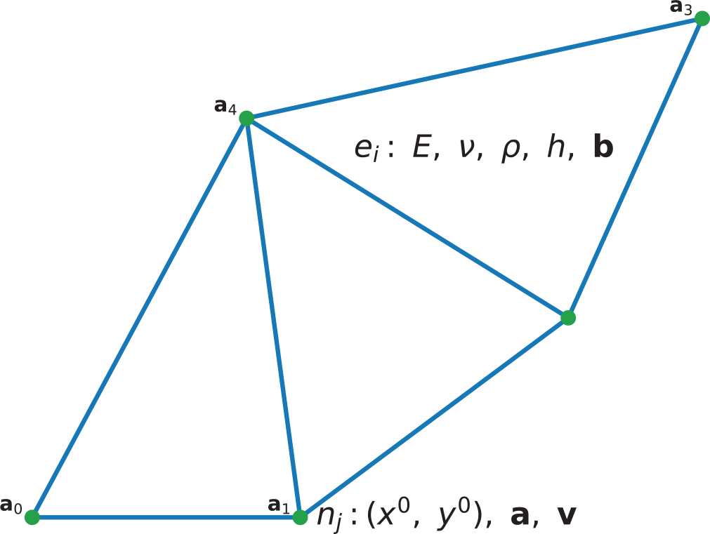
The computational domain corresponds with the physical membrane. An unstructured grid of triangular elements is used. We suppose the thickness h, density
 $\rho$
and elastic moduli
 $E, \nu$
of the material to be constant around the element. It is suggested that the external force
 $\mathbf{b}$
is distributed uniformly in the element. The following values are associated with the vertices: their initial coordinates
 $(x_0, y_0)$
, the displacements
 $\mathbf{a}$
and the velocities
 $\mathbf{v}$
. Figure 1 depicts an example of the domain decomposition.
3.2 Displacement approximation
Consider a triangular element with vertices
 $(x_0^m, y_0^m), (x_0^n, y_0^n), (x_0^p, y_0^p)$
. Let us denote the displacement vector at vertex i as
 \begin{equation*} \mathbf{a}_i = \mathbf{u}(x_0^i, y_0^i) \end{equation*}
Displacements are approximated in the domain of the element as linear functions of the nodal displacements by defining the shape functions
 $\mathbf{N_i}(x, y, z)$
:
 \begin{equation} \mathbf{u}(x,y,z) = \sum_{i \in \{m,n,p\}}{\mathbf{N_ia_i}} = \mathbf{Na} \end{equation}
with
 $\mathbf{N} = \left[ \begin{matrix} \mathbf{N}_m & \mathbf{N}_n & \mathbf{N}_p \end{matrix} \right]$
,
 $\mathbf{a} = \left[ \begin{matrix} \mathbf{a}_m \\ \mathbf{a}_n \\ \mathbf{a}_p \end{matrix} \right]$
— displacements of the vertices, as only a linear approximation is considered. Taking (1) into account, one gets
 \begin{equation} \mathbf{N}_i = (\alpha_i + \beta_i x + \gamma_i y)\mathbf{E} \end{equation}
with coefficients defined by
 \begin{equation} \mathbf{N}_i(x_j, y_j) = \begin{cases} \mathbf{E},\ i = j \\[4pt] \mathbf{0},\ i \neq j \end{cases}\ i,\ j \in \{m,n,p\} \end{equation}
The final coefficients for given shape functions are given by
 \begin{eqnarray} \alpha_i = \frac1{S_e}\begin{vmatrix} x_j & y_j \\ x_k & y_k \end{vmatrix} \quad \beta_i = -\frac1{S_e} (y_k - y_j) \quad \gamma_i = \frac1{S_e} (x_k - x_j) \quad S_e = \begin{vmatrix} 1 &\quad x_i &\quad y_i \\ 1 &\quad x_j &\quad y_j \\ 1 &\quad x_k &\quad y_k \end{vmatrix}\notag \end{eqnarray}
3.3 Approximate stress and strain
Let us approximate Equation (4) by substituting the displacement with the approximation from Equation (9)
 \begin{equation} \mathbf{\varepsilon} = \mathbf{Su} = \mathbf{SNa} = \mathbf{Ba} \end{equation}
Taking into account the formulas for
 $\mathbf{N}$
, the matrix
 $\mathbf{B}$
becomes
 \begin{equation} \mathbf{B} = \left(\begin{array}{@{}c@{\quad}c@{\quad}c@{}} \mathbf{B}_1^1 & \mathbf{B}_2^1 & \mathbf{B}_3^1 \\ \\[-7pt] \mathbf{B}_1^2 & \mathbf{B}_2^2 & \mathbf{B}_3^2 \end{array}\right) \end{equation}
 \begin{equation} \mathbf{B}_i^1 = \begin{pmatrix} \beta_i &\quad 0 &\quad 0 \\ 0 &\quad \gamma_i &\quad 0 \\ 0 &\quad 0 &\quad 0 \end{pmatrix}, \quad \mathbf{B}_i^2 = \begin{pmatrix} \gamma_i &\quad \beta_i &\quad 0 \\ 0 &\quad 0 &\quad \gamma_i\\ 0 &\quad 0 &\quad \beta_i \end{pmatrix} \end{equation}
Stress and strain are connected via Hooke’s law as expressed in equation (6). Substituting with the equation for deformation from above, one gets
 \begin{equation} \sigma = \mathbf{D\varepsilon} = \mathbf{DBa} \end{equation}
In the current implementation, it is possible to define either all 21 independent elastic constants, or, for the case of isotropic material, the Young’s modulus E and Poisson’s ratio
 $\nu$
. The compliance matrix in the former case has the form
 \begin{eqnarray} \mathbf{D} = \begin{pmatrix} \mathbf{D}_1 &\quad \mathbf{0} \\ \mathbf{0} &\quad \mathbf{D}_2 \end{pmatrix}. \mathbf{D}_1 = \frac{E}{(1 + \nu)(1 - 2\nu)} \begin{pmatrix} 1 - \nu & \nu & \nu \\ \nu & 1 - \nu & \nu \\ \nu & \nu & 1 - \nu \end{pmatrix} \end{eqnarray}
 \begin{eqnarray} \notag \mathbf{D}_2 = \frac{E}{(1 + \nu)(1 - 2\nu)} \begin{pmatrix} \frac{1-2\nu}2 &\quad 0 &\quad 0 \\[4pt] 0 &\quad \frac{1-2\nu}2&\quad 0 \\[4pt] 0 &\quad 0 &\quad \frac{1-2\nu}2 \end{pmatrix} \end{eqnarray}
3.4 Virtual work for the element
Let us obtain the approximation for Equation (7) by substituting the variations with finite element approximations in Equations (9), (12):
 \begin{equation} \delta\mathbf{u} = \mathbf{N}\delta\mathbf{a}, \quad \delta \mathbf{\varepsilon} = \mathbf{B}\delta\mathbf{a} \end{equation}
Taking these into account along with (15), the virtual work Equation (7) becomes
 \begin{equation} \delta w = \delta\mathbf{\varepsilon^{\mathrm{T}} \sigma} - \delta\mathbf{u^{\mathrm{T}}} \bar{\mathbf{b}} = \mathbf{\delta a^{\mathrm{T}}}\left(\mathbf{B^{\mathrm{T}} D Ba - N^{\mathrm{T}}} \bar{\mathbf{b}}\right) \end{equation}
Let us integrate the equation over the element volume and introduce fictitious nodal forces
 $\mathbf{q_i}$
that balance the internal elastic forces and external loads:
 \begin{equation} \delta \mathbf{a}^{\mathrm{T}} \left(\int_{V_e}\mathbf{B^{\mathrm{T}} D Ba}\mathrm{d}V - \int_{V_e} \mathbf{N^{\mathrm{T}}}\bar{\mathbf{b}}\mathrm{d}V \right) = \delta\mathbf{a}^{\mathrm{T}}\mathbf{q}_e \end{equation}
Te transition to the dynamic case is done according to d’Alembert’s principle:
 \begin{equation} \bar{\mathbf{b}} = \mathbf{b} - \rho \ddot{\mathbf{u}}, \end{equation}
where
 $\mathbf{b}$
is the external force and
 $-\rho\ddot{\mathbf{u}}$
is the force of inertia. For acceleration, we use the same approximation as for displacement:
 \begin{equation} \ddot{\mathbf{u}}(x, y) = \mathbf{N}(x, y)\ddot{\mathbf{a}}. \end{equation}
Taking into account Equation (20) and (21) for the computational element from Equation (19), one finally gets
 \begin{equation} \mathbf{M}_e\ddot{\mathbf{a}} + \mathbf{K}_e\mathbf{a} + \mathbf{f}_e = \mathbf{q}_e \end{equation}
Here, the following matrices are introduced
 \begin{eqnarray} \quad\ \mathbf{K}_e = \int_{V_e}{\mathbf{B^{\mathrm{T}}DB}}\mathrm{d}V \text{---stiffness matrix}\end{eqnarray}
 \begin{eqnarray} \mathbf{M}_e = \rho\int_{V_e}{\mathbf{N^{\mathrm{T}}N}}\mathrm{d}V \text{---mass matrix}\end{eqnarray}
 \begin{eqnarray} \ \ \mathbf{f}_e = - \int_{V_e} \mathbf{N^{\mathrm{T}}b}\mathrm{d}V_e \text{---load vector} \end{eqnarray}
3.5 Global equations assembly
We now have to account for the effect of all the elements to which a certain vertex belongs. Instead of a local displacement vector, defined in Equation (9), consider a
 $3N_{\rm nodes}$
-dimensional vector consisting of the stacked displacement vectors of each vertex.
Thus, we introduce the global matrices
 $\mathbf{K}$
and
 $\mathbf{M}$
with dimensions
 $3N_{\rm nodes}\times3N_{\rm nodes}$
and the vector
 $\mathbf{f}$
with dimension
 $3N_{\rm nodes}$
. They are assembled using the following rules:
 \begin{eqnarray} \mathbf{K}_{ij} = \sum_{e}\mathbf{K}^e_{ij} \end{eqnarray}
 \begin{eqnarray} \mathbf{M}_{ij} = \sum_{e}\mathbf{M}^e_{ij} \end{eqnarray}
 \begin{eqnarray} \mathbf{f}_i = \sum_{e}\mathbf{f}^e_{i} \end{eqnarray}
Here
 $\mathbf{K}_{ij}$
denotes a
 $3\times 3$
block of
 $\mathbf{K}$
, standing at the intersections of the row and column corresponding to the i-th and j-th vertex.
 $\mathbf{K}_{ij}^e$
is a local stiffness matrix defined above in Sect. 3.4. The summation is over for all the elements containing both the i-th and j-th vertex. The fictitious nodal forces are summed too, and, obviously, the sum equals zero in case of equilibrium. Eventually, one arrives at the following equation for the whole domain, analogous to Equation (22):
 \begin{equation} \boxed{\mathbf{M}\ddot{\mathbf{a}} + \mathbf{K}\mathbf{a} + \mathbf{f} = 0} \end{equation}
3.6 Applying constraints
To study pinpoint strikes, we need to constrain the velocity of the strike point. Problems involving a membrane with fixed border may also arise. We shall demonstrate that such constraints can be taken into account without changing the structure of the governing Equation (29). Let us fix node i. In
 $\mathbf{K}$
, we fill the line
 $\mathbf{K}_{ik}, k\in \overline{1, N_{\rm nodes}}$
with zeros. In
 $\mathbf{M}$
, let
 $M_{ii} = \mathbf{E}$
, and fill the rest of the blocks
 $M_{ik}, k \neq i$
with zeros. Finally, in the vector
 $\mathbf{f}$
, we fill
 $\mathbf{f}_i$
with zeros. As a result, the system now contains an equation
 $\ddot{\mathbf{a}}_i = \mathbf{0}$
, i.e.
 $\mathbf{v}_i(t) = \mathbf{v}_{\rm fix}$
. To constrain the displacement, we determine
 $\mathbf{v}_{\rm fix} = \mathbf{0}$
.
3.7 Time integration
The procedure described above allows us to reduce the initial problem for the PDE to an ODE problem as expressed in Equation (29). We then integrate this equation numerically using the Newmark method(Reference Newmark25):
 \begin{align} \dot{\overline{\mathbf{a}}}_n &= \dot{\mathbf{a}}_n + \tau(1-\beta_1)\ddot{\mathbf{a}}_n \notag\\[3pt] \overline{\mathbf{a}}_n &= \mathbf{a}_n + \tau\dot{\mathbf{a}}_n + \frac12\tau^2(1 - \beta_2)\ddot{\mathbf{a}}_n \notag\\[3pt] \ddot{\mathbf{a}}_{n+1} &= - A^{-1}\left(\mathbf{f}_{n+1} +\mathbf{K}\overline{\mathbf{a}}_n \right),\quad A = \mathbf{M} + \frac{1}{2}\tau^2\beta_2\mathbf{K} \\[3pt] \dot{\mathbf{a}}_{n+1} &= \dot{\overline{\mathbf{a}}}_n + \beta_1\tau\ddot{\mathbf{a}}_{n+1} \notag\\[3pt] \mathbf{a}_{n+1} &= \overline{\mathbf{a}} + \frac{1}{2}\tau^2\beta_2\ddot{\mathbf{a}}_{n+1} \notag \end{align}
If
 $\beta_2 \geq \beta_1 \geq \frac12$
, the method is unconditionally stable. If
 $\beta_1 = \frac12$
, then the method has the second order of approximation(Reference Zienkiewicz and Taylor23). For all the numerical experiments below, the parameter values
 $\beta_1 = \beta_2 = \frac12$
were used.
3.8 Remarks on computational time
When using the model and the method proposed above, we do not need to create a computational grid through the thickness direction z of the specimen. We address 3D problems, but we represent the specimen using a triangular surface mesh only. This allows us to have fewer vertices and elements in the grid compared with a full 3D model of the membrane, since we do not have vertices in the volume of the specimen. Additionally, the elements of the grid are simpler—triangles in our case, instead of tetrahedrons when using the full 3D geometry, and each vertex in the triangular grid has fewer connections compared with a tetrahedral grid. These facts cause the global matrices
 $\mathbf{K}$
and
 $\mathbf{M}$
to have fewer dimensions and be more sparse, compared with full 3D geometry modelling. Numerical solutions for smaller and sparser matrices require less computational time.
3.9 Numerical results
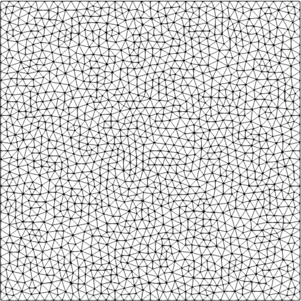
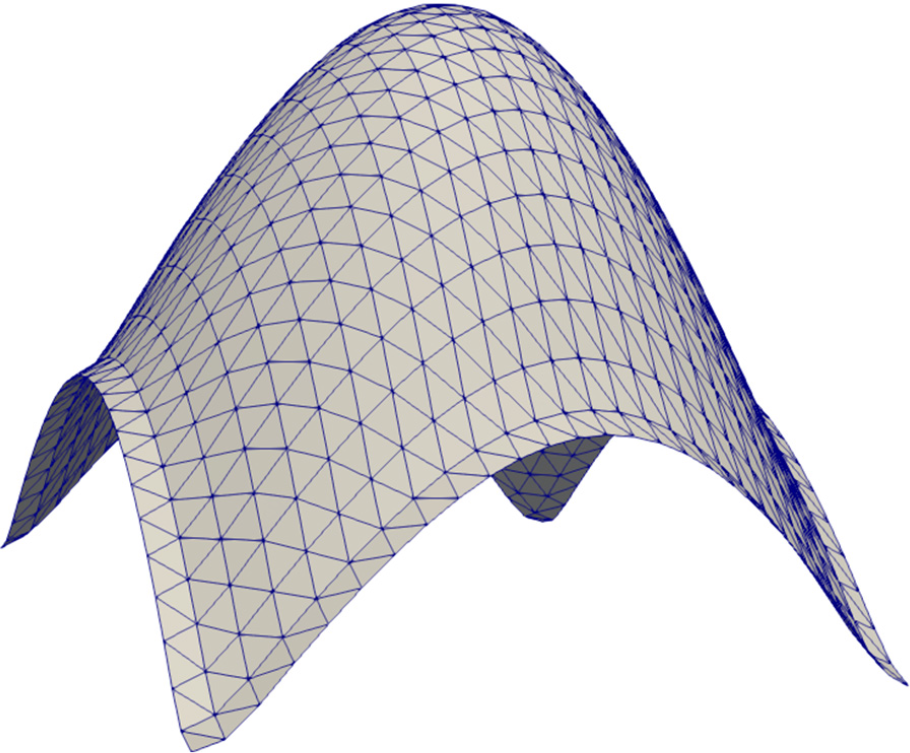
The described method works on arbitrary irregular grids. Figure 2 shows an example of a grid constructed using the gmsh mesh generator(Reference Geuzaine and Remacle26).
Sample domain decomposition. Elements
 $e_i$
and vertices
 $n_j$
are presented along with corresponding values.

Example calculation grid.

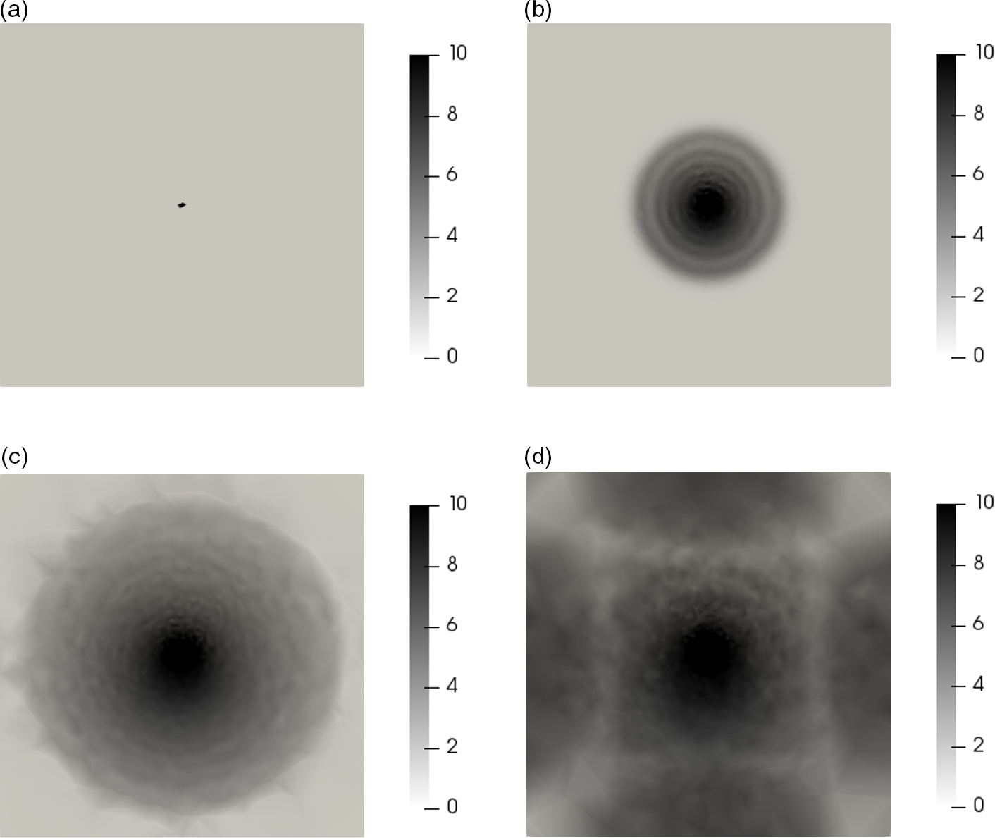
Exposure to a point load impulse, showing the dynamics of the involvement of the membrane material in the motion. The colour shows the modulus of the velocity at different points in time: (a) initial state, (b) wave propagation in the membrane, (c) wave reaches the border of the membrane, and (d) wave is reflected from the border.

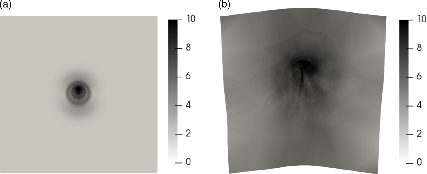
Exposure to a point load impulse at an angle of 30 degrees to the normal. The colour shows the modulus of the velocity at different points in time: (a) initial stage of loading and (b) asymmetric deformation.

Figure 3 shows an example of a calculation using this grid. A single central mesh element is impacted at a constant speed directed normal to the membrane plane. The involvement of the membrane material in the movement is shown. It can be seen that, for a symmetric formulation, the solution is symmetric and does not contain numerical artefacts.
The implemented method allows one to model asymmetric load profiles. Figure 4 shows an example of a calculation in which a blow with a constant speed is applied at an angle to the normal. The involvement of the membrane material in the motion and its substantially asymmetric deformation are seen.
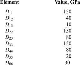
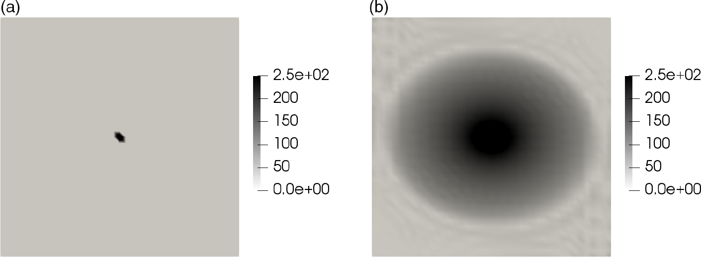
Figure 5 shows an example of a calculation using an anisotropic material model. A single central mesh element is impacted at a constant speed directed normal to the membrane plane. The elastic properties of the material are presented in Table 1. The elliptic wave pattern formed due to the anisotropy of the material is seen in the figure.
Anisotropic material elasticity matrix: non-zero elements

Anisotropic material exposed to a point load impulse. The colour shows the modulus of the velocity at different points in time. An elliptic wave pattern is formed due to the material anisotropy. (a) Initial stage of loading. (b) Wave reaches the border of the membrane.

The method not only allows one to obtain the initial membrane dynamics and elastic waves from the shock load, but also can be used to calculate deformations that develop over a considerable time. For example, Fig. 6 shows the result of calculating the deformation of the membrane under the action of a distributed load directed normal to the undeformed membrane and with a modulus
 \begin{equation} b(r) = \begin{cases} b_0\cos^2{r}, & r \leq L \\ \\[-7pt] 0, & \text{ otherwise} \end{cases} \\ \quad r = \frac{\pi}{2L}\sqrt{\left(x - \frac{1}{2}L \right)^2 + \left(y - \frac{1}{2}L \right)^2},\ L\text{---membrane size}\end{equation}
4.0 ACTUAL CONVERGENCE RATE
The scheme’s actual convergence rate was examined by using a method similar to that presented in Ref.(Reference Khokhlov and Golubev27). First, a rather coarse regular grid, composed of rectangles, each split into two triangles by a diagonal, is generated. The choice of a regular grid is dictated by the need to easily control the coarseness of the grid. The solution is calculated up to some fixed time T. The velocities and displacements at all the points of this coarse grid are saved as the baseline solution. Then, the calculations are repeated on a grid refined by splitting each rectangle into four smaller ones. The timestep is also scaled down accordingly. The norms of the difference of the displacements and velocities between consecutive solutions on finer grids are calculated. The displacements and velocities for the norm calculation are taken at the same space and time points as during the baseline solution.
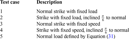
Several test cases are examined; their descriptions are summarised in Table 2. In cases 1 and 2, the loading force is applied to one central square (a pair of triangular elements) in the middle of the membrane. In cases 3 and 4, the velocity at the point closest to the geometric centre of the membrane is constrained, with the velocity vector being respectively normal or inclined at an angle
 $\frac{\pi}6$
to normal.
Test case formulations

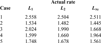
Convergence rates

Distributed load example.

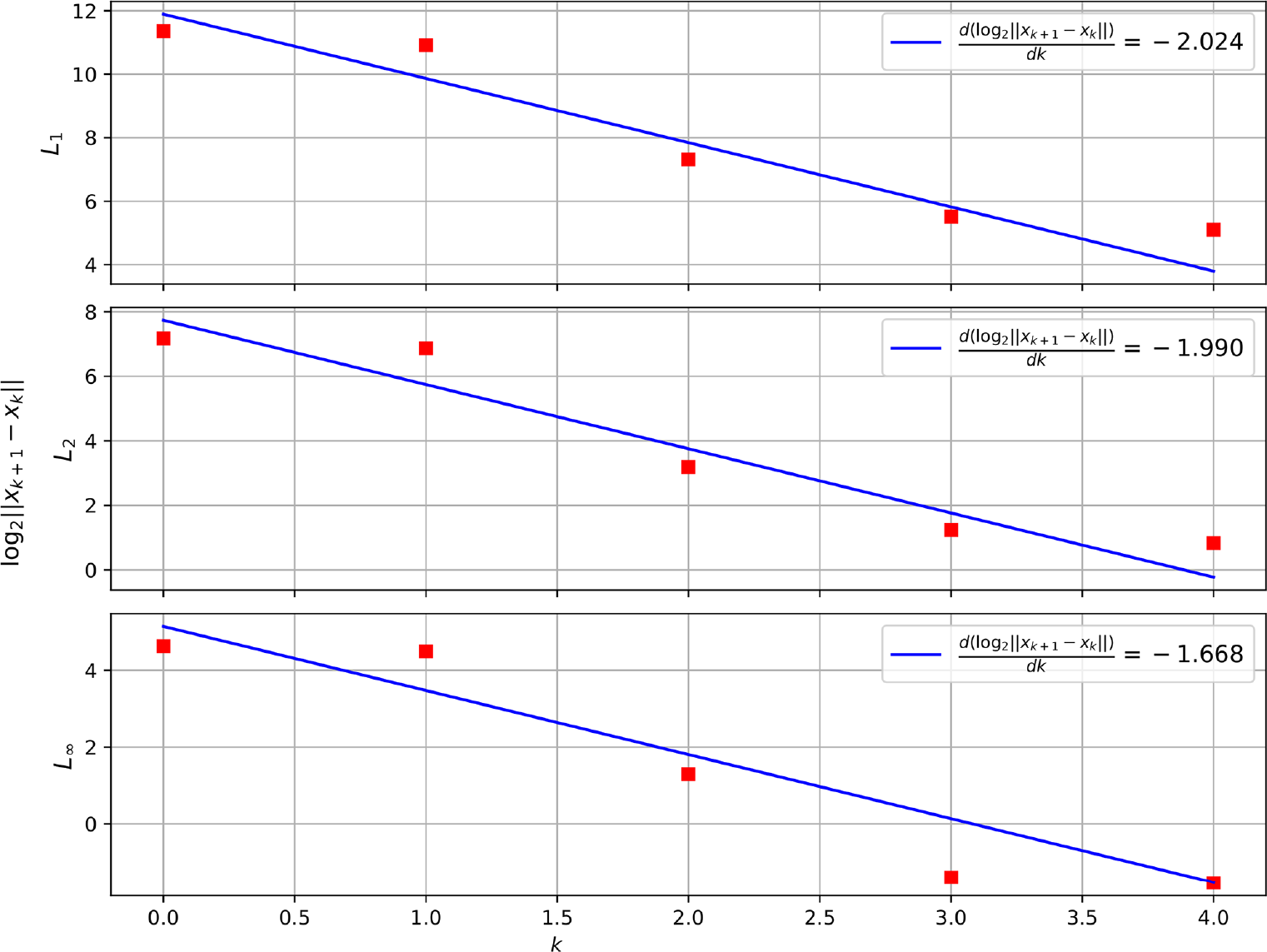
Convergence: normal strike.

To demonstrate the results of this convergence rate study, in the Figure 7 we present the plot used in the convergence rate assessment for test case 3. The number of grid refinements k is plotted on the OX axis, while the norm of the difference between the solutions on consecutive grids is plotted on a logarithmic scale on the OY axis. Three norms, namely
 $L_{1}$
,
 $L_{2}$
, and
 $L_{\inf}$
, are considered. The slope of the fitted line represents the actual convergence rate.
The results of the convergence rate study are presented in Table 3.
5.0 CONCLUSION
This paper describes a mathematical model and numerical method for modelling a thin anisotropic composite membrane under a dynamic shock load with an arbitrary time and space profile. The results presented show that the convergence rate of the numerical scheme in the worst case is 1.4 (oblique strike when using the norm
 $L_{\inf}$
), and in the best case it is 2.5 (symmetric load using any norm). This order allows the described numerical method to be applied for calculations in conjunction with field experiments. Anisotropic materials supported by the numerical method can be used to describe multilayer fabric membranes using effective parameters.
The model and the method are designed to consider the composite membrane as a 2D object in 3D space, still having an arbitrary material rheology and load profile. This approach allows a reduction in computational time compared with direct modelling using full 3D models.
An obvious limitation of the described model and method is the lack of the possibility of a detailed calculation of problems associated with destruction of the membrane. Using the presented approach, it is only possible to determine the start of failure using strain or stress thresholds. Enhancing the method to cover destruction is a topic for future work.
ACKNOWLEDGEMENTS
The work was supported by RFBR project 18-29-17027. The authors would like to thank the anonymous reviewers, who pointed out the drawbacks in the original text of the article. Their remarks helped to make the article much better. The authors are grateful to Beklemysheva K.A., PhD for long, thoughtful discussions of the results and Bot.Cafe for a warm atmosphere and great coffee.
APPENDIX
6.0 On the system of equations for monoclinic material
To expand the spatial derivatives term
 $\mathbf{S^{\mathrm{T}} D S}$
we first introduce the following block notation for convenience:
 \begin{equation} \mathbf{D} = \begin{bmatrix} \mathbf{D_1} &\quad \mathbf{T} \\[4pt] \mathbf{T^{\mathrm{T}}} &\quad \mathbf{D_2} \end{bmatrix}, \quad \mathbf{S} =\begin{bmatrix} \mathbf{S_1} \\[4pt] \mathbf{S_2} \end{bmatrix}, \quad \mathbf{S_1} =\begin{bmatrix} \frac{\partial}{\partial x}\quad & 0 &\quad 0 \\[4pt] 0 &\quad \frac{\partial}{\partial y} & \quad 0 \\[4pt] 0 &\quad 0 &\quad 0\\[4pt] \end{bmatrix} , \quad \mathbf{S_2} =\begin{bmatrix} \frac{\partial}{\partial y} &\quad \frac{\partial}{\partial x} &\quad 0 \\[4pt] 0 & \quad0 & \quad\frac{\partial}{\partial y} \\[4pt] 0 &\quad 0 &\quad \frac{\partial}{\partial x} \end{bmatrix}\end{equation}
Note that all the blocks, just as the resulting term, are 3
 $\times$
3 matrices. The following blocks are also symmetrical
 \begin{equation} \mathbf{D_1 = D_1^{\mathrm{T}},\ D_2=D_2^{\mathrm{T}},\ S_1=S_1^{\mathrm{T}}}\end{equation}
Block-matrix multiplication yields
 \begin{equation} \mathbf{ S^{\mathrm{T}}DS = S_1 D_1 S_1 + S_1 T S_2 + S_2^{\mathrm{T}} T^{\mathrm{T}} S_1 + S_2^{\mathrm{T}} D_2 S_2 }\end{equation}
Note that
 $\mathbf{S_2^{\mathrm{T}} T^{\mathrm{T}} S_1 = \left(S_1 T S_2\right)^{\mathrm{T}}}$
. The terms are
 \begin{align} \mathbf{S_1 D_1 S_1} &= \left[\begin{matrix}D_{11} \dfrac{\partial^2}{\partial x^2} & \quad D_{12} \dfrac{\partial^2}{\partial x \partial y} & \quad 0\\[11pt]
D_{12} \dfrac{\partial^2}{\partial x \partial y} & \quad D_{22} \dfrac{\partial^2}{\partial y^2} & \quad 0\\[11pt]
0 & \quad 0 & \quad 0\end{matrix}\right] \end{align}
 \begin{align} \mathbf{S_1 T S_2 + (S_1 T S_2)^{\mathrm{T}}} &= \left[\begin{matrix}2 D_{14} \dfrac{\partial^2}{\partial x \partial y} & \quad D_{14} \dfrac{\partial^2}{\partial x^2} + D_{24} \dfrac{\partial^2}{\partial y^2} & \quad D_{15} \dfrac{\partial^2}{\partial x^2} + D_{16} \dfrac{\partial^2}{\partial x \partial y}\\[12pt]
D_{14} \dfrac{\partial^2}{\partial x^2} + D_{24} \dfrac{\partial^2}{\partial y^2} & \quad 2 D_{24} \dfrac{\partial^2}{\partial x \partial y} & \quad D_{25} \dfrac{\partial^2}{\partial x \partial y} + D_{26} \dfrac{\partial^2}{\partial y^2}\\[12pt] D_{15} \dfrac{\partial^2}{\partial x^2} + D_{16} \dfrac{\partial^2}{\partial x \partial y} & \quad D_{25} \dfrac{\partial^2}{\partial x \partial y} + D_{26} \dfrac{\partial^2}{\partial y^2} & \quad 0\end{matrix}\right] \end{align}
 \begin{align} \mathbf{S_2^{\mathrm{T}} D_2 S_2} &= \left[\begin{array}{c@{\quad}c@{\quad}c} D_{44} \dfrac{\partial^2}{\partial y^2} & D_{44} \dfrac{\partial^2}{\partial x \partial y} & p_{y} D_{45} \dfrac{\partial^2}{\partial x \partial y} + D_{46} \dfrac{\partial^2}{\partial y^2} \\[13pt] D_{44} \dfrac{\partial^2}{\partial x \partial y} & D_{44} \dfrac{\partial^2}{\partial x^2} & D_{45} \dfrac{\partial^2}{\partial x^2} + D_{46} \dfrac{\partial^2}{\partial x \partial y} \\[13pt] D_{45} \dfrac{\partial^2}{\partial x \partial y} + D_{46} \dfrac{\partial^2}{\partial y^2} & D_{45} \dfrac{\partial^2}{\partial x^2} + D_{46} \dfrac{\partial^2}{\partial x \partial y} & D_{55} \dfrac{\partial^2}{\partial x^2} + 2D_{56} \dfrac{\partial^2}{\partial x \partial y} + D_{66} \dfrac{\partial^2}{\partial y^2} \end{array}\right]\end{align}
By combining the terms, one gets the spatial derivatives operator in question. For the sake of brevity of the formulas, we consider a monoclinic material, i.e. a material with only one plane of symmetry, in our case, the xy-plane. The elastic tensor for such a material takes the form
 \begin{equation}\left[\begin{array}{c@{\quad}c@{\quad}c@{\quad}c@{\quad}c@{\quad}c@{\quad}c}D_{11} & D_{12} & D_{13} & 0 & 0 & D_{16}\\ \\[-7pt]D_{12} & D_{22} & D_{23} & 0 & 0 & D_{26}\\ \\[-7pt]D_{13} & D_{23} & D_{33} & 0 & 0 & D_{36}\\ \\[-7pt]0 & 0 & 0 & D_{44} & D_{45} & 0\\ \\[-7pt]0 & 0 & 0 & D_{45} & D_{55} & 0\\ \\[-7pt]D_{16} & D_{26} & D_{36} & 0 & 0 & D_{66}\end{array}\!\!\!\!\!\right]\end{equation}
The spatial derivatives term then becomes
 \begin{equation}\mathbf{S^{\mathrm{T}}DS} = \left[\begin{array}{l@{\qquad}l@{\qquad}l}D_{11} \dfrac{\partial^2}{\partial x^2} + D_{44} \dfrac{\partial^2}{\partial y^2} & \dfrac{\partial^2}{\partial x \partial y} \left(D_{12} + D_{44}\right) & \dfrac{\partial^2}{\partial x \partial y} \left(D_{16} + D_{45}\right)\\[15pt]
\dfrac{\partial^2}{\partial x \partial y} \left(D_{12} + D_{44}\right) & D_{22} \dfrac{\partial^2}{\partial y^2} + D_{44} \dfrac{\partial^2}{\partial x^2} & D_{26} \dfrac{\partial^2}{\partial y^2} + D_{45} \dfrac{\partial^2}{\partial x^2}\\[15pt]
\dfrac{\partial^2}{\partial x \partial y} \left(D_{16} + D_{45}\right) & D_{26} \dfrac{\partial^2}{\partial y^2} + D_{45} \dfrac{\partial^2}{\partial x^2} & D_{55} \dfrac{\partial^2}{\partial x^2} + D_{66} \dfrac{\partial^2}{\partial y^2}\end{array}\right]\end{equation}
Separation of the bending problem occurs only if additional conditions
 $(D_{16} + D_{45} = 0, D_{26} = 0, D_{45} = 0)$
are satisfied; thus, this may not occur for a general monoclinic material. For this reason, all three degrees of freedom for each material point are considered simultaneously, and not the in-plane and transverse motions separately.
In contrast, for an isotropic material:
 \begin{equation} D = \left[\begin{matrix}\frac{E \left(1 - \nu\right)}{\left(1 - 2 \nu\right) \left(\nu + 1\right)} & \quad \frac{E \nu}{\left(1 - 2 \nu\right) \left(\nu + 1\right)} & \quad \frac{E \nu}{\left(1 - 2 \nu\right) \left(\nu + 1\right)} & \quad 0 & \quad 0 & \quad 0\\[10pt]
\frac{E \nu}{\left(1 - 2 \nu\right) \left(\nu + 1\right)} & \quad \frac{E \left(1 - \nu\right)}{\left(1 - 2 \nu\right) \left(\nu + 1\right)} & \quad \frac{E \nu}{\left(1 - 2 \nu\right) \left(\nu + 1\right)} & \quad 0 & \quad 0 & \quad 0\\[14pt]
\frac{E \nu}{\left(1 - 2 \nu\right) \left(\nu + 1\right)} & \quad \frac{E \nu}{\left(1 - 2 \nu\right) \left(\nu + 1\right)} & \quad \frac{E \left(1 - \nu\right)}{\left(1 - 2 \nu\right) \left(\nu + 1\right)} & \quad 0 & \quad 0 & \quad 0\\[14pt]
0 & \quad 0 & \quad 0 & \quad \frac{E}{2\left(\nu + 1\right)} & \quad 0 & \quad 0\\[14pt]
0 & \quad 0 & \quad 0 & \quad 0 & \quad \frac{E}{2\left(\nu + 1\right)} & \quad 0\\[14pt]
0 & \quad 0 & \quad 0 & \quad 0 & \quad 0 & \quad \frac{E}{2\left(\nu + 1\right)} \end{matrix} \right]\end{equation}
The conditions mentioned above are thus satisfied for the isotropic material, and the system of equations of motion can be split into two systems, which will be solved independently.