NOMENCLATURE
- AC
alternating current
- ACE
actuation control electronics
- AHP
analytical hierarchy process
- AMBSE
Agile Model-Based System Engineering
- ARP
Aerospace Recommended Practice
- BG
bond graph
- CAP
control anticipation parameter
- DC
direct current
- EASA
European aviation safety agency
- EBHA
electro-backup-hydraulic-actuator
- EHA
Electro-Hydrostatic Actuator
- FAA
Federal Aviation Administration
- FAR
Federal Aviation Regulation
- FCC
Flight Control Computer
- FCS
flight control system
- FDAL
Functional Development Assurance level
- FHA
Functional Hazard Assessment FoM figure of merit
- FTA
Fault Tree Analysis
- FTD
Failure to Dispatch
- IDE
Integrated Development Environment
- INCOSE
International Council on Systems Engineering
- IPDT
Integrated Product Development Team
- LOF
Loss of Function
- LVDT
linear variable differential transformer
- JASC
Joint Aircraft System/Component Code
- MBSE
Model-Based Systems Engineering
- MOE
Measure of effectiveness
- OEM
original equipment manufacture
- OMG
Object Management Group
- OML
Outer Mold Line
- OOSEM
Object-Oriented System Engineering Method
- PASA
Preliminary Aircraft Safety Assessment
- PSSA
Preliminary System Safety Assessment
- SBS
System Breakdown Structure
- SA
Safety Assessment
- SE
Systems Engineering SoS System of Systems
- SOV
solenoid by-pass valve
- SST
supersonic transport
- SysML
System Modelling Language
- TPM
technical performance measures
- UML
Unified Modelling Language
- act
Activity diagram
- bdd
Block definition diagram
- ibd
Internal block diagram
- pkg
Package diagram
- par
Parametric diagram
- req
Requirement diagram
- seq
Sequence diagram
- smd
State machine diagram
- ucd
Use case diagram
Acronyms and abbreviations
SysML diagram types abbreviations
1.0 INTRODUCTION
Since the last century, the aerospace industry has been developing and refining the conventional “tube-and-wing” aircraft configuration, which is reaching the point of incremental, diminishing returns. As a result, there is a renewed interest in novel/unconventional aircraft systems that must be designed in a cost-effective and timely manner, subject to stringent regulations. However, new aircraft systems must be designed to operate in a complex, evolving and broadly defined world(Reference German and Daskilewicz1), in which requirements and capabilities often change during the aircraft life cycle. It is widely recognised that over 70% of the design features that drive life-cycle cost are selected during conceptual design(Reference Nicolai2). Under these circumstances, it is generally difficult to define adequate requirements that capture desired system performance and functionality without constraining the design into a sub-optimal design space. Systems integration is widely accepted as the basis for improving the overall design, the efficiency and the performance of many engineering systems(Reference Moir and Seabridge3). By adopting a unified mathematical modelling framework that allows efficient performance calculations throughout the system hierarchy, it is possible to bring typically preliminary design activities to the conceptual phase, allowing a much more comprehensive design exploration. This shifts the philosophy of engineering design enabling a systematic development from an integrated system concept to an integrated system product. Ideally, this method should be supported by an underlying development philosophy that provides complete coverage of system functionality and requirements tracing. Also, an accurate mathematical description of a system provides the design engineer with the flexibility to perform trade studies quickly and accurately, improving the early design process. Thus, continuous change-friendly holistic approaches supported by mathematical modelling are desirable instead of specifying plain design requirements in the pre-design phase, as usually practised in the 20th century.
The Agile philosophy originates from the field of software engineering and describes an approach to development in which requirements and solutions gradually develop through collaboration between self-organising cross-functional teams and end users. This philosophy prescribes adaptive planning, early delivery, incremental changes and continuous improvement while endorsing rapid and flexible response to change. In a sense, it resembles the ethos of the Skunk Works approach. The original form of the Agile philosophy is given in the Agile Manifesto, a public declaration of intent released by the Agile Alliance(Reference Alliance4). The Agile approach is given by sixteen guiding principles derived from four fundamental statements:
Individuals and interactions over processes and tools
Working software over comprehensive documentation
Customer collaboration over contract negotiation
Responding to change over following a plan
The manifesto states an emphasis, not an exclusion of required deliverables(Reference Alliance4), i.e. the items on the left are valued more than the items on the right. It is different from other development philosophies because of its emphasis on the concepts of incremental work, dynamic planning, active project risk reduction, constant validation, continuous integration and frequent verification. It is interesting to note that the Agile mindset has some parallels with the legendary Skunk Works approach, as alluded above. In Johnson’s(Reference Johnson5) view the success of Skunk Works was the consistent program management approach and culture, which emphasises the ability to make immediate decisions and put them into rapid effect, by delegating strong authority to the manager and by employing a small team of strong generalists with system-level thinking. In his book, Johnson(Reference Johnson5) gives the early definition of the Skunk Works approach:
The Skunk Works is a concentration of a few good people solving problems far in advance – and at a fraction of the cost – of other groups in the aircraft industry by applying the simplest, most straightforward methods possible to develop and produce new projects. All it is really is the application of common sense to some pretty tough problems.
Johnson developed revolutionary aircraft like the P-80, F-104, U-2, C-130, and SR-71, using “14 Rules & Practices(Reference Johnson6)” that defines the Skunk Works approach, as described in his autobiography(Reference Johnson5). This management approach fosters creativity and innovation and has enabled prototyping and development of highly complex aircraft in relatively short time spans and at relatively low cost. The emphasis on individuals and interactions is denoted by points 2 and 3 of his rules, addressing the need to “the use of strong, but small project offices with 10% to 25% the size of the so-called normal systems”. Point 5 calls for a minimum number of reports required and points 8-9 calls for early and continuous verification (working softwareFootnote † over comprehensive documentation). Points 7, 10, 12 state the necessity of mutual trust, close cooperation and liaison on a day-to-day basis between involved parties, which parallels the emphasis on customer collaboration by the Agile development philosophy. While, points 1–4 and 14 refer to the adoption of a flat organisation, where lines of communication are short, making the responsiveness to change rapidly. Point 11 allude to practical earned value management and, last but not least, responding to change is alluded by point 6.
According to Raymer(Reference Raymer7), the Skunk Works approach is frequently held up as the modern ideal for new aircraft development; however, it might be challenging to be followed in its entirety nowadays. In contrast with the past, the technical and management needs in modern aircraft design present are much more challenging to cope, requiring the management of conflicting views, ideally, on a System of Systems (SoS) perspective. Thus, the synthesis and analysis of new aircraft and systems architectures benefit from the development of novel holistic and systematic methods and tools to facilitate the synthesis, analysis and management process through the early phases of the design. As Mavris(Reference Mavris and Pinon8) points out, implementing systems engineering principles and techniques can support such an approach to system design. These, effectively, allow design offices and organisations to cope with increasing complexity while fostering innovation and creativity.
The use of the Agile philosophy in Model-Based Systems Engineering (MBSE) is made possible by the insight given by Douglass(Reference Douglass9), i.e. that verifiable executable models are required for AMBSE. The primary goal of Agile philosophy in system engineering is to develop requirements that can drive integrated Product Development Teams (IPDTs) to create a system that meets the customer’s needs while enabling follow-on systems development. As such, Model-Based System Engineering is essential for such approach to system design and integration(Reference Douglass9). The contribution of this paper is to introduce the use of AMBSE in the design of a hypothetical aircraft. This knowledge is crucial for developing future design strategies aimed at keeping the development of highly complex aircraft in relatively shorter time spans and at a lower cost.
2.0 AGILE MODEL-BASED SYSTEMS ENGINEERING
The methodology used in this work relies on several disciplines and concepts. Section 2.1, introduces the Agile system engineering process. In Section 2.2, the transition from document-based to model-based system engineering is explained. Sections 2.3 and 2.4 describe the Object-Oriented System Engineering Method (OOSEM) method along with its implementation language, the System Modelling Language (SysML). The method in the MBSE paradigm is what defines how the language (SysML) will be used in the context of MBSE. In order to avoid unnecessary confusion, it is important to note that:
Agile is a development philosophy; MBSE is a paradigm; OOSEM is a method, and SysML is a modelling language.
2.1 Agile systems engineering
Systems engineering is an interdisciplinary activity that focuses more on system properties than on specific technologies and has the overall goal of producing optimised systems to meet potentially complex needs. Although there are many ways in which to define systems engineering, the following suffices:
Systems engineering is an iterative process of top-down synthesis, development, and operation of a real-world system that satisfies, in a near optimal manner, the full range of requirements for the system. (Eisner, 2008(10); INCOSE, 2015(11))
Systems engineering is a discipline that concentrates on the design and application of the whole (system) as distinct from the parts. It involves looking at a problem in its entirety, taking into account all the facets and all the variables and relating the social to the technical aspect. (FAA(12), 2006)
Systems engineering has a broad, more holistic view than what may be called “specialty engineering(Reference Eisner10)”, that usually focus more on the specific development of a particular component or item or is involved with a specific discipline, for instance, aerodynamics or structures. The system engineering process is used when it is necessary to define and allocate requirements to specific engineering disciplines, and in general, it should specify the design or technologies only at a high level. Hence, one of the responsibilities of a system engineer is to define systems architecture by performing trade studies to evaluate alternative system architecture, in which system requirements are detailed from a black box perspective. In the aeronautical context, trade-studies should be quantified in terms of figures of merit (FoMs) or measures of effectiveness (MOEs).
Agile systems engineering has two main goals. The first is to improve the process of developing specifications that can provide technical orientation to specialty engineering in order to develop systems that satisfy requirements and meets customer’s needs. The second main goal of an agile project is to enable follow-on systems development(Reference Douglass9). In Agile methods, the system is constructed incrementally, and at the end of each iteration, the developing system is ready to be verified for some requirements(Reference Douglass9). Thus, validation and/or verification process is applied at the end of each iteration to guarantee that the evolving system meets the requirements. As mentioned in the introduction, to support the statements of the manifesto, the Agile alliance give a set of 12 principles. Douglass(Reference Douglass9) restates the 12 Agile principles(Reference Alliance4) for systems engineering in the following manner:
Principle 1 Our highest priority is to satisfy the customer through early and continuous delivery of specifications and systems that demonstrably meet their needs.
Principle 2 Welcome changing requirements even late in development. Agile processes harness change for the customer‘s competitive advantage.
Principle 3 Deliver verified systems engineering work products frequently from a couple of weeks to a couple of months, with a preference to the shorter timescale.
Principle 4 Business people and systems engineers must work together daily throughout the project.
Principle 5 Build projects around motivated individuals. Give them the environment and support they need, and trust them to get the job done.
Principle 6 The most efficient and effective method of conveying information to and within a development team is face-to-face conversation or work products that execute (or simulate).
Principle 7 Verified engineering data are the primary measure of progress.
Principle 8 Agile processes promote sustainable development. The sponsors, engineers, and users should be able to maintain a constant pace indefinitely.
Principle 9 Continuous attention to technical excellence and good design enhances agility.
Principle 10 Simplicity – the art of maximizing the amount of work not done – is essential.
Principle 11 The best architectures, requirements and designs emerge from self-organizing teams.
Principle 12 At the regular intervals, the team reflects on how to become more effective, then tunes and adjust its behavior accordingly.
Differentiating between iterative development and Agile development is important. Iterative development works by dividing problems and tasks into smaller ones, but not in an incremental way(Reference Larman13). In this sense, iterative development essentially requires a perfectly elaborated idea and solution, as well as an accurate time estimate, in order to develop the right product according to plan. Like Agile, it acknowledges that rework is routinely required in projects, but manages it by merely making the project tasks cyclical to take into account the necessary improvements and changes. However, unlike iterative development, Agile emphasises responding to change due to the unpredictable nature of projects by being both iterative and incremental(Reference Douglass9). Hence, Agile not only repeats the cyclical aspects of a project but also continuously modifies them by the assumption that the learning done continuously throughout the process. In this way, it encourages a feedback loop to integrate new requirements, new design experience and information, even late into the process.
The incremental, spiral life cycle developed in this work is shown in Fig. 1. The project initiates by the capturing of stakeholder requirements and by decomposing the expected functionality. Following the functional analysis, requirement analysis is realised. Then, it is possible to define the logical architecture which is done by establishing a hierarchy within the system and by allocating requirements to its corresponding functions. Based on the logical architecture, initial architectures are proposed. These are analysed and new candidate architectures are synthesised in order to fit the desired functionality and its requirements. The candidate architectures are evaluated with Figures of Merit (FoMs) or against technical performance measures (TPMs), and the best one is selected. The proposed architecture is validated accordingly, and the overall system is verified. The cycle proceeds in spiral meaning that each subsystem and its components, if necessary, are developed in the same incremental way. The process is iterative, and at each cycle requirements, functionality and system elements are continually updated to reflect the newly available information. This incremental development is essentially the same that one typically follows when designing by first principles, see Section 3.1.
Agile system engineering process for aircraft conceptual design.

One common objection to the Agile development philosophy, in general, is that incremental development does not work very well with mechanical and electrical hardware, because of real-world physical constraints and associated long lead times to create physical parts. While this is certainly true for detail design, in conceptual design, this can be mitigated by the object-oriented(Reference Borutzky14) use of modelling and simulation via bond graphs, see Section 3.2 and the Appendix. This characteristic makes bond graphs ideal for initial modelling and system architecting and complements the approach followed in AMBSE.
The methodology proposed here applies to conceptual design and to the same extend to preliminary design as defined by the Aerospace Recommended Practice (ARP), Guidelines For Development Of Civil Aircraft and Systems, ARP-4754A(15) standard. As mentioned in the introduction, the fundamental insight that makes AMBSE possible is that verifiable executable models are necessary for Agile development. In this work, the top-level executable model is realised in Simulink by a six-degree-of-freedom non-linear model (see Appendix A) and the related systems (Section 4.5) in the corresponding model blocks embedded in the same model. The model dependency makes possible to validate performance requirements sequentially from top-level down to the lower levels.
2.2 Model-Based Systems Engineering (MBSE)
Blanchard(Reference Blanchard and Fabrycky16) defines Model-Based Systems Engineering (MBSE) as the formalised application of graphical modelling to support system engineering activities beginning in the conceptual design and continuing throughout the entire life cycle. MBSE supports and enhances the ability to conduct system engineering tasks such as requirements capturing, design, analysis, validation and verification, resulting in the following benefits(Reference Blanchard and Fabrycky16) among others:
Improved communication among development stakeholders
Increased ability to manage complexity
Improved analysis of the impact of changes
Enhanced knowledge capture and reuse of information
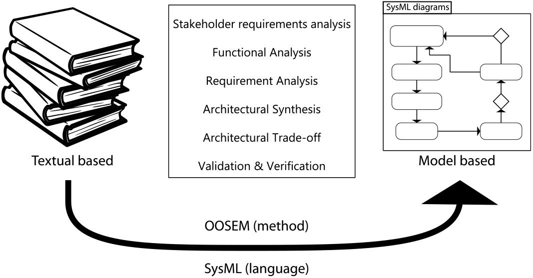
MBSE is often contrasted with a traditional textual-based approach to systems engineering (SE). In MBSE, the primary artefact of the system engineering process is the system model. On the other hand, in a textual-based system engineering approach, there is often considerable information generated about the system contained in textual documents. This information is often difficult to maintain and to assess in terms of its quality. In the MBSE paradigm, much of this information is captured in a system model as Fig. 2 shows.
Transition from SE to MBSE.

2.3 Object-oriented systems engineering method (OOSEM)
The Object-Oriented Systems Engineering Method (OOSEM) is a MBSE method that leverages object-oriented concepts and adopts SysML to facilitate the capture and analysis of requirements and design information to specify complex systems(Reference Friedenthal, Moore and Steiner17). OOSEM is usually applied recursively and interactively at each level of the system hierarchy, and it employs a top-down approach to specifying, analysing, verifying, design and development. In the Agile development philosophy, the system is incrementally constructed at each iteration, and OOSEM provides the flexibility to accommodate changing requirements and design evolution, making it an ideal method for this work, as long as it is tailored for Agile, as the INCOSE handbook(Reference Shortell11) remarks.
Analyse Stakeholder Needs
This activity supports analysis of both the as-is and the to-be enterprise. In OOSEM, an enterprise aggregates the system with other external systems that work together to accomplish the mission. The as-is systems and enterprise are captured in sufficient detail to understand their limitations and needed improvements. OOSEM specifies the requirements for the to-be enterprise to reflect stakeholder requirements which are statements reflecting stakeholder needs.
Analyse System Requirements
This activity generates system requirements associated with mission requirements. Usually, the system is modelled as a black-box that interacts with the external systems and agents. Use case diagrams are used to describe how the system should be used to accomplish the mission. These diagrams along with its context are used to derive functional, interface and performance requirements.
Define Logical Architecture
This activity decomposes the system into logical elements, defining the interactions between different elements within the system. These elements interact in order to satisfy system requirements (requirement analysis) and to capture system functionality (functional analysis). In this way, the requirements are allocated to corresponding functions. The establishment of a logical architecture helps mitigate the impact of changes on system design.
Synthesise Candidate Physical Architectures
In this activity, the logical elements are allocated to physical elements. A physical architecture describing the relations sups among physical system elements must be synthesised. Also, in this activity, the requirements associated with each physical element must be traced to system requirements.
Optimise and Evaluate Alternatives
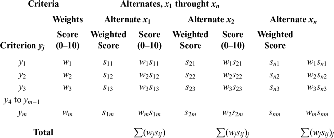
This activity consists of analysing and optimising the proposed architectures to the level of detail required to compare the alternatives proposed. Then, trade studies that can be traced to requirements are performed using criteria and weighting factors, potential risks are identified, along with technical performance measures (TPMs).
Manage Requirements Traceability
This activity is continuously performed to ensure traceability between requirements, system architecture, synthesis, analysis and validation elements.
Validate and Verify System
This activity comprises the validation of system requirements and the verification of system solutions. During this activity, the requirements database is continuously updated to trace the system requirements and design information to the system validation or verification methods and results.
2.4 Systems modelling language (SysML)
The Systems Modelling Language(18) (SysML) from the Object Management Group (OMG) has emerged from the Unified Modeling Language(19) (UML), the de facto standard for modelling in software engineering. Friedenthal(Reference Friedenthal, Moore and Steiner17) defines SysML as a general-purpose modelling language for systems engineering applications that supports the specification, analysis, design, validation and verification of systems and systems-of-systems. Each diagram is designed to represent a single aspect of the system of interest. The usage of each SysML diagram is briefly described as follows:
The behavioural aspect of the system is modelled using one or more of the following diagrams:
– Activity diagram (act) represents the workflow or a series of input to outputs relations of stepwise actions.
– Sequence diagrams (sd) describes interactions in terms of exchange messages between parts of the system in a time-wise fashion.
– State machine diagram (stm) describes the states of a system and its parts, and the events that trigger transitions between states.
– Use case diagrams (ucd) are used to describe the system functionalities and its relations to users and external agents.
Requirement diagram (req) captures text-based requirements and provides ease traceability between requirements, supporting the design, analysis and verification of elements in the model.
The system structure is modelled using block diagrams, which are divided into two types:
– Block definition diagram (bdd) shows how different elements are classified and describes the system hierarchy by decomposing the system in its elements.
– Internal block diagram (ibd) describes the relations between parts within the system and how they are interconnected.
The model is organised in packages on a package diagram (pkg). Each package may contain other elements, facilitating reuse and model navigation.
A parameter diagram (par) is used to impose constraints, such as mass, reliability and performance properties, among others, on the system, supporting engineering analysis.
SysML models systems aspects that may be classified into three groups: the behavioural aspect, its structure and its requirements, as shown in Fig. 3. The expression “SysML Taxonomy” in Fig. 3 denotes how the different types of diagrams are organised. Also, the reader is referred to Friedenthal(Reference Friedenthal, Moore and Steiner17) and to the SysML formal specifications(18) for a comprehensive reference on SysML.
Taxonomy of SysML.

3.0 SYSTEMS DEVELOPMENT WITH AMBSE
The last section presented AMBSE in general terms, not particularly focusing on its application in aircraft design and development. This section shows that not only AMBSE can enhance the conceptual design process, but that is also consistent with the Aerospace Recommended Practices ARP-4754A and ARP-4761 guidelines, as other methods(20) in the MBSE paradigm. It begins with a review of the Engineering Design Method which presents the concept of heuristics. This study of the engineering design method unravels the patterns normally encountered in the design process which not only facilitate the synthesis process but also makes information more accessible to communicate within a group. Then proceeds to an overview of ARP-4754A and ARP-4761 guideline indicating how they fit in AMBSE.
3.1 The engineering design method
The engineering design method is characterised by its iterative nature, in which the processes of analysis and synthesis are alternated until a feasible solution is found. In general, a solution is found when the proposed solution satisfies the requirements that are usually laid down in advance and continuously updated during the development cycle, as more information becomes available. The term “analysis” means in Greek “decompose into parts”. It is used in system engineering when applying principles or methods, usually mathematical, to problems or systems. Synthesis literally means “union, junction of parts”. It designates the act of bringing together related information to fit a technical purpose. The design progresses by the creation of hypothesis and conjectures in a process that is not necessary and sufficiently logical. This apparent deviation from the Scientific Method is necessary to solve any problem of practical nature by the deliberately use of heuristics. The term heuristics was used by Koen(Reference Koen21) in his studies on the Engineering Method to designate the way in which design engineers develop systems and products. Koen(Reference Koen22), defines heuristics in a very broad way as everything that helps to solve a problem, bringing it closer to its solution. In this sense, ansatz and ad hoc hypothesis are legitimate, as long as they are passive of validation, in the system engineering sense, specialty in the conceptual design, where data is often scarce. Among the most common heuristics, the following are particularly useful and formalised in System Engineering practice:
At the appropriate time, freeze the design
Allocate resources appropriate to the needs of each design phase
Allocate the necessary resources to the weakest link, in most cases, this heuristic can be replaced simply by analysing the worst case
Solve problems by successive approximations
In addition to that, one can infer that the sound practice of First Principles Design, using well-established theoretical results such as those found in Schlichting(Reference Schlichting and Truckenbrodt23), Ashley & Landhal(Reference Ashley and Landahl24), Kuethe(Reference Kuethe and Chow25), Kuchemann(Reference Kuchemann26), Hoerner(Reference Hoerner27, Reference Hoerner and Borst28), must be under consideration and fully integrated with the MBSE practice.
3.2 Unified mathematical modeling via bond graphs
Kypuros(Reference Kypuros29) describes bond graphs (BGs) as a graphical approach for diagramming the distribution and flow of power and energy within a dynamic system. Diston(Reference Diston30) made the first use of bond graphs in aircraft systems modelling. BGs were developed in 1959 by Dr Henry M. Paynter(Reference Paynter31) at MIT are used for modelling the storage, dissipation, transferring and transformation of energy within a dynamic system. In this modelling formalism, power, the rate of energy transfer between components, is taken as a fundamental quantity of physical systems and treated in the generalised form of a flow (f) and an effort (e). Since power is the “universal currency” of physical systems(Reference Gawthrop and Bevan32), bond graphing is, in fact, a unified multi-domain modelling approach. The graphical nature of bond graphs separates the system structure from the equations, making bond graphs ideal for visualising the essential characteristics of a system. In BGs, components energy ports are connected by bonds that specify the transfer of energy between system components(Reference Gawthrop and Bevan32). Moreover, the structure itself of the bond graph is designed to facilitate the systematic derivation of differential equations governing the dynamic response of the system model. Thus, bond graphs may be used not only to perform straightforward numerical analysis but to gain qualitative insight(Reference Gawthrop and Bevan32). The Appendix contains an introduction to bond graph modelling.
3.3 Overview of ARP-4754A
The document ARP-4754A(15) provides guidelines for the development cycle of aircraft systems, for the planning of the development process and guidelines for showing compliances with regulations. In general, aircraft systems show a high degree of interaction between systems. Thus, they have many modes of failure that affect the safety of the aircraft. ARP-4754A provides a methodology to mitigate development errors and provide a guideline for assigning the adequate assurance level that errors in the development cycle have been identified and corrected.
The typical system development progresses iteratively and concurrently using both top-down and bottom-up strategies. The top-down sequence prescribed in ARP 4754A for developing a system from intended function not only provides a conceptual model for system development but mirrors the AMBSE process tailored for aircraft design in this work. As part of this process, the system architecture evolves establishing the structure and boundaries within which specific item design is implemented to meet of the established safety and technical performance requirements(15). Moreover, the development planning guideline recognises and highlights the iterative nature of the design activity and the presence of interrelationships such as feedback loops during the development process. In practice, system architecture development and the allocation of requirements are tightly-coupled, where many candidate architectures are then evaluated using functional and performance analyses that establish feasibility in meeting the function and top-level safety requirements assigned to the system. With each iteration cycle, the identification and understanding of the requirements increases and the allocation of the system-level requirements to hardware or software items become clearer.
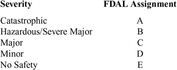
According to ARP-4754A, safety requirements are functionally decomposed from aircraft level to the item level in a hierarchical structure. The ARP-4754A guideline provides a rationale for development assurance level assignments considering the system complexity, and safety criticality embed in the system architecture. The Development Assurance Level assignment process begins with the Functional Development Assurance level (FDAL) assignment to the functions involved in the aircraft’s and/or systems’ functional hazard assessment (FHA) top-level failure conditions. An FDAL is assigned to the top-level function, based on its most severe top-evel failure condition classification under Table 1. In summary, AMBSE can support the process described in ARP-4754A from aircraft to item level by aligning checkpoints and reviews with program phases.

3.4 Overview of ARP-4761
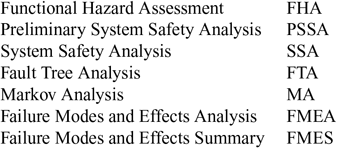
The document Guidelines and Methods for Conducting the Safety Assessment Process on Civil Airborne Systems and Equipment (ARP-4761(33)) provides guidelines and describes methods of performing the safety assessment of civil aircraft. These methods summarised in Table 2 are qualitative and can be qualitative(33) provide a systematic way to show compliance with FAR 25.1309. The ARP-4761 techniques presuppose that a functional analysis has been done and that associated hazards have been properly addressed. The safety assessment process begins with the concept design and derives the safety requirements for it. As the design evolves, changes are made, and the modified design must be reassessed. This reassessment may create new derived design requirements, which frequently necessitate further design changes. The safety assessment process ends with the verification that the design meets the safety requirements(33).

At the beginning of the development cycle, according to ARP-4761, it is convenient to identify and classify the failure condition(s) associated with the aircraft functions and combinations of aircraft functions. This is done with a functional hazard assessment (FHA) technique at the beginning of the development cycle. These failure conditions establish the safety objectives. After aircraft functions have been allocated to systems by the design processes, each system which integrates multiple aircraft functions should be re-examined using the FHA processes. The starting point of the Preliminary System Safety Assessment (PSSA) is the output of FHA. The PSSA is a systematic examination of the proposed system architecture(s) that is conducted at multiple stages of the system to determine how failures can cause the functional hazards identified by the FHA. The PSSA should also establish protective strategies and architectural features necessary to meet safety objectives. The result of the PSSA is intended to identify hardware failure effects, development error effects or hardware and software, reliability budget, and development assurance levels.
AMBSE benefits from the use of ARP-4754A and ARP-4761 practices (see Fig. 1), since these technical standards imposes design discipline and development structure, ensuring that both operational and safety requirements are fully realized and substantiated. Also, AMBSE facilitates the use of these practices by providing a design environment where requirements and solutions evolve by small verifiable increments through collaboration between self-organizing cross-functional teams and end users.
4.0 APPLICATION OF AMBSE IN CONCEPTUAL DESIGN
This section presents the application of AMBSE to the first design iterations during the conceptual design phase. AMBSE is applied to both the aircraft, system, and component level following the process described in Fig. 1. The component level is used to illustrate how AMBSE may support the so-called Post-Tier 1(Reference Michaels34) supply chain trend, which involves more vertical integration and restructured responsibilities between OEM and its suppliers. AMBSE supports an approach in which the aircraft designer is aware of the interactions and implications between systems and different disciplines. This is especially important in conceptual design, which is an intense exploratory phase due to its iterative process structure, involving feedback loops and successive refinements. Also, the emphasis on the practice of first principles design within AMBSE results in rapid design-responses, allowing requirements and solutions to gradually develop through collaboration between cross-functional teams and end users, as prescribed by the Agile philosophy.
Section 4.1 describes the required tools and how to organise the model in the modelling environment. Section 4.2 to Section 4.4 illustrates the AMBSE process to the aircraft level. Section 4.5 describes the first steps of the process of architecture synthesis and analysis focusing on the flight control system and associated systems. Finally, the chapter ends with a discussion of the limitations of the current implementation, of the pros and cons of AMBSE, and prospects for future research work.
4.1 Design methods & tools
The AMBSE process described in Section 2.1 and shown in Fig. 1 is represented as a SysML activity diagram in Fig. 4. The activity box inside the diagram describes the system engineering activities. After the specific system/subsystem architecture is analysed/synthesised, it is compared with alternative proposals. Once a candidate architecture is considered sufficient mature for the present purposes, it is passed to Integrated Product Development Teams (IPDTs) for preliminary design. The standards ARP-4754A and ARP-4761 are used to requirements generation during the entire process.
AMBSE delivery process during conceptual design phase.

AMBSE requires an integrated development environment (IDE). In this work, Eclipse(35) Papyrus(36) was chosen because it is open-source, offers UML/SysML modelling capabilities and it contains an extensible plug-in system for customising the environment. In particular, Papyrus was augmented with Massif(37) and Epsilon(38) plug-ins, allowing to transfer SysML activity diagrams to subsystem blocks in the Simulink environment. Engineering analysis necessitates the creation of dynamic models. As mentioned in Section 3.2, the use of the object-oriented paradigm with bond graph modelling can facilitate the process of deriving the necessary differential equations. The software 20-sim(39) was used in this work to model systems with the bond graph formalism and also to generate the respective s-functions, which can promptly be used in a Simulink model with great numerical computational performance.
Microsoft© Excel™ is used as a technical calculation and report creation tool, since it is nearly universally used across the world and because its negative aspects can be managed. All of the spreadsheets, conforming to the same format and layout. The traditional design approach as in Roskam(Reference Roskam40), Nicolai(Reference Nicolai and Carichner41), Datcom(Reference Hoak and Ellison42), Kuchemann(Reference Kuchemann26), Dubbel(Reference Dubbel and Davies43) and Hoerner(Reference Hoerner27, Reference Hoerner and Borst28) was implemented in a spreadsheet customised with XL-Viking(44) plug-in. Most of the spreadsheets use the XL-Viking Add-in to display and audit the calculations. The XL-Viking add-in contains easy to use functions that show all the numbers or variables in each Excel formula. This ensures accuracy and traceability of the calculations, allowing significant and valuable time is saved in checking and auditing of calculations while keeping all of the calculations live and writing and updating reports is much quicker and easier. This feature also facilitates the use of conceptual development and design-related analytical tools (such as risk assessment matrix and sensitivity analysis), described in Goldberg et al(Reference Goldberg, Everhart, Stevens, Babbitt III, Clemens and Stout45). This spreadsheet approach allows Python scripting through XL-Wings(46) plug-in to facilitate the data transferring to the Simulink environment and to generate input to the SUAVE conceptual level aircraft design environment. The design environment SUAVE(Reference MacDonald, Clarke, Botero, Vegh and Alonso47) was used to both aerodynamic and performance analyses. The plug-in gendoc(48) is used in the Eclipse environment to generate word files containing the corresponding diagrams. Recurrent engineering calculations were also inserted in the generated documents.
Model Organisation
A fundamental step previous to initiating the modelling process is to establish modelling conventions and standards. The OOSEM method prescribes how to organise the model using a package structure. The package diagram in Fig. 5 describes the model organisation adopted. The model organisation is a hierarchical package structure that mirrors the system hierarchy in terms of system, element, and component levels. Each of the packages contains model elements for the next level of decomposition of the block, including its structure and behaviour that are created by applying OOSEM to the specification and design of the system. The model organisation also includes other packages that are not nested within the system hierarchy packages. These packages contain their own hierarchy consisting of nested packages, which may not correspond directly to the system hierarchy. However, both are linked in order to ease the navigation of the model by the use of hyperlinks a to the diagrams of interest. In this way, it is possible for a designer to keep the design, for instance, of the flight control system without losing sight of the overall hierarchical structure which numbered according to the Joint Aircraft System/Component(Reference Monroney49) (JASC) code system.
Model organisation.

4.2 System requirements analysis
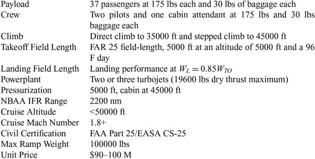
The AMBSE approach was applied in the design of a hypothetical aircraft designated as Kr-206 which is intended to provide ways to test and develop advanced design techniques and methodologies. In particular, supersonic transport (SST) aircraft design demands special attention to the flight control system, where many factors differ significantly from subsonic aircraft. Some of these factors are related to the following: Handling qualities, control surfaces layout, artificial stability augmentation, actuator technologies and sensitivity to engine placement. Most of the stakeholder requirements were inferred from technical literature(Reference Wolf50–Reference Smith52), except the range requirements, and are shown in Table 3. The reason for such a low range requirement for a SST is explained by two facts: first, it is known that the energy in the compression wave primary depends, among other things, on the speed of the aircraft, the physical size & the weight of the aircraft. It was then reasoned that a first prototype conceptual aircraft ideally should be the smallest as possible. A compromise between market, technical and research requirements was found to to be 2200 nautical miles. AMBSE supports requirement management through the use of SysML requirement diagrams. Since one of the desired outcomes of the AMBSE is to facilitate change of requirements, the aircraft will eventually be redesigned for 4200 nm with an improved set of market and stakeholder requirements. It is worthwhile to mention that the data contained in this work have illustrative purposes and therefore should not be used as a basis for other designs. The hypothetical aircraft is to be certified under FAR Part 25(12)/EASA CS-25(53) and is also subject to noise requirements.
Request for proposal - supersonic Jet

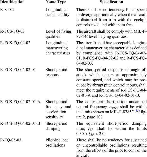
The regulation FAA Part 25/EASA CS-25 does not establishes flying qualities criteria. However, the document flight control design best practices(54) recommends that the MIL-F-8785C(Reference Moorhouse and Woodcock55) should be followed as a guide for the flying qualities criteria. The Table 4 shows a partial list of the requirements gathered from both Part 25/CS-25 and MIL-F-8785C.
Partial list of longitudinal flying qualities requirements

4.3 Functional analysis
The purpose of this activity in the systems engineering process is to iteratively identify the functions that the system must perform. Functional analysis is essential to the application of ARP-4754A/ARP-4761 standards, because of that in the methodology followed in this work, it is given a specific phase in the process. This activity establishes basic aircraft level performance, and operational requirements, which is accomplished by arranging the functions into logical sequences, decomposing top-level functions into lower-level functions, and allocating performance requirements generated from the higher-level functions in the hierarchy to the lower-level ones. The output of this process is the functional architecture of the system, that is, a description of the system, regarding its functionality. According to ARP-4754A(15), the output of this activity is a list of aircraft level functions and associated function requirements and interfaces for these functions. In AMBSE, it is a diagram as shown in Fig. 6.
Top-level functional analysis.

4.4 Logical architecture definition
The logical architecture establishes the structure and boundaries within which specific system design are implemented to meet all of the established safety and technical requirements. In practice, this the logical architecture definition phase, requirement and analysis functional and the allocation of requirements are tightly coupled iteratively processes. Since functional and performance requirements originate at the highest levels of the system hierarchy, these activities must be continuously repeated to define the logical architecture at ever greater levels of detail. This process generates many types of requirements which include: independence, probabilistic, qualitative, availability, integrity, monitoring, operational and maintenance requirements and in later iterations Function Development Assurance Level (FDAL). Moreover, ARP4754A(15) states that the hierarchical safety requirements are generated by safety analyses by functionally decomposing from aircraft level function to the item level. In this process, it is convenient to add a SysML stereotype to each requirement marking its type.
At the aircraft level, the safety requirements are generated from the aircraft FHA based on top-level aircraft functions previously defined, as in 4.3. At the system level, the safety requirements are all those system level requirements generated from the system FHA which are decompositions of the aircraft level safety requirements. At the next level down the requirements are all those aspects of the system which allow the safety objectives associated with the system FHA classifications to be satisfied. The output of this process generates many elements which need to be organised via SysML packages. In addition to that, the present work adopted the JASC(Reference Monroney49) code tables, as shown in Fig. 7. The JASC numbering provides a consistent framework for the aircraft technical documents. At the item (component and subcomponent) level, S1000D(56) were used. It is worth mentioning that each block in Fig. 7 contains a hyperlink to another block diagram describing its respective hierarchy.
Logical decomposition with JASC code.

The process of allocating requirement to functions is initially performed by use case diagrams (ucd) (see Figs. 8 and 9). The requirements were gathered in the requirement analysis activity and were decompose into smaller, more manageable requirements, using requirement diagrams (not shown). These requirements are then allocated to the top-level functions identified in the functional analysis (Section 4.3) activity.
Use case diagram allocating requirements to the function Provide Stability.

Use case diagram allocating requirements to the function Perform Flight Control.

The function “provide stability & control” in Fig. 8 is the most top-level aircraft function related to the stability and control of the aircraft. Each requirement element contains a hyperlink to the corresponding requirement packages, where requirements are organized in a hierarchy according to its type.
The function “Perform Flight Control”, in Fig. 9, is associated with the flight control system (FCS). The FCS contains interfaces to many systems, for instance, the hydraulic and the electric power system. Moreover, in this specific project, it was detected that the supersonic longitudinal stability depends greatly on the center of gravity. Therefore, it is necessary to include a interface to the fuel system, as well. In order to facilitate the design process while managing all the mentioned systems, it was necessary to create a System Breakdown Structure (SBS) diagram (not shown). Essentially, the SBS contains elements typically associated with different JASC numbers. In the AMBSE approach, the SBS is connected to the system logical architecture by hyperlinks, allowing the designer to focus on the particular system design of interest.
4.5 Architecture synthesis and analysis
The activity architecture synthesis and analysis comprises the allocation of functionality and corresponding different kinds of requirements to high-level physical elements. Ideally, more than one candidate system architecture should be considered in this activity. These candidate architectures are then iteratively evaluated using functional and performance analysis, which generate Figures of merit (FoMs) or technical performance measurements (TPMs) that are to be used in the architecture trade-off phase. In later iterations, when the candidate architecture contains sufficient detail, it is possible to apply preliminary phase ARP-4761(33) Preliminary Aircraft Safety Assessment (PASA)/Preliminary System Safety Assessment (PSSA) processes to establish the feasibility in meeting aircraft and functionality and top-level safety requirements assigned to the system.
Aircraft Level
The hypothetical aircraft development in this work features a double cranked-arrow wing. A feature of this wing is that its aerodynamic centre shifts as the Mach number increases, moving towards the tail cone of the aircraft(Reference Stengel57). A major penalty of this type of wing is that the drag increases due to the required deflection of the control surfaces needed to compensate an aircraft, in transonic regime. In the supersonic regime, this penalty is even greater, and the stability of the phugoid mode is often reduced. In such cases, it is desired to move the Center of Gravity during flight, which can be accomplished by integrating the fuel system with the flight control system. By transferring fuel, it is possible to maintain the static margin during transonic and supersonic regime to only 3% of the mean aerodynamic chord. This feature highlights the benefit of early systems integration in conceptual design that AMBSE makes possible and manageable. The aircraft level AMBSE is discussed in Sections 4.2–4.4.
System Level
In the conceptual design, it was decided that the aircraft shall not have a horizontal stabiliser in order to improve its aerodynamic performance. Thus it requires a fly-by-wire system to augment its longitudinal stability characteristics. Ideally, an optimal system architecture was developed that would meet regulatory compliance for system safety(15, 33) given constraints such as cost, weight, envelope, and complexity. For the present purposes, the primary driver considered in the conceptual design phase of the fly-by-wire system is the system safety. The design options normally include duplex, triplex, quadruplex control channel redundancy and various combinations of electrical, mechanical, or hydraulic connections. The safety analysis tools used are those prescribed in the System engineering toolbox for design-oriented engineers (Reference Goldberg, Everhart, Stevens, Babbitt III, Clemens and Stout45) and in the ARP guidelines, namely, the Functional Hazard Assessment (FHA) and Fault Tree Analysis (FTA) (see Sections 3.3 and 3.4). It is worthwhile mentioning that the FHA is a living document throughout the design development cycle(33), which is also desirable for the AMBSE.
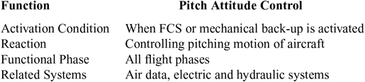
The design usually starts with the functional analysis described in Section 4.3. Then, the designer/analyst must begin with an undesired top level hazard event, classified according to Table 1, and systematically determines all faults and failure combinations of the system functional blocks up to the next lower level in the system hierarchy, which could lead to this event. In the conceptual design, often it is possible to omit some items or components which are considered non-essential for the analysis purposes. In this work, for instance, it was assumed that the reliability of mechanical components is high enough to be omitted in the first FTA analysis of the FCS. For illustrating purposes, the function “Control Pitch” in Fig. 4.3 is chosen for the FHA/FTA process and defined in Table 5.
Definition of the Pitch attitude control function

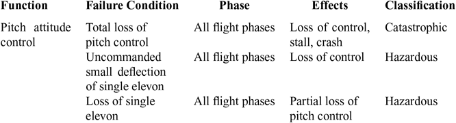
For illustrating purposes, two different initial architectures are proposed for the FCS consisting of Flight Control Computer (FCC) electrical lanes that interface with Electro-Hydrostatic Actuators (EHA) located on the outer and inner sections of the wing. The system concept designs evaluated involved traditional and hybrid architectural schemes for functional redundancy and operation. Both architectures share the same philosophy in which all primary flight control surfaces are all electrically controlled and hydraulic activated – the FCS interfaces with hydraulic and electrical systems. The actuators are powered by the aircraft blue, green and yellow hydraulic lines. Four elevons control the nose up and down movement. The safety objective that both architectures are to be measured against is that the probability for a catastrophic event(15) shall be less than  $ 1\times10^{-9} $ (see Table 1). Table 6 contains an initial Functional hazard Analysis (FHA) for the pitch control function.
partial list of FHA results for the function pitch rolling attitude control

The first architecture proposed is denominated Tri-Tri and consists of four electrohydrostatic actuators (EHA) and four electrically signaled hydraulic actuators fed by two of three independent hydraulic systems and controlled through three (tri) independent electrical systems that communicates through three (tri) electrical control lanes partitioned among four different FCCs. Each hydraulic system (Blue/Green/Yellow) is associated with three electrical lanes. In this architecture FCC #1 and FCC #2 are dedicated to the hydraulic system Blue, while FCC #3 and FCC #4 are dedicated to hydraulic system Green. This architecture has the disadvantage that if one FCC fails, the system only two faults away from a catastrophic hazard. In this scenario, the other FCC on the same hydraulic system may fail together with the backup hydraulic system.
The second architecture proposed is denominated Dual-Quad and consists of four electrohydrostatic actuators (EHA) and four electrically signaled hydraulic actuators also fed by two independent hydraulic systems. The flight control surfaces are powered by a combination of hydraulic and electro-hydrostatic actuators. For each elevon system there are two (dual) independent electrical systems communicating through four (quad) electrical lanes. It is assumed that the FCS possess by three primary computers and two secondary computers that process pilots and autopilots inputs according to normal, alternate or direct flight control laws.
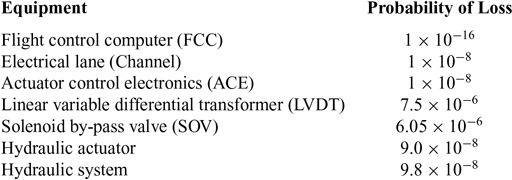
The FHA is the input for the Fault Tree Analysis (FTA) (Fig. 10), along with the assumed probability of loss used in the FTA process are shown in Table 7. As mentioned in Section 3.4, both are required by ARP4754A(15). Also, the probability of loss for mechanical and electrical components can be found in Dhillon(Reference Dhillon58), MIL-HDBK-217F(59), and Schafer(Reference Schafer, Angus, Finkelstein, Yerasi and Fulton60).
Initial fault tree analysis for the FCS.

Assumed probability of loss

All failure rate probabilities are per flight hour
These figures are for illustrative purposes only
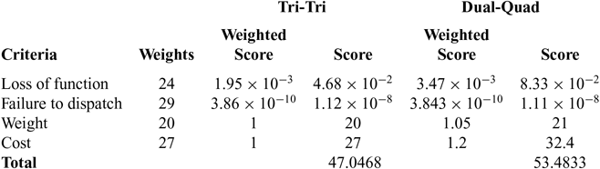
The results for the FTA realised for both architectures, Tri-Tri and Dual-Quad are in Table 8. Figure 10 shows the FTA diagram used to estimate the Loss of Function (LOF) and Failure to Dispatch (FTD) probability. Both candidate-architectures satisfy the ARP 4754A requirements for the probability of a catastrophic event to be be less than  $ 1\times10^{-9} $. As Table 8 shows, the architecture Tri-Tri is taken as the baseline for the weight and cost criteria, which were estimated according to Roskam(Reference Roskam40) and Nicolai(Reference Nicolai and Carichner41).
Fault tree analysis for the FCS architectures

These figures are for illustrative purposes only
At this point, it is desirable to use a multicriteria analysis employing a pairwise comparison process, in that way, it is possible to compare options and factors in a relative manner. In this work, the Analytical Hierarchy Process(Reference Goldberg, Everhart, Stevens, Babbitt III, Clemens and Stout45) (AHP) was chosen in the selection of the best architecture for the present conceptual purposes. The results are shown in Table 9 (see also Appendix C). This approach combines the subjective with the rationale assessment of each of the proposed alternatives. The architecture Dual-Quad scored higher than the Tri-Tri architecture and thus it was selected for further development.
Trade-off for the FCS initial architecture

The selected architecture schematics shown in Fig. 11. From it, it is possible to consistently derive its corresponding bond graph by substituting each identified system by a word bond graph. A SysML block definition diagram is drawn to represent its structure and interfaces with associated functions and requirements. Each element, represented by an word bond graph, in the architecture is then modelled as a bond graph using the software 20-Sim(39). This software is capable of exporting the bond graph model and its sub-models as s-functions, which can readily be integrated into the Simulink model and runs faster than native Simulink blocks.
Proposed initial flight control system architecture.

The same safety process used in the conceptual development of the FCS was repeated for the fuel system. Figure 12 shows the selected architecture for the fuel system in the conceptual design. It was designed to provide data for the total fuel volume required, the size, location and number of fuel tanks needed and the number of fuel pumps, its location and the required capacity of fuel pumps and fuel lines. The engine fuel flow was obtained in this stage by multiplying the maximum required thrust by the associated fuel consumption. Although it is reasonable to assume that the number of tanks in order to keep the cost to a minimum and reduce weight, in this work, the size, location and number of tanks were driven by stability requirements concerning the desired location of Center of Gravity for different loading scenarios. The sizing of fuel lines and the determination of necessary fuel pump pressures were calculates using Marks’ Standard Handbook for Mechanical Engineers(Reference Avallone, Baumeister and Sadegh61). The simple schematics in Fig. 12 along with first principle calculations was sufficient to generate a bond graph representation, which was included in the Simulink model as an s-function.
Proposed initial fuel system architecture.

Component Level
As shown in Fig. 11, the selected FCS architecture employs four Electro-Hydrostatic Actuator (EHA) and three Electro-backup-Hydraulic Actuator (EBHA). The design of an EHA (see Fig. 13) requires multi-domain modelling capability since on it mechanical, hydraulic, thermal and electrical domains interact with each other. Therefore, bond graphs are an ideal tool for modelling such components. In this work, for conceptual design purposes, the following EHA components (or subcomponents) are considered: Electrical motor, hydraulic pump, accumulator, associated hydraulics (two valves and a bypass valve), hydraulic cylinder, the mechanical actuation (four-bar mechanism) and control surface.
EHA schematics.

Following Langlois et al(Reference Langlois, Roboam, Maré, Piquet and Gandanegara62), the EHA system comprises an electrical, a mechanical and a hydraulic part. The electrical part of the EHA is a servo-valve which controls the fluid dynamics inside the chambers. The spool valve is driven by the electrical input current of a torque motor. It is assumed that the EHA is supplied with a constant DC voltage source. In practice, the EHA is fed with a three-phase AC power that supplies power drive electronics, which in turn, drive a variable speed pump together with a constant displacement hydraulic pump(Reference Moir and Seabridge63).
Figure 14 shows the initial SysML diagram for the EHA schematics in the Fig. 13. It consists of a block definition diagram (bdd), where requirements are allocated to each block, representing physical components.
Initial SysML diagram of EHA.

As briefly mentioned in the Section 2.1, BGs may be used in an object-oriented(Reference Borutzky14) way, which also provides a means for the straightforward conversion of the bdd (Fig. 14) into a word bond graph. Figure 15 shows the word bond graph, created in the software 20-sim(39), based on the schematics of the EHA shown in Fig. 13. Each word bond graph is further modelled separately and then integrated into one bond graph, which will be exported as an s-function.
word bond graph for the elevon-actuator assembly.

In this way, BGs facilitates the integration of components, for instance, the elevon. At this stage, the elevon can be modelled by a second-order mechanical equation, which corresponds in the Bond Graph formalism to a 1-junction connected to -R, -I and -C elements. Its physical connection with the EHA is modelled by a transformations element, in this case, a transformer (TF) element. The resulting bond graph with the integration of the control surface (elevon) is shown in Fig. 16.
Integration of the control surface with the EHA.

As mentioned above in this section, the solution for longitudinal instability in the supersonic regime involves both the FCS (through the use of a control law) and the fuel system (in order to transfer fuel to achieve the desired center of gravity). Both systems were modelled, and the corresponding s-functions were exported from 20-sim to be integrated into the Simulink “master-model”, depicted in a simplified way in Fig. 17.
Simulink master-model with fuel system and EHA.

The master-model is a six-degree-flight dynamics (see Appendix A) model describing the dynamics of the aircraft that contains every physical element previously modelled along with a control law and a manoeuvre generator. The manoeuvre generator is capable of prescribing a trajectory that the aircraft must follow. In this way, it is possible to analyse the aircraft dynamic behaviour in order to satisfy the requirements. A disadvantage of this approach is the time that is required to evaluate each requirement. However, this can be mitigated by the use of s-functions which tend to be run faster and are easily generated from BGs with the 20-sim software.
Partial list servo-actuator specifications

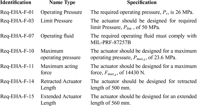
Table 10 presents a partial list of servo-actuator specifications deduced from the AMBSE approach. They were generated from the complete bond graph model where its nominal parameters were calculated using standard mechanical engineering methods that were programmed into design spreadsheets. The complete list has 30 requirements, including performance and functional requirements and it is intended to complement and foster discussion with stakeholders and suppliers.
4.6 Validation and verification
Validation and verification comprise independent procedures that are used together for checking that the system meets its intended functions, its requirements and specifications. In the present work, both procedures are realised in MATLAB/Simulink in a six-degree-of-freedom flight dynamics model. A brief discussion of this model and control laws are contained in the Appendix. The requirements pilot-induced oscillations, short-period damping, short-period frequency and acceleration sensitivity (presented at Table 4) were validated and verified using the flight dynamics model in Simulink. Thus the system satisfies the short-period response. It is worthwhile to note that the terms “validation and verification” used in the conceptual design denotes a design strategy and it is not intended to mean that the system is ready for certification.
The longitudinal response to an elevon step command for the non-augmented aircraft is shown in Fig. 18. It must be noted that without augmentation the aircraft is inherently unstable in the longitudinal mode. The longitudinal behaviour of the aircraft using the dynamics inversion control law is shown in Fig. 19. Using flight control augmentation through the use of dynamic inversion control law,  $ {{\omega }_{SP}} $ becomes 2.05 rad/s and the short-period damping ratio,
 $ {{\zeta }_{SP}} $, becomes 0.79.
Non-augmented longitudinal response.

Inversion dynamics.

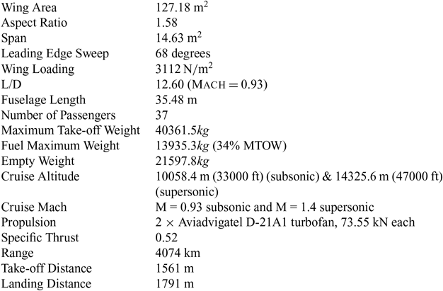
The aircraft conceptual design specification at this stage is shown in Table 11 and the side and the top-view of the hypothetical aircraft Kr-206 are shown in Fig. 20. Subsequently, iterations are necessary to improve the conceptual design further. A related point to consider is the influence of the aircraft configuration on system architecting. The current AMBSE framework is not capable of determining the existing physical constrains associated with the Outer Mold Line (OML) of the aircraft under design.
Kr-206-A specifications

aThis values correspond to the first iterations and therefore should not be used as a basis in any design
Hypothetical aircraft designed using AMBSE (dimensions in feet).

4.7 Limitations of the current implementation
It should be noted that, the current AMBSE implementation has some limitations. First, there is no clearly defined baseline to compare the effectiveness of AMBSE versus the traditional approach. Because most of the advantages of Agile methods (over the more traditional approaches) rely upon the more efficient team management schemes, it is, currently, difficult to draw a satisfactory conclusion based solely on the current implementation of AMBSE. In addition to that, the design information is dispersed among different softwares, making it difficult for sharing in a more consistent way within a team. Ideally, all the design information and its requirements should be recorded in a database easily accessible by concurrent teams. Additionally, the tool-chain is not stable enough for more comprehensive design explorations.
Also, the current design work mostly relies on design data that is supplied by traditional weight estimation methods as in the conventional approaches. This adds a limiting factor to the current AMBSE framework that restricts its application to the design of conventional and more understood aircraft. During the conceptual design phase, many design interactions are performed in the OML of the given configuration under study. Another key limitation is the fact that some necessary design tools were incorporated into the AMBSE tool-chain, for instance, the computer aided design tool used to define the aircraft. Section 4.9 provides some ideas to improve future implementations of AMBSE in these aspects.
4.8 Discussion and Pros & Cons of AMBSE
The purpose of the safety assessment (SA) process is to identify and evaluate potential hazards related to the aircraft regardless of the details of its design and to establish the safety objectives for aircraft functions to achieve a safe design. AMBSE allow a smooth transition from conceptual to preliminary design because the design information captured by SysML diagrams are readily available for the SA process required by ARP-4754A and ARP-4761 during the preliminary design phase.
AMBSE facilitates advances for novel aircraft because they are characterised by the more integrated use of systems. The properties of bond graphs make possible to model multidisciplinary systems, not only EHA mentioned in the text, but also, fuel cells(Reference Saisset, Fontes, Turpin and Astier65, Reference Chan, Bouscayrol and Chen66), and jet turbine engines(Reference Shoureshi, Herrick and Brackney67) in an integrated way. While standard modelling approaches have often been used in aerospace practice, bond graph modelling allows a better understanding of the interaction between the subsystems. Also, the nature of bond graphs facilitates the design exploration of the subsystem/component itself such as the EHA described in this work. In this manner, the rework that is necessary in order to satisfy requirements, especially safety requirements, usually realised in the preliminary design phase will be validated at in the conceptual design phase. In this case, the preliminary design phase will be mostly concerned with verification of safety requirements.
AMBSE has the advantage of generating better requirements. It also improves communication among development stakeholders. The design information may be captured with SysML diagrams, which increases the ability to manage the complexity within a project. These same models might be used again to enhanced knowledge capture and reuse of information. Therefore, care must be taken to ensure the consistency between models. However, as the project develops in complexity, the workload increases at each step. Also, there is the risk of focusing too early on detail and/or to exclude less understood concepts too soon. Nonetheless, this risk might be compensated by the ease with which models can be tested in AMBSE. In addition to that, the computational nature of AMBSE facilitates the creation of a model library containing validated models draw from the literature or derived through system identification(Reference Jategaonkar68).
4.9 Prospects for future research
Future research is concerned with the development of a AMBSE software tool in order to mitigate many issues pointed out in Section 4.7 and 4.8. In this tool, the design information is recorded in the Extensible Markup Language (XML), which allows many designers to access, edit and review the project in a similar way to existent software management tools such as GitHub(69). The fundamental idea underlying this design tool is to combine bond graph models and SysML models, leveraging the concept of object orientation. Each element in system hierarchy and its properties will be computationally represented by an object instantiated by a general class that can be manipulated through scripting at the designers will. It is a known fact, in computer science, that Category Theory(Reference Simmons70) concepts are closely related to functional programming languages(Reference Michaelson71). Thus, future research will be dedicated to develop a bond graph based metamodel(Reference Gawthrop and Smith72), framed within the mathematical Category Theory(Reference Mabrok and Ryan73) and coded in a functional programming language (e.g. Haskell(Reference Marlow74)) in order to automate the cumbersome task of manually checking the consistency of SysML models. This metamodel suggests the possibility of the use of formal methods to each validation and verification cycle. Bond graphs possess some interesting extensions(Reference Margetts75, Reference Maia Neto and Goes76), allowing many different multidisciplinary systems to be not only modelled but tested and its global performance impact measured during the conceptual design phase. Also, it is worth mentioning that the BGs work well with optimisation(Reference Gawthrop77) and sensitivity studies(Reference Gawthrop78). These characteristics possess obvious advantages to investigate novel concepts such as more-electric aircraft, more-electric engine, distributed (electric) propulsion and so on, that inherently depend on the integration of multidisciplinary systems. Therefore, future investigations will also focus on the integration of the recent advances in multidisciplinary robust optimisation into the AMBSE framework, which should also include BG optimisation, enabling the design of novel aircraft systems, where surrogate models will be used where required to provide the necessary information for the design space. It is worthwhile mentioning, in passing, that many system safety assessment techniques such as FTA used in the work are suited to be modelled by bi-graphs (directed graphs), allowing the possibility of combining modelling and simulation of components with its reliability aspects. It is expected that this technology will evolve into a new class of SoS analysis techniques suited for analysing the impact and feasibility of new technologies at the conceptual stage while enabling the system architect to navigate smoothly and continuously through the requirements, functional, logical and physical views of the evolving architecture. Lastly, future work will demonstrate the effectiveness of AMBSE by actually employing cross-functional teams interacting with customers in a realistic industrial design environment.
5.0 CONCLUSIONS AND FUTURE PERSPECTIVES
This paper demonstrated the use of the Agile philosophy in the aircraft conceptual design. The design of the flight control system is selected to illustrate the procedure in detail, and it is concluded that AMBSE presents promising properties to support future aircraft development within the current regulatory framework for aircraft design, while enabling a smooth transition from conceptual to preliminary design. It is shown that verifiable models are required for agile systems engineering to enable design studies across all disciplines and constraints. OOSEM and SysML provide the flexibility to accommodate changing requirements and design evolution, making them good candidates for modelling within the Agile philosophy. This not only ensures that at the end of each iteration, the maturing system design meets the requirements from early on but guaranties later a smooth transition from conceptual to preliminary design. The mathematical models necessary to develop the verifiable models in Simulink can be easily derived from the bond graph approach. Moreover, bond graph models used in an object-oriented way harmonise with the methodology described and can be used by engineers to perform straightforward numerical analysis, in addition to gaining qualitative insight, aiding the designer especially in the early stages of design and integration. The common spreadsheet approach enhanced with add-ins is capable of ensuring the accuracy and the traceability of the initial parameters calculations. The combination of mathematical modelling, safety assessment and system design techniques provide valuable insights into the conceptual design process, especially when applied to lower level aircraft systems. Within the Agile philosophy, the engineering experience and creativity still remains the essential keys to the successful development of the system.
There are many interesting extensions to this effort that may be considered as future work. Most obviously, it is of interest to continue this work by expanding to other major aircraft subsystems, namely: fuel, engine control, hydraulic, electrical power generation and landing gear systems. On-going research aims to develop a rapid multidisciplinary optimisation strategy to improve its general handling qualities under given design constraints. This improvement in the early design will facilitate the selection of the initial change-friendly baseline required for incremental development, presupposed by the Agile philosophy. Future research will focus on the development of a theoretical metamodel comprising structural, behavioural and requirements aspects, along with time-continuous parametrics, based on the bond graph formalism. This will lead eventually to a software implementation featuring a graphical user interface tailored for Agile systems and concurrent engineering. In principle, this framework should be easily extended to related fields.
Appendix
A - FLIGHT DYNAMICS MODEL
The six-degree-flight dynamics model developed describes the dynamics of the aircraft by six equations and includes three additional equations ( $\dot{V}$,
 $\dot{\gamma}$ and
 $\dot{\chi}$) governing the direction and magnitude of the velocity vector. They are derived by solving all the forces acting on the aircraft into three directions. It is also assumed that there are no propulsive forces and flat earth approximation. The variables V, γ and χ represent the aircraft speed, its flight path and heading, respectively. In practice, their rates are typically input by the pilot or by the flight computers. The remaining variables (
 $\dot{u}$,
 $\dot{v}$,
 $\dot{w}$,
 $\dot{p}$,
 $\dot{q}$,
 $\dot{r}$,
 $\dot{\theta}$ and
 $\dot{\phi}$) correspond to rates of change in the x, y, z-axis, roll, pitch, yaw, pitch and roll angle, respectively. It is worth mentioning that the complete dataset of aerodynamic derivatives were calculated using AVL(Reference Drela and Youngren80). For supersonic estimations, the DATCOM handbook(Reference Hoak and Ellison42) was used, since digital datcom(Reference Vukelich and Williams81) is uncapable of handing very low aspect ratio wings.
Dynamic inversion control law
The synthesis of the dynamic inversion control law follows the approach developed by Snell(Reference Snell, Nns and Arrard79), in which the dynamics is divided in two groups: fast and slow dynamics. The former correspond to the states p, q and r, which are actuated by the elevons and the rudder and controlled by the fast-state controller. The remaining α, β and μ are controlled by a second, separated controller that executes the inversion dynamics using p, q and r as inputs. The motivation in adopting this approach is the assumption that the rapid transient dynamics of the fast states (p, q and r) have negligible effect on the slow states (α, β, μ) in the open-loop plant.
Control loop for p, q and r
The fast-dynamics employs the following equations(Reference Snell, Nns and Arrard79) (A.1, A.2, A.3) in a loop to achieve the desired value:
 \begin{equation}
\dot{p} = \omega_p \cdot \left (p_{cmd} - p \right )
\label{eqn1}
\end{equation}
 \begin{equation}
\dot{q} = \omega_q \cdot \left (q_{cmd} - q \right )
\label{eqn2}
\end{equation}
 \begin{equation}
\dot{r} = \omega_r \cdot \left (r_{cmd} - r \right )
\label{eqn3}
\end{equation}
The bandwidths  $ \omega_p $,
 $ \omega_q $ and
 $ \omega_r $ were set at 10 rad/s, following Snell(Reference Snell, Nns and Arrard79).
Control loop for α, β and μ
For the the design of the control laws for the slow dynamics (β, α and μ) it is assumed that the fast states (p, q and r) track their slowly changing commands exactly(Reference Snell, Nns and Arrard79). Moreover, it is assumed that the transient dynamics of the fast states occur so quickly that they have negligible effect on the slow states. This is a reasonable approximation for civil jets. Since β, α and μ are heaviliy dependent on p, q and r, the commanded values of p, q, and r are used as the inputs in the slow-state control law(Reference Snell, Nns and Arrard79). Following Snell(Reference Snell, Nns and Arrard79) the desired  $\dot{\beta}$,
 $\dot{\alpha}$ and
 $\dot{\mu}$ are specified by the following closed-loop dynamics:
 \begin{equation}
\dot{\beta_d} = \omega_{\beta} \left ( \beta_c - \beta \right)
\label{eqn4}
\end{equation}
 \begin{equation}
\dot{\alpha_d} = \omega_{\alpha} \left ( \alpha_c - \alpha \right)
\label{eqn5}
\end{equation}
Differing from Snell, the following transfer function was used for the the closed-loop dynamics of bank angle rate ( $\dot{\mu}$):
 \begin{equation}
\dot{\mu_d} = \frac{1.98}{s + 2.24} \dot{\mu_c}
\label{eqn6}
\end{equation}
As discussed by Snell(Reference Snell, Nns and Arrard79), the bandwidths  $ \omega_{\alpha} $ and
 $ \omega_{\beta} $ are set at 2 rad/s, is below the bandwidth of the inner p, q, and r loops in order to avoid to avoid coupling between the fast and slow dynamics.
B - INTRODUCTION TO BOND GRAPH MODELLING
For a complete exposition of bond graph modelling, the reader is referred to Karnopp, Margolis, and Rosenberg(Reference Karnopp, Margolis and Rosenberg82), Kypuros(Reference Kypuros29) and Borutzky(Reference Borutzky83).
Generalized variables
As mentioned in Section 3.2 unifying factor between various models pertaining to different domains is the variable power. For example,
 \begin{equation}
\textsf{Force} \times \textsf{Velocity} = \textsf{Power}
\label{eqn7}
\end{equation}
 \begin{equation}
\textsf{Voltage} \times \textsf{Current} = \textsf{Power}
\label{eqn8}
\end{equation}
 \begin{equation}
\textsf{Effort} \times \textsf{Flow} = \textsf{Power}
\label{eqn9}
\end{equation}
Generalising the quantities involved, we have the variables “effort” and “flow” which, when multiplied by one to another, gives power. Effort and flow can be further related to the generalised energy variables momentum, p(t), and displacement, q(t)(Reference Kypuros29). The generalised momentum is the integral of the effort
 \begin{equation}
p(t) = \int e(t) dt
\label{eqn10}
\end{equation}
and the displacement q(t) is defined as the time integral of the flow f(t):
 \begin{equation}
q(t) = \int f(t) dt
\label{eqn11}
\end{equation}
Bond graph elements
The bond graph formalism is based on nine fundamental building blocks or elements which possess the ability to supply, accumulate, dissipate or transfer energy. They may be used to model a variety of systems from different domains (mechanical, electrical, thermal, acoustical), ranging from physical components to natural phenomena.
The inertia element (I) or I-element stores kinetic energy and its constitutive relations take the form of  $ p = \Phi_I(\kern2ptf) $ and
 $ f = \Phi_I^{-1}(p) $, directly relating momentum to flow. The capacitive element, also called C-element, stores potential energy. This element is characterized by constitutive relations of the form
 $ q = \Phi_C(e) $ and
 $ e = \Phi_C^{-1}(q) $. The resistive element (or R-element) is the element that represents dissipation of energy. This element is described by a constitutive relation that directly relates effort to flow, as
 $ e = \Phi_R(\kern2ptf) $ and
 $ f = \Phi_R^{-1}(e) $. The BG formalism also contains elements that handle energy transformation. These transformations elements are the transformer (TF) and the gyrator (GY). They are ideal elements in the sense that power is conserved during energy transformations. The transformer is described by the following constitutive relation
 $ e_1 = m \cdot e_2 $ and
 $ n \cdot f_1 = f_2 $, where n is the transformer modulus. By the same token, the gyrator is described by
 $ e_1 = r \cdot f_2 $ and
 $ r \cdot f_1 = e_2 $, where r is the gyrator modulus. In addition to that, bond graphs possess two ideal elements to represent power supply: The effort source, Se and the flow source, Sf. The effort source maintains the effort maintains the effort independently of the flow; the flow source maintains the flow independently of the effort. Finally, the remaining elements are junctions, which are power-continuous elements used to transmit power between its ports. They don’t store or dissipate energy. The primary condition of a 0-junction is common effort. Its secondary condition is the sum of flows. Mathematically, the 0-junction is represented by the following equations
 \begin{equation}
e_1 = e_2 = \ldots = e_n
\label{eqn12}
\end{equation}
 \begin{equation}
f_1 + f_2 + \ldots + f_n = 0
\label{eqn13}
\end{equation}
The 1-junction is the opposite of the 0-junction. Its primary conditions is common flow and its secondary condition is the sum of efforts. The following expressions are associated with the 1-junction
 \begin{equation}
f_1 = f_2 = \ldots = f_n
\label{eqn14}
\end{equation}
 \begin{equation}
e_1 + e_2 + \ldots + e_n = 0
\label{eqn15}
\end{equation}
The constitutive relations for the nine basic bond graph elements are summarised in the Fig. B1.
Bond graph elements.

Moreover, it can be defined the concepts of integral and derivative causality may be defined in terms of whether an integral is used to relate effort to flow or a time derivative is used to relate flow to effort. They are referred to as integral causality and derivative causality, respectively. These relations are usually depicted in the tetrahedron of state, see Fig. B2. As the tetrahedron of state illustrates, effort and flow variables can be related through integral, derivative or algebraic relations.
Tetrahedron of state redrawn from Kypuros (2013).

Causality and state equations
Karnopp(Reference Karnopp, Margolis and Rosenberg82) offers guidelines to derive BGs from linear and rotational mechanical, electrical, hydraulic and acoustical systems. One can derive a set of differential equations describing the dynamic response of the system of interest by the following procedure(Reference Kypuros29):
1. Assign causality
2. Label efforts and flows on the energy-storying elements
3. Apply the primary conditions
4. Apply the secondary conditions
Before deriving the differential equations, one must annotate the bond graph with causal strokes, which denotes the causality associated with input-output relations for each element. The causal strokes are assigned beginning with sources, which have an explicit cause-and-effect relationship. Then, we continue to the energy-storing elements, assigning, if possible, integral causality to the element. On the remaining bonds, select an R-element and specify its causality. The second step is to label effort and flow on the energy-storing elements. The third and fourth steps are to apply the primary (common effort or flow) and secondary (common flow or effort) respectively on each junction.
C - ANALYTICAL HIERARCHY PROCESS (AHP)
In general, AMBSE requires a efficient way to conduct trade-off studies during conceptual design. In this study, most of the trade-offs between different architectures were done using the analytical hierarchy process (AHP). According to Goldberg et al.(Reference Goldberg, Everhart, Stevens, Babbitt III, Clemens and Stout45), the analytical hierarchy process (AHP) is a variation of the weighted factors analysis and provides a multi-criteria analysis methodology that employs a pairwise comparison process to compare options to factors in a relative manner. This procedure was programmed in the spreadsheets used during the conceptual design and it is presented in table C1.
Analytical hierarchy process (AHP) for trade-off studies