Introduction
Future wireless telecommunication equipment requires multifunctional, integrated, and compact devices. Antennas and filters are circuits at the wireless front end that were traditionally parted. However, nowadays, the integration of the two circuits what is known as a filtering antenna is widely researched [Reference Sen Wu, Zhang and Zhu1–Reference Abdalla, El Atrash, Aziz and Abdelnaser5]. A filtering antenna adds a radiator with a selectivity feature, which is represented by a flat gain within the operational bandwidth and two radiation nulls at the upper and lower frequencies. Moreover, this antenna results in the integration of an antenna and a filter without insertion loss and with more compact features.
The most common method of designing a filtering antenna involves replacing the last filter stage with a radiator [Reference Cahyasiwi and Rahardjo6–Reference YIA, HA, AS, NO, AL, ITE, Rodriguez and Abd-Alhameed9]. In addition, some resonators have been used to design filtering antennas, e.g. hairpins [Reference Jiang and Werner10, Reference Wu and Mao11], stub resonators [Reference Liu, Tian, Liu and Feng8, Reference Chin and Shyh12], U-resonators [Reference Zhang, Duan and Pan13, Reference J-Y, T-L, J-Y, Ren, Sun, Zhang and L-X14], ring resonators [Reference Atallah, Abdel-rahman, Yoshitomi and Pokharel15], and interdigital resonators [Reference Cahyasiwi, Zulkifli and Rahardjo3, Reference Cahyasiwi, Zulkifli and Rahardjo16]. The co-design of an antenna and a filter able to produce a miniaturized front-end device with selectivity is based on the filter design. In other words, the order of the filter used affects the filter selectivity, which applies to the filtering antenna based on the co-design. Reference [Reference Mansour, Nugoolcharoenlap, Lancaster and Akkaraekthalin17] compares filtering antennas of different orders using simulation method; a square-ring resonator was used, but the study has no measurement validation results. The F and L inverted filtering antennas, based on the third- and fourth-order filters, respectively, are synthesized in [Reference Lin, Chiou and Chen18]; however, both antennas use different resonators, and no comparison between the two orders has been conducted.
Reference [Reference Cahyasiwi, Zulkifli and Rahardjo3] used two interdigital resonators to design two filtering antennas with vertical and 45° polarization features; however, no measurement result was presented for the antenna with vertical polarization based on the third-order filter. Although a measurement for this type of filtering antenna was offered by [Reference Cahyasiwi, Zulkifli and Rahardjo16], the design was not based on the second-order filter because the radiator extraction size was sufficiently wide to obtain slant polarization. The antenna based on a second-order filter has less selectivity than that based on a third-order filter, and no extraction is performed.
In the co-design of a filtering antenna, radiator extraction is essential because, with various radiator sizes, we can generate the same frequency operation but with different radiation values. Furthermore, the radiation quality (Qrad) significantly affects the operating bandwidth produced by the filtering antenna, which must have the same value as the external quality of the filter in the co-design.
In this study, we propose two configurations of the filtering antennas using the interdigital resonator based on second- and third-order filters to improve the selectivity. Both designs use a rectangular radiator, and they are integrated to obtain an operational frequency of 4.65 GHz with a bandwidth of 6.45% for 5 G application. The antenna is proximity fed, with all structures couple connected. The measurement results validate the designs and are consistent with the simulations. It is proven that using a higher order, the third-order selectivity is better than the second-order.
Design and method
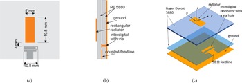
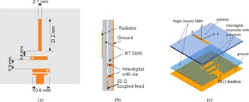
In this paper, we discuss filter antennas of different orders. The first design, Ant. I, is a filtering antenna based on second-order filters, while the second design, i.e. Ant. II, is based on third-order filter extraction. The geometric structure of Ant. I can be seen in Fig. 1(a), where it consists of two layers of substrates, a 7 mm × 19.5 mm rectangular radiator is on the first layer, and there is a feeding circuit that comprises an interdigital resonator coupled with a 50 ohm transmission line on the second layer. Figure 1(b) shows the design from the side view, and Fig. 1(c) is the exploded view of the two layers. Figure 2(a) shows the geometric structure of Ant. II, which consists of a 2.1 mm × 19.5 mm radiator on the top substrate that is proximity-coupled with the feeding network on the second substrate. Two interdigital resonators coupled with a 50 ohm transmission line are on the second substrate. A through hole with a diameter of 1.2 mm is set alternately at each end of the resonator's arm. There is 3.4 mm of space between the radiator and resonator and 5.9 mm of space between the two alternate resonators. The 50 ohm transmission line is coupled with a 0.7 mm gap. All structures are printed on two layers of 50 mm × 50 mm substrates. Figure 2(b) shows the antenna from the side view, which consists of a rectangular radiator on the top substrate and a feeding circuit at the bottom, while Fig. 2(c) shows the exploded view of the design. Both Ant. I and Ant. II use an interdigital resonator sized 2.4 mm × 10.8 mm and a through hole with a diameter of 1.2 mm.
(a) Geometric structure, (b) side view, and (c) perspective view of Ant. I.

(a) Geometric structure, (b) side view, and (c) perspective view of Ant. II.

The two designs are based on second- and third-order extraction filters, and both antennas are designed to operate at a frequency of 4.65 GHz and an operating bandwidth of 300 MHz or 6.45%. Following [Reference Matthaei, Young and Jones19], all lowpass filter parameters with a ripple of 0.2 dB are presented in Table 1. Furthermore, using (1) and (2) outlined in [Reference Hong and Lancaster20], the coupling parameters, radiation quality (Qrad), and external quality (Qext) can be calculated where FBW is the fractional bandwidth, the results of which are shown in Table 1.


Parameter filter extraction for second- and third-order filters

Next, we extract the radiator and resonator using (3) and (4), and CST simulation tools where fc is the center frequency, and △f is f 2–f 1. The structure extraction is conducted to obtain the resonant frequency and Qrad each for Ant. I and Ant. II. The radiator extraction also proves that to obtain a 4.65 GHz resonance, we can use different-sized rectangular radiators, as in Ant. I and Ant. II. The length (Lp) and width (Wp) of the Ant. I radiator, shown in Fig. 3(a), are 19.96 and 8.25 mm, respectively, to generate a 4.65 GHz operational frequency and Qrad of 13.06. A Qrad of 19.02 and operational frequency of 4.65 GHz can be obtained when the Lp and Wp of the Ant. II radiator are 21.2 and 2.8 mm, as shown in Fig. 3(b). Figure 4(a) shows the relation between Wp and Qrad at an operating frequency of 4.65 GHz; to obtain higher Qrad values, Wp should be reduced. The resonator's resonant frequency of 4.65 GHz is extracted by simulating the structure, as shown in Fig. 4(b).


The Qrad simulation extraction structure under different Wp values of (a) Ant. I and (b) Ant. II (all unit dimensions in mm).

(a) The Qrad values of Ant. I (red arrow) and Ant. II (blue arrow), (b) the interdigital resonator's resonance at different lengths (Pk) with a thickness of 2.4 mm.

The parametric study shows that the interdigital resonates at 4.65 GHz with a length (Pk) of 10.8 mm. The shorter the Pk the higher is the frequency resonance. For Ant. II, based on third-order filter extraction, it is necessary to ensure coupling between two resonators. A coupling value of 0.0542 is obtained using the two-port extraction curve from [Reference Cahyasiwi, Zulkifli and Rahardjo3] when the distance between the two resonators (Gap 1) is approximately 5.1 mm, as shown in Fig. 5(a). The coupling between the resonator and radiator is depicted in Fig. 5(b), with Qrad values of 13 and 19 for Ant. I and Ant. II, respectively. This shows that the distance between the resonator and radiator (CB) to obtain the associated coupling values (0.0702 and 0.0542) is around 3.87 mm for Ant. I and 3.65 mm for Ant. II. Finally, the initial dimensions of the two designs are achieved from these extractions.
(a) Coupling structure between two resonators for Ant. II and (b) the coupling between the radiator and resonator of Ant. I (Qrad = 19) and Ant. II (Q rad = 13) under different CB values.

Results and discussion
From the S 11 response of Ant. I in the initial design of Fig. 6(a), it is evident that the red curve does not convey the character of a second-order filter due to its single minimum value, and neither the bandwidth nor the center frequency parameters meet the desired values. Moreover, the design optimization result on the black curve shows the S 11 response, which is identical to a second-order filter response with two minimum values. As required, the center frequency occurs at 4.65 GHz, with an S 11 of −12.1 and −10 dB bandwidth impedance in the 4.48–4.8 GHz range. Figure 6(b) shows the initial design of Ant. II, where the S 11 response has three minimal values. However, the −10 dB bandwidth impedance is yet to be obtained. After optimization, as shown via the black curve, the −10 dB bandwidth impedance for a frequency range of 4.482–4.798 GHz is achieved with a center frequency of 4.65 GHz and a minimum S 11 value of −34 dB.
(a) The initial and optimized designs of second-order and (b) third-order interdigital filtering antennas.

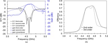
Figure 7(a) compares the S 11 values and gain responses of the two designs with conventional antennas without an integrated filter. Ant. I with an S 11 response as a second-order filter has a maximum gain of 5.89 dBi at 4.75 GHz, and the gain hovers around 5 dBi up to a frequency of 4.825 GHz, still high outside the operating bandwidth. Meanwhile, Ant. II has a maximum gain of 5.92 at 4.75 GHz and drops sharply to 1 dBi at 4.85 GHz. This shows that Ant. II blocks power beyond its operating bandwidth (4.5–4.8 GHz range) better than Ant. I. However, the selectivity of Ant. I is better than the conventional antenna because a traditional antenna's gain response decreases with a slope, so it does not resemble the response of a bandpass filter. In addition, the proposed designs have a wider bandwidth (300 MHz) than a conventional antenna (214 MHz). A comparison of both filtering antennas' efficiencies is shown in Fig. 7(b), where Ant. II has more ripple and a sharper curve than Ant. I. The maximum efficiencies of Ant. I and Ant. II are 0.78 and 0.75, respectively. The decreased efficiency from Ant. I and Ant. II can be attributed to the radiator size of Ant. II that is narrower than Ant. I.
(a) The optimized S 11 and gain simulation comparison of the second- and third-order and (b) the efficiency of the second- and third-order interdigital filtering antennas.

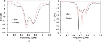
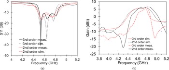
Both designs were fabricated and measured in an anechoic chamber for validation purposes. The fabricated filtering antennas are shown in Fig. 8, which depicts that Ant. I's radiator has a broader size compared to that of Ant. II. Using a ZNB 40 vector network analyzer, S 11 and the gain response were measured. Figure 9(a) compares the S 11 values obtained from the simulation and measurement results for Ant. I, from which it is evident that Ant. I has a −10 dB bandwidth impedance for a range of 4.501–4.847 GHz, which is 9% wider (and shifted to a higher frequency) compared to the simulation results. Figure 9(b) compares the S 11 values obtained from Ant. II's simulation and measurement results, from which it is evident that the measurement results shift to a higher frequency and have a 10% wider bandwidth for a range of 4.506–4.839 GHz compared to the simulation results. Figure 10(a) shows the Ant. I's gain measurement results, which slightly shifted to the upper frequency compared to the simulation results. With a maximum value of 6.48 dBi at 4.8 GHz, the measurement result is 0.6 dB higher than the simulation. Figure 10(b) shows that Ant. II's maximum gain is 6.37 dBi at 4.8 GHz, which decreases sharply to −15 dBi at 4.89 GHz, which indicates a gain blocking of 21 dB in both the lower and upper frequencies. Similar to the S 11 response, the gain response of both antennas also shifts toward higher frequencies. The discrepancy between the simulation and measurement results can be attributed to the two-layer design. In particular, a tiny air gap may exist between the layers, which explains the shift in operational frequency; otherwise, the shift may be due to substrate permittivity tolerance and fabrication errors. The S 11 simulation and measurement results of Ant. I in Fig. 11(a) show that with two minimal values, the parameter is characterized as a second-order filter, while Ant. II has three minimum values that correspond to the third-order filter response. The Ant. I and Ant. II selectivity comparison in Fig. 11(b) shows that Ant. II has a sharper bandpass filter response than Ant. I in the same operational bandwidth.
Fabrication (a) assembled (b) radiator on the first layer (c) filtering circuit of Ant. I, (d) assembled (e) radiator on the first layer (f) filtering circuit of Ant. II.

The S 11 measurement and simulation results comparison of (a) the second- and (b) third-order filtering antennas.

(a) Ant. I's gain comparison of simulation and measurement results, (b) Ant. II's gain comparison of simulation and measurement results.

(a) S 11 measurement and simulation results comparison of the second- and third-order filtering antennas and (b) gain measurement and simulation results comparison of the second- and third-order filtering antennas.

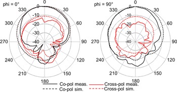
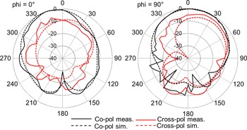
Figure 12 shows the normalized simulation and measurement radiation pattern of Ant. I at 4.65 GHz. The antenna has a unidirectional pattern at ϕ = 0° and ϕ = 90°, with main lobe directions both at θ = 0°, and the cross-polarization discriminant at ϕ = 0° is around 12 dB in the broadside. The normalized simulation and measurement radiation pattern of Ant. II are shown in Fig. 13, where the filtering antenna shows a broadside radiation pattern with a cross-polarization discriminant around 10 dB. The shift between the simulation and measurement results for Ant. I and Ant II is due to the fabrication error.
Ant. I's radiation pattern at 4.65 GHz.

Ant. II's radiation pattern at 4.65 GHz.

Table 2 provides a comparison of our designs and the previous filtering antennas, and it shows that even if the reference [Reference Mansour, Nugoolcharoenlap, Lancaster and Akkaraekthalin17] has the highest slope, it lacks the measurement validation. Reference [Reference Lin, Chiou and Chen18] also has better selectivity than the proposed designs; however, it used a higher order and caused a very low gain value due to the higher loss in the transmission line.
Comparison of the proposed filtering antennas with previous studies

a The sharpest slope is calculated as GmaxdB–20 dB/fmax–f 20 dB GHz, where Gmax is the maximum gain within the bandwidth, and fmax and f 20 are, respectively, the frequency points regarding to the decrease from the maximum realized gain by 20 dB [Reference Hu, Tang, Member, Li and Ziolkowski21].
Conclusion
In this paper, second- and third-order interdigital filtering antennas were designed, both of which have the same bandwidth and ripple, however the former has a wider rectangular radiator and lower Qrad values compared to the latter. The simulation results showed that the third-order interdigital filtering antenna has improve the selectivity of the second-order from 66 to 118 dB/GHz, with a relatively flat gain over the operational bandwidth. Both antennas were fabricated and measured. The simulation and measurement results are consistent.
Acknowledgement
This work was partly supported by Hibah Internal UHAMKA under Contract No. 786/F.03.07/2022. The authors would like to thank the Telecommunication Laboratory of Electrical Engineering Department – Faculty of Engineering Universitas Indonesia for providing the measurement laboratory and CST software.
 Dwi Astuti Cahyasiwi received her Bachelor, Magister, and Doctoral degrees in Electrical Engineering from the Universitas Indonesia in 1997, 2009, and 2022, respectively. She received Excellent Scholarship for Indonesia's Lecture (Beasiswa Unggulan Dosen Indonesia/BUDI-LPDP) for her Doctoral degree. She is a member of IEEE Antenna and Propagation Society (AP-S) since 2021 and a reviewer of IEEE Access since 2020. Cahyasiwi was a recipient of the Best Student Paper Award at the 2019 IEEE Conference on Antenna Measurement and Applications (CAMA). Her research interests are integration design of antenna and filter, multiple-input multiple-output (MIMO), dual-polarized antenna systems, metasurface, polarization converter, and microwave circuits.
 Emilia Roza received the Bachelor and Magister degrees in Electrical Engineering from the Universitas of Mercu Buana Indonesia in 1998 and 2015. Her research interests are antenna microstrip and filter.
 Mohammad Mujirudin received the Bachelor degree in Electrical Engineering from the Universitas Hasanuddin in 1996, and Magister in Electric Engineering from Universitas Indonesia in 2003. He received Scholarship for Indonesia's Lecture (Beasiswa BPPS). His research interests are antenna, microstrip filter, and robotics control.
 Nusriyati Mahmudah Nashuha received her Bachelor degree in Electrical Engineering from the Telkom University in 2011, and Magister in Electric Engineering from Universitas Indonesia in 2019. Her research interests are wireless communication, coding in multiple access, and antenna propagation.
 Fitri Yuli Zulkifli received her Bachelor and Ph.D. degrees in Electrical Engineering from Universitas Indonesia (UI) in 1997 and 2009, while M.Sc. degree from Karlsruhe Institute of Technology, Germany in 2002. Her research interests are antenna, propagation, microwave, and in the field of telecommunication. She joined the Antenna Propagation and Microwave Research Group (AMRG) UI since 1997 and has become lecturer in Electrical Engineering Department UI since 1998. Prof. Yuli has published more than 200 papers in journals/conference proceedings and received more than 40 research grants. She now leads “Laboratory Prof. Fitri Yuli Zulkifli” and also the head of professional engineering study program in UI. From 2011 to 2012 she became the joint chapter chair of MTT/AP Indonesia. In 2017–2018, she was the IEEE Indonesia Section Chair and from 2019 to 2022, she has been serving as a committee member for R10 Conference and Technical Seminar and Conference Quality Management.
 Eko Tjipto Rahardjo received B. Eng. degree from Universitas Indonesia, Indonesia, in 1981, the M.S. degree from the University of Hawaii, USA, in 1987, and the Ph.D. degree from Saitama University, Japan, in 1996, all in Electrical Engineering. He has been the Director of Antenna Propagation and Microwave Research Group (AMRG), Universitas Indonesia. His research interests include antenna engineering, wave propagation, microwave circuits and communication systems, and telecommunication system regulations. He has published and presented more than 200 research articles both in national and international journals and symposiums. Prof. Rahardjo is a member of the IEEE Antenna and Propagation Society (AP-S) and the IEEE Microwave Theory and Technique Society (MTTS) and has been actively participating in the National and International Committee as the International Advisory Board, Steering Committee, or General Chair in the International Symposium on Antenna and Propagation (ISAP), Asia Pacific Microwaves Conference (APMC), and IEEE Conference on Antenna Measurement and Applications (CAMA).