



Introduction
A conventional microstrip antenna generates a narrow resonant frequency band with low gain, and most of the time, the generated resonant band does not occupy the desired application band [Reference Wang, Cheng, Luo, Chen and Wu1–Reference Sun, Cai, Yang, Wu, Cheng, Luo, Chen and Li5]. Therefore, the resonant band needs to be shifted so that it can cover the desired application band along with enhanced gain and bandwidth. There are many techniques available in the open literature that can be used to shift the resonant band with increased gain and bandwidth of the antenna. For example, variation of the patch size [Reference Ekşım and Cumurcu6, Reference Mishra, Kuchhal and Kumar7], use of different substrate materials [Reference Jain and Gupta8, Reference Mane, Patil and Dhanawade9], slotting or slitting radiating patch [Reference Jin and Zhang10, Reference Shaw, Mandal and Gangopadhyay11], addition of stub in the patch [Reference Shaw, Mandal and Gangopadhyay12], shorting patch with ground using metallic posts and pins [Reference Zhuang and Shafai13, Reference Sheta and Mahmoud14], defected ground structure [Reference Ripin, Yusoff, Sulaiman, Rashid and Hussin15, Reference Sarkar, Ghosh, Singh, Chattopadhyay and Sim16], and metamaterial [Reference Saghanezhad and Atlasbaf17, Reference Majedi and Attari18]. In [Reference Ekşım and Cumurcu6], a microstrip antenna was designed for high and very high frequencies. A different approach was used: first, a dipole antenna was considered for a certain frequency at which the microstrip antenna operates, and then the antenna length was calculated for the same resonance frequency. The study in [Reference Mishra, Kuchhal and Kumar7] investigates how changes in substrate thickness and patch width affect the performance of a rectangular patch antenna. By varying one parameter while keeping the other constant, the impact on the antenna’s resonant frequency, bandwidth, and gain was analyzed. In [Reference Jain and Gupta8] and [Reference Mane, Patil and Dhanawade9], studies on the effect of different dielectric substrates used in microstrip patch antennas to enhance the overall efficiency were conducted. References [Reference Jin and Zhang10] and [Reference Shaw, Mandal and Gangopadhyay11] propose a microstrip antenna design featuring two rectangular patches of different sizes, connected by a microstrip line and fed coaxially. The bandwidth enhancement of the antenna is achieved by introducing long slots at strategic locations on each patch, enabling dual-mode resonance and improved impedance matching across multiple frequency bands. A low-profile circular patch antenna design incorporating two optimized slits and a stub had been presented in [Reference Shaw, Mandal and Gangopadhyay12]. The stub is attached to the circular radiating patch to shift and fine-tune the antenna’s two resonant frequency bands. In [Reference Zhuang and Shafai13], a study was done to investigate the shifting of the resonant frequency of microstrip disk antennas due to a shorting post. Also, it had been investigated the effects of shorting-post size and location on the resonant modes. In [Reference Sheta and Mahmoud14], a resonant frequency tunable patch antenna had been designed using some posts close to the patch edge. The posts are short-circuited to the ground via a set of PIN diodes. The published designs of the microstrip patch antennas have some merits and demerits. The recessed ground structure (RG) is also a technique for shifting the resonant band with enhancement of the gain and the bandwidth of the microstrip antenna [Reference Shaw19]. A literature survey shows that very few works have been reported so far on microstrip patch antennas with RGs. Further, as per the author’s knowledge, there is no work to predict the primary resonant frequency of the microstrip patch antenna with recessed ground size. Therefore, it is chosen over others to represent the proposed work.
In this work, a low-profile elliptical microstrip antenna was designed using the recessed ground for (2.5–2.69 GHz) WiMAX application band. A theoretical analysis of the antenna with the recessed ground has been done using a 2-D capacitance model to predict the reduction in effective dielectric constant with variation of dimensions of the recessed ground and amount of shifting of the resonant frequency. To show the validity of the mathematical theory, the resonant frequency of the antenna with RG is compared with experimental data for three different recessed ground sizes.
The remainder of this manuscript is divided as follows. Section II presents the design of the proposed antenna. Section III illustrates the effects of recessed ground parameters on the performance of the antenna with theoretical analysis using a 2-D capacitance model, and Section IV details the fabrication and measurement results.
Antenna design
The projected antenna is shown in Fig. 1, which consists of an elliptical-shaped radiating patch with a semi-major axis of 17.5 mm and a semi-minor axis of 8.75 mm. The overall size of the proposed antenna is 48 × 30 × 4 mm3 in which a thin copper sheet has been used to make a radiating patch, and a rectangular-shaped 0.8 mm thick copper sheet has been used to make the ground plane. The rectangular-shaped substrate of 3.2 mm height between the patch and ground has been made using FR4 material whose relative permittivity (εr) is 4.4 and loss tangent (tan δ) is 0.02. Three rectangular-shaped portions of dimension 20 × 10 × 0.8 mm3, 29 × 10 × 0.8 mm3, and 35 × 10 × 0.8 mm3 have been cut out from the ground for the realization of the RG. The position of the substrate cut-out is shown in Fig. 1. A 50 Ω coaxial probe SMA connector with a 0.63 mm inner radius and 1.45 mm outer radius has been attached to the antenna at a distance of 11.3 mm from the upper edge and 17 mm from the right edge of the antenna, in order to energize it.
(a) Design of the proposed antenna. (b) Top view of the fabricated antenna. (c) Bottom view of the fabricated antenna. (d) Fabricated recessed ground with a cut out of (20 × 10) mm2 dimension. (e) Fabricated recessed ground with a cut out of (29 × 10) mm2 dimension. (f) Fabricated recessed ground with a cut out of (35 × 10) mm2 dimension.

Antenna design procedure with parametric study
For the design of the projected antenna, first, an elliptical-shaped radiating patch has been selected, so that a low-profile antenna can be designed. After that, a theoretical calculation has been done with various semi-major axis and semi-minor axis lengths of the radiating patch and mathematical equations (1)–(6) [Reference Murugan, Rohini, Muthumari and Padma Priya20–Reference Kumprasert22] to find the resonant frequency of the antenna around (2.5–2.69 GHz) WiMAX application band.
 \begin{equation}{f_r} = \frac{{c\sqrt q }}{{\pi e{a_{eff}}\sqrt {{\varepsilon _r}} }}\end{equation}
 \begin{equation}e = \sqrt {1 - {{(b/a)}^2}} \end{equation}
 \begin{align}a_{eff} &= a\Big[1 + \frac{2h}{\varepsilon_{r}\pi a}\left\{In(\frac{a}{2h}) + (1.41{\varepsilon _r} + 1.77)\right.\nonumber\\
&\quad\left.+ \frac{h}{a}(0.268{\varepsilon _r} + 1.65) \right\}\Big]^{1/2}\end{align}
 \begin{align}b_{eff} &= b\Big[1 + \frac{2h}{\varepsilon_{r}\pi b}\left\{In(\frac{b}{2h}) + (1.41\varepsilon_{r} + 1.77) \right. \nonumber\\
&\quad\left. + \frac{h}{b}(0.268{\varepsilon_{r} + 1.65)} \right\}\Big]^{1/2}\end{align}
In the mathematical equations (1) to (4), fr represent the resonant frequency of the antenna, a and b represent the semi major axis and the semi minor axis of the elliptical patch, a eff and b eff represent the effective semi major axis and the effective semi minor axis of the elliptical patch, c represent speed of light in free space (c = 3 × 1010 cm/sec), e represent eccentricity of the elliptical patch, and q represent approximated Mathieu function of the given mode.
The principle mode of the elliptical patch antenna is TM11, which is based on the q-value function. Then the q value for TM11 mode is
 \begin{align}{\text{q}_{11}} &= 0.847{e^2} - 0.0013{e^3} \nonumber\\
&\quad + 0.0379{e^4},\ \text{for}\ \text{the}\ \unicode{x2018}e
\unicode{x2019}\ \text{values}\ \text{between}\ 0\ \text{and}\ 0 {.4}\end{align}
 \begin{align}{\text{q}_{11}} &= - 0.0064e + 0.8838{e^2} - 0.0696{e^3} \nonumber\\
&\quad+ 0.082{e^4},\ \text{for}\ {\text{the}\ \unicode{x2018}e\unicode{x2019}\ \text{value}\ \text{between}\ 0}{.4\ \text{and}\ 1}\end{align}
After various theoretical calculations, the semi-major axis of 17.5 mm and semi-minor axis of 8.75 mm of the radiating patch provided a primary resonant frequency (TM11 mode) of 2.36 GHz close to the needed result. For the above semi-major and minor axes, the “e” is 0.866, and q11 is 0.658.
Having a theoretical resonant frequency of 2.36 GHz, an elliptical microstrip patch antenna has been designed using simulator software HFSS. During the design process, first, the ground plane has been designed with the dimensions (48 × 30 × 0.8) mm3, then the same-sized substrate has been made above the ground plane with a height of 3.2 mm. After that, an elliptical-shaped radiating patch has been designed above the substrate with a semi-major axis of 17.5 mm and a semi-minor axis of 8.75 mm. Next, a coaxial probe with a 0.63 mm inner radius and 1.45 mm outer radius has been designed and attached to the antenna to provide the signal. Finally, a radiation box has been made around the open space of the antenna. After completion of the design process, the boundary conditions have been applied to the antenna structure, such as the perfect electric conductor to the patch and ground, Wave Port to the coaxial probe, and Radiation Boundary to open space around the antenna. The Radiation Boundary has been placed λ/4 (quarter-wavelength) away from the antenna structure to avoid near-field effects and reflections.
With the above-mentioned specifications and at the arbitrary probe position, the designed antenna is simulated, and the principle resonant frequency is found to be 2.35 GHz, almost the same as the theoretical resonant frequency with a poor reflection coefficient (S 11). The reflection coefficient (S 11) is poor because of the antenna impedance mismatch with the probe due to the arbitrary probe position. Therefore, the probe position has been optimized by shifting the probe 1 mm horizontally from the left end to the right end along the major axis of the patch and subsequently analyzing the simulated results. After that, the probe is placed 1 mm vertically along the minor axis, and again the probe is shifted 1 mm horizontally from the left end to the right end along the major axis, and the simulated results are analyzed. In this way, all the patch areas have been investigated with the probe, and finally, the probe position 11.3 mm from the upper edge and 17 mm from the right edge of the antenna has been found optimum. At the optimum probe position, the resonant frequency band is (2.28–2.4 GHz) as shown in Fig. 2 (b). The initial design of the antenna with reflection coefficient (S 11) and input impedance (Z 11) graphs is displayed in Fig. 2 (a)–(c). The initial design of the projected antenna shown in Fig. 2 (a) does not fulfill the desired result. Therefore, it has been modified using the techniques and processes mentioned below.
(a) Initial design of the proposed antenna with optimum probe position. (b) S11 and (c) Z11 of the initial antenna at the above-mentioned probe position.

Effect of RG
The resonant band generated by the conventional antenna shown in Fig. 2 (a) needs shifting so that it can occupy the desired application band with improvement of gain and bandwidth. For this purpose, an RG has been used. Initially, a rectangular-shaped portion of the ground of the dimensions (20 × 10 × 0.8) mm3 has been cut out for the implementation of the recessed ground. Due to the cut-out in the ground, the vacant portion of it is filled with air.
Therefore, the overall relative permittivity of the substrate is reduced, which causes a shift of the resonant frequency toward a higher frequency range from 2.35 to 2.37 GHz with resonant frequency band (2.29–2.45 GHz). Apart from the shift of the resonant frequency, the bandwidth and gain increased from 120 to 160 MHz and from −1.35 to −0.6 dB, respectively. The presence of recessed ground below the substrate causes an increase in its electromagnetic volume and therefore increases the bandwidth of the antenna [Reference Eswarappa23]. The recessed ground also causes an increase in fringing fields and reduced losses in the antenna, due to which gain and efficiency improved. The position of the recessed ground has been optimized by changing the positions and subsequent analysis of the simulated results.
Analysis of the RG using a 2-D capacitance model
A 2-D capacitance model [Reference Jaiswal, Abegaonkar and Koul24] along with mathematical formulas has been presented here in order to find the variation of dielectric constant and amount of shift of principle resonant frequency with different sizes of the recessed ground.
The electric fields at the edge of the elliptical patch undergo fringing; this is illustrated in Fig. 3 (a), (b). Due to the fringing effects, electrically, the patch of the microstrip antenna looks larger than its original physical size. Therefore, the effective semi-major (a eff) and minor axis (b eff) become 19.57 and 10.7 mm. The calculated effective dielectric constant (ɛ eff) below the fringing region is 3.74 using equation (7) for the antenna shown in Fig. 3 (a), (b).
 \begin{equation}{\varepsilon _{eff}} = \frac{{{\varepsilon _r} + 1}}{2} + \frac{{{\varepsilon _r} - 1}}{2}{\left\{ {1 + \frac{{10h}}{{2b}}} \right\}^{ - 1/2}}\end{equation}
(a) and (b) Antenna design with recessed ground. (c) S11 and (d) Z11 of the above antenna.

In the mathematical equation (7), ɛ eff, εr, and h represent the effective relative permittivity, the relative permittivity, and the height of the FR4 substrate, b represents the semi-minor axis of the elliptical patch.
Figure 3 (a) shows the antenna design with recessed ground having length, breadth, and height of 20, 10, and 0.8 mm. Figure 3 (b) represents a quasi-static capacitance model based on parallel capacitances (Cf and Cpwrg) and series capacitances (Cp and Crg) between the patch and recessed ground for the areas (Af, Apwrg, Ap, and Arg).
Af = fringing area of the patch
Apwrg = area of the patch outside of the recessed ground area
Ap = area of the patch above the recessed ground area
Arg = area of the recessed ground
Af = 176.86 mm2
Ap = Arg = 200 mm2
Apwrg = 481.25 − 200 = 281.25 mm2
Total capacitance (Ct) is a combination of fringing region capacitance (Cf), non-fringing region capacitance (Cpwrg), and mixed air-substrate region capacitances (Cp and Crg) and is calculated as
 \begin{equation*}{{\text{C}}_{\text{t}}}{\text{ = }}{{\text{C}}_{\text{f}}}{\text{ + }}{{\text{C}}_{{\text{pwrg}}}}{\text{ + }}\left( {{{\text{C}}_{\text{p}}}{\text{\& }}{{\text{C}}_{{\text{rg}}}}} \right)\end{equation*}
It is known that
 \begin{equation}Capaci\tan ce(C) = \frac{{{\varepsilon _{eff}} \times Area}}{{3.2(Substrate - height)}}\end{equation}
Using equation (8), the calculated capacitance values of Af, Apwrg, Ap, and Arg are 2.07 pF, 3.87 pF, 2.75 pF, and 2.50 pF.
Since the capacitances (Cp and Crg) are in series, the equivalent capacitances
 \begin{equation*}{C_{eq}} = \frac{{275 \times 250}}{{275 + 250}} = 1.31{\text{ pF}}\end{equation*}
Hence, the total capacitance Ct = Cf + Cpwrg + Ceq = 7.24 pF. Placing this value in equation (8), the calculated value for the effective permittivity is 3.52. By including it in equation (1), the resonant frequency of f r = 2.43 GHz has been found.
The calculated principle resonant frequency using the 2-D capacitance model is 2.43 GHz and simulated and measured principle resonant frequency are 2.37 and 2.39 GHz. The simulated reflection coefficient (S 11) and input impedance (Z 11) graphs of the above-modified antenna are displayed in Fig. 3 (c), (d). From Fig. 3 (c), (d), it can be observed that the above-recessed ground needs further modification so that the resonant band shifts and occupies the desired application band.
Analysis of the RG with changes in the length
In order to improve the performance of the antenna, the recessed ground has been modified by increasing its length from 20 to 29 mm, keeping the breadth same. After modification, the resonant frequency shifted from 2.37 to 2.49 GHz with a resonant frequency band (2.4–2.58 GHz). Also, increased bandwidth and gain are 160–180 MHz and −0.6 to 0.05 dB.
Figure 4 (a) shows the antenna design with recessed ground having length, breadth, and height of 29, 10, and 0.8 mm. Figure 4 (b) represents a quasi-static capacitance model based on parallel capacitances  $\left( {{{\text{C}}_{\text{f}}}{\text{\& }}{{\text{C}}_{{\text{pwrg}}}}} \right)$ and series capacitances
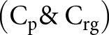 $\left( {{{\text{C}}_{\text{p}}}{\text{\& }}{{\text{C}}_{{\text{rg}}}}} \right)$ between the patch and recessed ground for the areas
 $\left( {{{\text{A}}_{\text{f}}}{\text{, }}{{\text{A}}_{{\text{pwrg}}}}{\text{, }}{{\text{A}}_{\text{p}}}{\text{\& }}{{\text{A}}_{{\text{rg}}}}} \right)$.
 \begin{equation*}{{\text{A}}_{\text{f}}}{\text{ = 176}}{\text{.86 m}}{{\text{m}}^{\text{2}}}\end{equation*}
 \begin{equation*}{{\text{A}}_{\text{p}}}{\text{ = }}{{\text{A}}_{{\text{rg}}}}{\text{ = 290 m}}{{\text{m}}^{\text{2}}}\end{equation*}
 \begin{equation*}{{\text{A}}_{{\text{pwrg}}}}{\text{ = 481}}{\text{.25 - 290 = 191}}{\text{.25 m}}{{\text{m}}^{\text{2}}}\end{equation*}
(a) and (b) Antenna design with modified recessed ground. (c) S11 and (d) Z11 of the modified recessed ground antenna.

Total capacitance (Ct) is a combination of fringing region capacitance (Cf), non-fringing region capacitance (Cpwrg), and mixed air-substrate region capacitances (Cp&Crg) and is calculated as
 \begin{equation*}{{\text{C}}_{\text{t}}}{\text{ = }}{{\text{C}}_{\text{f}}}{\text{ + }}{{\text{C}}_{{\text{pwrg}}}}{\text{ + }}\left( {{{\text{C}}_{{\text{rp}}}}{\text{\& }}{{\text{C}}_{{\text{rg}}}}} \right)\end{equation*}
Using equation (8), the calculated capacitance values of Af, Apwrg, Ap, and Arg are 2.07 pF, 2.63 pF, 3.99 pF, and 3.63 pF.
Since the capacitances (Cp and Crg) area are in series, the equivalent capacitances
 \begin{equation*}{C_{eq}} = \frac{{398.75 \times 362.5}}{{398.75 + 362.5}} = 1.90{\text{ pF}}\end{equation*}
Hence, the total capacitance Ct = Cf + Cpwrg + Ceq = 6.60 pF. Placing this value in equation (8), the calculated value for the effective permittivity is 3.2. By including it in equation (1), the resonant frequency of f r = 2.55 GHz has been found.
The calculated principle resonant frequency using the 2-D capacitance model is 2.55 GHz and simulated and measured principle resonant frequency is 2.49 and 2.5 GHz. The position of the recessed ground has been optimized by changing the positions and subsequent analysis of the results. The simulated reflection coefficient (S 11) and input impedance (Z 11) graphs of the above-modified antenna are displayed in Fig. 4 (c), (d). From Fig. 4 (c), (d), it can be observed that the antenna with modified recessed ground generates a frequency band (2.4–2.58 GHz) which covers (2.4–2.48 GHz) ISM application band. Therefore, the antenna with the above recessed ground specification can be used for the ISM application band. However, in order to achieve the improved resonant band of the antenna that can cover the desired application band, the above-recessed ground needs further modification.
Analysis of the RG with further changes in the length
In order to further shift the resonant band for the desired application of the antenna, the length of the recessed ground has been increased from 29 to 35 mm, keeping breadth constant, and analyzed the subsequent results. With the increase in the length, the area of the recessed ground also increased, causing the shift of the resonant band. At the 35 mm length of the recessed ground, it has been observed that the resonant band of the antenna occupies the desired application band as shown in Fig. 5 (c), (d).
(a) and (b) Antenna design with further modified recessed ground. (c) S11 and (d) Z11 of the above antenna.

Figure 5 (a) shows the antenna design with recessed ground having length, breadth, and height of 35, 10, and 0.8 mm. Figure 5 (b) represents a quasi-static capacitance model based on parallel capacitances  $\left( {{{\text{C}}_{\text{f}}}{\text{\& }}{{\text{C}}_{{\text{pwrg}}}}} \right)$ and series capacitances
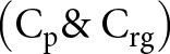 $\left( {{{\text{C}}_{\text{p}}}{\text{\& }}{{\text{C}}_{{\text{rg}}}}} \right)$ and
 $\left( {{{\text{C}}_{{\text{cf}}}}{\text{\& }}{{\text{C}}_{{\text{crg}}}}} \right)$ between the patch and recessed ground for the areas
 $\left( {{{\text{A}}_{\text{f}}}{\text{, }}{{\text{A}}_{{\text{pwrg}}}}{\text{, }}{{\text{A}}_{\text{p}}}{\text{, }}{{\text{A}}_{{\text{rg}}}}{\text{, }}{{\text{A}}_{{\text{cf}}}}{\text{\& }}{{\text{A}}_{{\text{crg}}}}} \right)$.
Acf = corner fringing area of the patch
Acrg = corner area of the recessed ground below the corner fringing area of the patch
Total capacitance (Ct) is a combination of fringing region capacitance (Cf), non-fringing region capacitance (Cpwrg), and mixed air-substrate region capacitances (Cp and Crg) and (Ccf and Ccrg), and is calculated as
 \begin{equation*}{{\text{C}}_{\text{t}}}{\text{ = }}{{\text{C}}_{\text{f}}}{\text{ + }}{{\text{C}}_{{\text{pwrg}}}}{\text{ + }}\left( {{{\text{C}}_{{\text{rp}}}}{\text{\& }}{{\text{C}}_{{\text{rg}}}}} \right){\text{ + }}\left( {{{\text{C}}_{{\text{cf}}}}{\text{\& }}{{\text{C}}_{{\text{crg}}}}} \right)\end{equation*}
The area of the patch region (a, b, and c) shown in Fig. 5 (a) has been calculated using the equations below:
 \begin{equation}\frac{{{x^2}}}{{{a^2}}} + \frac{{{y^2}}}{{{b^2}}} = 1\end{equation}
Or, 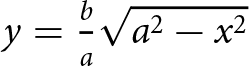 $y = \frac{b}{a}\sqrt {{a^2} - {x^2}} $
Area of the patch region (a, b, and c) 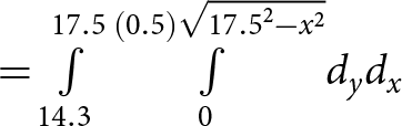 $ = \int\limits_{14.3}^{17.5} {\int\limits_0^{(0.5)\sqrt {{{17.5}^2} - {x^2}} } {{d_y}{d_x}} } $
 $ = \int\limits_{14.3}^{17.5} {[y]_0^{(0.5)\sqrt {{{17.5}^2} - {x^2}} } {{d_x}} } $
 \begin{equation*} = (0.5)\int\limits_{14.3}^{17.5} {\sqrt {{{17.5}^2} - {x^2}} {d_x}} = 10.95{\text{ }}m{m^2}\end{equation*}
Area of the patch region (a, b, and c) + Corner fringing area of the patch (Acf) = 5 × 3.2 = 16 mm2
Corner fringing area of the patch (Acf) = 16 − 10.95 = 5.05 mm2
Four corners fringing area of the patch (4 × Acf) = 5.05 × 4 = 20.2 mm2
Fringing area without corner fringing area of the patch [Af − (4 × Acf)] = 176.86 − 20.2 = 156.66 mm2
 \begin{equation*}{{\text{A}}_{{\text{pwrg}}}}{\text{ = 481}}{\text{.25 - 329}}{\text{.8 = 151}}{\text{.45 m}}{{\text{m}}^{\text{2}}}\end{equation*}
 \begin{equation*}{{\text{A}}_{\text{p}}}{\text{ = 35X10 = 350 - 20}}{\text{.2 = 329}}{\text{.8 m}}{{\text{m}}^{\text{2}}}\end{equation*}
Area of the recessed ground without corner area of it (Arg − Acf) = 35 × 10 = 350 − 20.2 = 329.8 mm2
Four corners recessed ground area (4 × Acrg) = 20.2 mm2
Capacitance of four corners fringing area of the patch  $\left( {4x{C_{cf}}} \right) = \frac{{3.74 \times 20.2}}{{3.2}} = 0.236{\text{ pF}}$
Using equation (8), the calculated capacitance values of Cf, Apwrg, Ap, and Crg are 1.83, 2.08, 4.53, and 4.12 pF.
Capacitance of four corners recessed ground area  $\left( {4x{C_{crg}}} \right)\,\;\frac{{1 \times 20.2}}{{0.8}} = 0.25{\text{ pF}}$
The capacitances (Cp and Crg) are in series; therefore, the equivalent capacitances
 \begin{equation*}{C_{eq1}} = \frac{{453.475 \times 412.25}}{{453.475 + 412.25}} = 2.16{\text{ pF}}\end{equation*}
The capacitances (Ccf and Ccrg) are in series; therefore, the equivalent capacitances
 \begin{equation*}{C_{eq2}} = \frac{{23.6 \times 25.25}}{{23.6 + 25.25}} = 0.12{\text{ pF}}\end{equation*}
Hence, the total capacitance  ${{\text{C}}_{\text{t}}}{\text{ = }}{{\text{C}}_{\text{f}}}{\text{ + }}{{\text{C}}_{{\text{pwrg}}}}{\text{ + }}{{\text{C}}_{{\text{eq1}}}}{\text{ + }}{{\text{C}}_{{\text{eq2}}}}$
 ${\text{ = 6}}{\text{.19 pF}}$
 \begin{equation*}619.48 = \frac{{{\varepsilon _{eff}} \times 658.11}}{{3.2}}\end{equation*}
ɛ eff = 3.01 and f r = 2.63 GHz (using equation 1)
Hence, the total capacitance  ${{\text{C}}_{\text{t}}}{\text{ = }}{{\text{C}}_{\text{f}}}{\text{ + }}{{\text{C}}_{{\text{pwrg}}}}{\text{ + }}{{\text{C}}_{{\text{eq1}}}}{\text{ + }}{{\text{C}}_{{\text{eq2}}}}$
 ${\text{ = 6}}{\text{.19 pF}}$. Placing this value in equation (8), the calculated value for the effective permittivity is 3.01. By including it in equation (1), the resonant frequency of f r = 2.63 GHz has been found.
After modification in the recessed ground, the resonant frequency shifted from 2.49 to 2.58 GHz with a resonant frequency band (2.49–2.69 GHz) and occupied the desired (2.5–2.69 GHz) WiMAX application band. Also, increased bandwidth and gain are 180 to 200 MHz and 0.05 to 0.5 dB. The calculated principle resonant frequency using the 2-D capacitance model is 2.63 GHz and simulated and measured principle resonant frequency is 2.58 and 2.59 GHz. The position of the ground cut-out has been optimized by changing the positions and subsequent observation of the simulated results.
The percentage error between measured and theoretically calculated principle resonant frequency using the capacitive model with different recessed ground sizes has been summarized in Table 1.
The percentage error between measured and theoretically calculated principle resonant frequency using the capacitive model with different recessed ground sizes.

A tabular representation of the variation of the simulated principle resonant frequency with various lengths of the recessed ground, keeping breadth 10 mm and height 0.8 mm has been given in Table 2 with a graph.
A tabular representation of the variation of the simulated principle resonant frequency with various lengths of the recessed ground, keeping the breadth 10 mm and height 0.8 mm.

Analysis of the RG with changes in the breadth
Like a variation of the length, an increase in the breadth of the recessed ground also increases its size causing a shift in the resonant band with the principle resonant frequency of the antenna. In order to observe the shift in principle resonant frequency with a change in breadth, the breadth has been increased from 10 to 12 mm keeping length and height constant, and analyzed the results. The simulated resonant frequency at 12 mm breadth is 2.38 GHz. Again, breadth has been increased to 14, 16, and 17.5 mm with constant length and height, and analyzed the results. The simulated resonant frequencies were 2.37, 2.36, and 2.36 GHz. A tabular representation of the variation of the principle resonant frequency with various breadth values of the recessed ground, keeping a length of 20 mm and a height of 0.8 mm has been given in Table 3.
A tabular representation of the variation of the principle resonant frequency with various breadth values of the recessed ground, keeping a length of 20 mm and a height of 0.8 mm.

Analysis of the RG with changes in the height
Like a variation of the length and breadth, an increase in the height of the recessed ground also increases its size causing a shift in the resonant band with the principle resonant frequency of the antenna. In order to observe the shift in principle resonant frequency with a change in height, the height has been increased from 0.2 to 0.4 mm keeping length and breadth constant, and analyzed the results. The simulated resonant frequency at 0.4 mm height is 2.1 GHz. Again, height has been increased to 0.6, 0.7, and 0.8 mm with constant length and breadth, and analyzed the results. The simulated resonant frequencies have been found 2.25, 2.31, and 2.37 GHz. A tabular representation of the variation of the principle resonant frequency with various height values of the recessed ground, keeping a length of 20 mm and a breadth of 10 mm has been given in Table 4.
A tabular representation of the variation of the principle resonant frequency with various height values of the recessed ground, keeping a length of 20 mm and a breadth of 10 mm.

Following the above process and capacitive model, the final design of the antenna has been made, and a prototype of it has been fabricated as displayed in Fig. 1 (b)–(d). The different parameters of the fabricated antenna have been measured using a Vector Network Analyzer benchtop (Model No. MS 46122B) and an anechoic chamber.
Results
The simulated and measured results for different parameters of the final designed antenna have been summarized in Table 5.
The simulated and measured results for different parameters of the final designed antenna.

Graphs of different parameters of the antenna with measured results are shown in Figs. 6–8.
From the above graphs shown in Figs. 6–8 it can be observed that the measured and simulated results closely match with a little shift in the measured results due to various factors, such as the actual dielectric constant of the substrate may differ from the manufacturer’s specifications and also, environmental (temperature and humidity) factors can affect the dielectric properties of the substrate, causes a small change in the resonance frequency, impedance matching and the attenuation of the signal. Imperfect conductor and the substrate surface losses, and the conductor’s ohmic loss cause changes in gain and efficiency. Poor soldering of connectors can introduce parasitic inductance and resistance, affecting the resonance frequency and impedance matching. Unintended radiation from feed lines and an imperfect anechoic chamber introduces unwanted reflections and causes a change in the measured pattern, which is not considered during the simulation.
Measured and simulated radiation efficiency.

Measured and simulated gain.

(a) Normalized radiation pattern in X-Z plane and (b) Y-Z plane at 2.58 GHz frequency.

The radiation characteristics of an antenna are a function of space coordinates, and it is often described in two planes (Phi = 0° and 90°) with theta (Ɵ) between 0° and 360°. Figure 8 (a), (b) shows the simulated and measured radiation pattern of the designed antenna with co-pol and cross-pol at 2.58 GHz frequency, and it can be seen that the proposed antenna has a broadside radiation pattern.
The advantages of the proposed antenna structure compared with the previous one
1. The proposed antenna structure is simple and low-profile with an elliptical patch and recessed ground. There are no major complex techniques used in the design which adds unnecessary complexity.
2. Variation in effective dielectric constant and shifting of the resonant band can be controlled by changing the dimension of the recessed ground. Therefore, the resonant band of the antenna can be easily shifted to the desired frequency band using different-sized recessed ground, which makes the proposed antenna design low profile, simple, and easy to fabricate.
3. Due to its simplicity, low cost, and ease of fabrication, the proposed antenna is very much suitable as per the requirement of the advanced communication technology and also fulfills low-cost commercial demand.
4. The reduction in effective dielectric constant with variation of dimensions of the recessed ground and amount of shifting of the resonant frequency can be easily predicted theoretically using a 2-D capacitance model.
Conclusion
In this article, a low-profile elliptical microstrip antenna has been designed with an RG. The introduction of rectangular-shaped recessed ground with a conventional antenna is investigated theoretically for the first time using a 2-D capacitance model to understand the effect of its dimensions on the dielectric constant and the amount of shifting of the resonant band. The designed antenna in the proposed work covers (2.5–2.69 GHz) WiMAX application band with satisfactory radiation pattern, gain, and radiation efficiency. Next, a complete design process has been described, including a theoretical calculation using mathematical equations with proper reason and justification at every step of the process. It is found that the theoretical calculation of the principle resonant frequency using the capacitance model for three different recessed ground sizes of the antenna shows close agreement with measured and simulated results. This theory can also be used with different shapes of radiating patches and recessed ground. The recessed ground technique is much simpler to design and has a lower fabrication cost.
Acknowledgments
Heartfelt thanks to Dr. Ardhendu Kundu of the IEDC lab at the Institute of Engineering & Management, Salt Lake, for helping in the fabrication of the prototype antenna as well as the measurement of its different parameters using VNA.
Data availability statement
The data that support the findings of this study will be available from the author upon reasonable request.
Conflict(s) of interest
“This research received no specific grant from any funding agency, commercial or not-for-profit sectors.” The author reports no conflict of interest. There are no known competing financial interests or personal relationships that could appear to have influenced the work reported in this paper.

Murari Shaw was born in 4 July 1980. He received his M.Tech. from Calcutta University in 2015 and Ph.D. in 2021 from University of Engineering and Management. His research interests include Microstrip patch antenna.
Author ORCID: M. Shaw, https://orcid.org/0000-0002-8405-8044.



