1. Introduction
Robots often perform constrained tasks that require high position and force control accuracy such as grinding, polishing, and assembly [Reference Roveda, Vicentini and Tosatti1]. How to give the reference position and attitude of the robot is very important for the trajectory and force control. In the structured environment, the geometry of the surface is often considered to be known and can be obtained from the CAD. In the unstructured environment, the geometry of the surface can be obtained by laser scanning [Reference Zhuang, Lin, Hu and Guo2], vision [Reference Huang, Lan and Li3], human teaching on the surface [Reference Lin4], etc. Using these methods, the reference trajectory can be given for robot trajectory planning.
Surface modeling: It is also important for the robot to learn surface constraints autonomously in the uncertain environment. Some scholars use the six-axis force sensor for online estimation of surface normal vectors and curvatures. In ref. [Reference Jiang, Xu and Xie5], the surface normal vector and curvature are estimated online based on the force information from the force sensor for the spherical tool. The contour tracking and force control on the bulb are realized by a 3-axis Cartesian robot. In ref. [Reference Yin, Hu and Xia6], the force at the contact point is derived precisely considering the Coulomb friction model. In refs. [Reference Yin, Xu, Jiang and Wang7, Reference Yip and Camarillo8], the force sensor information is used to predict the robot trajectory on the unknown surface. The Coulomb friction model is also used in force analysis for the spherical tool. In ref. [Reference Namvar and Aghili9], for the dual-arm robot interacting with geometrically unknown environments, constraint Jacobian matrix is identified using the force sensor. The proposed method has good performance under environmental friction and geometrically unknown environments. By analyzing contact models such as point contact, spherical contact, and simple friction models such as the Coulomb friction model, precise equations describing the relationship between surface normal vectors and force sensor information can be derived in these papers. Some papers try to control the contact force to make the tool align with the surface normal vectors automatically. In refs. [Reference Oba and Kakinuma10, Reference Armesto, Moura, Ivan, Erden, Sala and Vijayakumar11], the tool is controlled to keep a certain force and be alignment with the surface normal vectors by controlling the torque to be zero. The tools in these two papers are both cylindrical tools. The centerline of the tool coincides with the rotation axis of the end joint. When the friction exists, the tool direction will deviate from the surface normal vector. With the development of robot learning technology, the surface learning from force sensors and the state-action learning from demonstrated samples are extensively studied. In refs. [Reference Luo, Ito and Yamakita12, Reference Kiguchi and Fukuda13], the neural networks are used to represent the relationship between the surface normal vectors and force sensor information. The samples are obtained by robot demonstration on the operated surface. The effectiveness of the method has been verified on a planar two-link arm. The generalization of the learning result on the unknown surface is not conducted. In addition, the state-action learning algorithms try to learn policies from joint states, force sensors, etc. to joint actions [Reference Li, Jiang, Zhang, Wei and Song14–Reference Qin, De, Zhang and Li16].
Adaptive force control: After obtaining the estimated geometric information of the environment, force control can be performed. In order to improve the force control accuracy under the environment estimation errors, adaptive force control and iterative learning control have been used in some papers. The adaptive force control is to change the reference position or impedance parameters. The iterative learning control is to improve trajectory tracking and force control accuracy in repetitive movements. To control the force, the traditional impedance and admittance control are developed [Reference Hogan17]. For the surface with unknown geometric information, the force control accuracy is poor. In refs. [Reference Duan, Gan, Chen and Dai18, Reference Jung, Hsia and Bonitz19], the accumulation of force errors is used as the input for admittance control, and the output is used as the reference position compensation. This method has good force control effects under environmental position errors. In refs. [Reference Yang, Peng, Li, Cui, Cheng and Li20, Reference Rahimi, Howard and Cui21], the impedance parameters are adjusted to improve the force control accuracy. In ref. [Reference Roveda, Iannacci, Vicentini, Pedrocchi, Braghin and Tosatti22], a force tracking impedance controller is proposed to prevent contact force overshoot. The control gain take-off is adjusted during the contact phase based on the estimated value of the ambient stiffness. Further, the authors study the sensorless compliance controllers for force control. An extended Kalman filter is proposed to estimate the stiffness of the interaction environment. The control gain can be calculated analytically by solving a linear quadratic regulator problem [Reference Roveda, Shahid, Iannacci and Piga23]. The iterative learning control has been extensively used for repetitive operations of robots like wiping and polishing. A survey of iterative learning control is addressed in ref. [Reference Bristow, Tharayil and Alleyne24]. In ref. [Reference Zhao, Lin, Xi and Guo25], the calibration-based iterative learning control is proposed to identify the kinematic parameters and improve the path tracking accuracy of the industrial robot. Combining impedance control and iterative learning control, the force control accuracy can be improved under environment model uncertainties [Reference Qiao, Zhu and Wei26, Reference Liang, Zhao, Li and Ding27]. Hybrid position/force control requires accurate surface constraint information. Using iterative learning control can also improve the performance of hybrid position/force control [Reference Huynh, Wu and Kuo28, Reference Visioli, Ziliani and Legnani29]. Considering the nonrepetitive disturbance like friction, the iterative learning control is combined with the adaptive control or reinforcement control to identify the friction model [Reference Lee, Sun, Wang and Tomizuka30, Reference Roveda, Pallucca, Pedrocchi, Braghin and Tosatti31]. In order to track expected force more accurately, some papers have investigated friction models and the effect of temperature on friction [Reference Roveda, Bussolan, Braghin and Piga32, Reference Simoni, Villagrossi, Beschi, Marini and Visioli33]. However, the effect of complex nonlinear friction on the attitude of end tools is not considered in these papers.
Contributions: As mentioned above, the existing methods for online estimating surface normal vectors need simplified contact model and friction model or do not consider the direction control errors caused by frictions. The table of comparison with the above-referenced state-of-the-art materials is shown in Table I. In this paper, we propose a novel method to simultaneously control end-effector force and direction for fine manipulation on unknown surface based on normal vectors learning from a known surface. The main contributions of the paper are as follows. (1) The normal vectors learning method to simultaneously control end-effector force and direction on unknown surfaces is proposed. Compared with the model-based methods, it does not need force analysis and simplified contact model. (2) The adaptive admittance control algorithm is developed to improve the force control accuracy under the environmental geometric uncertainties. Compared with the traditional admittance control, the adaptive force control can improve the force control accuracy. (3) The iterative learning algorithm is put forward to improve end-effector direction control accuracy in symmetric and repeated movements. The tool alignment error due to friction is reduced.
Comparisons among the state-of-the-art materials.

This paper is organized as follows. In Section 2, the problem statement and overall control system are introduced. In Section 3, the relation between the six-axis force sensor data and the surface normal vector is learned. In Section 4, the adaptive force control and the iterative learning control are addressed. In Section 5, some comparative simulations are implemented to verify the proposed method. In Section 6, some comparative experiments are carried out to fully verify the proposed method. Finally, we give the conclusion in Section 7.
2. Problem statement and control strategy
2.1. Problem statement
Various shapes of workpieces need to be grinded in industrial scenes. How to keep the constant contact force along the normal vector of the surface at the contact point is very important for the polishing accuracy. However, the location of the contact point is hard to determine because the geometry of the environment may be unknown. In addition, most industrial robots do not have torque sensors in each joint. Thus, we cannot get the exact force at the contact point based on the joint torques and Jacobian. Some papers try to obtain the contact point according to analyzing contact forces by simplifying the contact characteristics [Reference Jiang, Xu and Xie5–Reference Yip and Camarillo8] or learning Jacobian matrix [Reference Namvar and Aghili9]. However, some complex contacts are often difficult to be simplified. To solve the problem of the normal vectors estimation, we try to use learning method to obtain the normal vectors. Model-based method and learning based method for getting the normal vectors are shown in Fig. 1. In order to control the contact force along the normal direction of unknown surfaces, we should solve the following problems. The first is the estimation of the normal vector of the surface at the contact point. The second is accuracy in the case of unknown surface geometry. Finally, the effect of friction on direction control should be considered.
Model-based method and learning-based method for normal vectors learning. (a) Spherical tool in contact with environment where P is the contact point and
 $\boldsymbol{n}$
is the normal vector of environment. The problem is to estimate
 $\boldsymbol{n}$
. (b) Model-based method to obtain the relationship between angle
 $\theta$
and force where
 $F_N$
is the normal force,
 $\mu$
is the friction coefficient, and f is the friction. (c) Learning-based method to obtain the relationship between angle
 $\theta$
and force F.

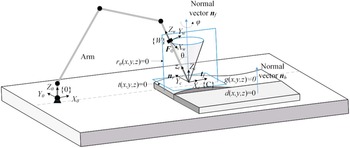
To illustrate our method, we build the model of robot performing tasks as shown in Fig. 2 and define the relevant parameters as follows.
Robot performing constrained tasks on the unknown surfaces. The key idea is to learn the normal vectors on a known plane
 $d({x,y,z}) = 0$
and using the learning results on an unknown surface
 $g({x,y,z}) = 0$
.

The known plane equations and its normal vectors:
 $d\!\left ({x,y,z} \right ) = 0$
,
 $\boldsymbol{n}_h$
.
The unknown surface equations and its normal vectors:
 $f\!\left ({x,y,z} \right ) = 0$
,
 $\boldsymbol{n}_f$
.
Tangent plane equation and tangent vector on the reference plane of the unknown surface:
 $t\!\left ({x,y,z} \right ) = 0$
,
 $\boldsymbol{t}_f$
.
Robot reference plane:
 ${r_\varphi }\!\left ({x,y,z} \right ) = 0$
. The reference plane is formed by
 $Y_w$
and
 $Z_w$
of the coordinate system
 ${W}$
. When the
 ${}^w{F_x} = 0$
, the reference plane is called the initial plane with
 ${r_0}\!\left ({x,y,z} \right ) = 0$
. The force sensor data in initial plane are
 $\boldsymbol{F}_{\textbf{0}}$
.
The normal vector of the reference plane:
 $\boldsymbol{n}_r$
.
Tool orientation:
 $\boldsymbol{z}_t$
.
 $\left \{{{X_C}\;{Y_C}\;{Z_C}} \right \}$
: Constrained coordinate system;
 $\left \{{{X_{\rm{0}}}\;{Y_0}\;{Z_0}} \right \}$
: 0 coordinate system of the robot arm;
 $\left \{{{X_w}\;{Y_w}\;{Z_w}} \right \}$
: Wrist coordinate system of robot arm;
The angle between tool direction and surface normal vector in the reference plane:
 $\theta$
;
The angle between reference plane and initial plane:
 $\varphi$
.
The force sensor data in reference plane:
 ${\boldsymbol{F}}_\varphi$
.
The problem is to use learning method to obtain the relationship between force sensor data and normal vectors as
 \begin{equation} f\,:\,{{\boldsymbol{F}}_\varphi } \to{{\boldsymbol{n}}_h} \end{equation}
2.2. The overall control framework
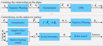
To achieve end-effector force and direction control, we develop the normal vectors learning and generalizing method with adaptive force control and iterative learning control. Figure 3 shows the normal vectors learning and generalizing framework of the robot. The framework consists of two parts, learning the relation on the demonstrated plane and using the relation on the unknown surface. The panda robot control library provides Cartesian space controller and joint space controller. The joint space controller uses PD with gravity compensation. The gravity calculation requires the desired positions of joints which are obtained through inverse kinematics by official open source library provided by Franka. Considering that most of the current industrial arms use joint space control, the joint space controller is chosen. It helps to apply the method to current arms.
Normal vectors learning and generalizing framework of the robot.
 $\boldsymbol{X}_d$
is the desired pose of the end effector.

3. Learning normal vectors
3.1. Learning from a known plane
For different end tools, the force characteristics may be completely different. Force analysis based on specific end tools to determine contact points, surface information, and motion strategies has poor adaptability. Therefore, we learn the relation from the force sensor information to the normal vectors of the surface on the known plane. First, we get the training data.
 $\theta$
is traversed with a certain interval in a reference plane
 ${r_\varphi }\!\left ({u,v} \right ) = 0$
. Recording the force sensor data
 ${\boldsymbol{F}}_\varphi$
and the normal vector
 ${\boldsymbol{n}}_h$
, we can get p group of raw data
 $\left [{\begin{array}{*{20}{c}}{{{\boldsymbol{F}}_\varphi }}&{{{\boldsymbol{n}}_h}} \end{array}} \right ]$
. Through normalization, we can get p group of training data
 $\left [{\begin{array}{*{20}{c}}{{{{\bar{\boldsymbol{F}}}}_\varphi }}&{{{{\bar{\boldsymbol{n}}}}_h}} \end{array}} \right ]$
. Using locally weighted regression, we can get:
 \begin{equation}{{\bar{\boldsymbol{n}}}_h} ={{\bar{\boldsymbol{F}}}^T_\varphi }{\boldsymbol{\omega }} \end{equation}
Compared with linear regression, locally weighted regression increases weight parameters and can smoothly fit nonlinear functions. For p groups of samples
 ${{\bar{\boldsymbol{F}}}_\varphi } = {\left[{\begin{array}{*{20}{c}}{{\bar{\boldsymbol{F}}}_\varphi ^1}&{{\bar{\boldsymbol{F}}}_\varphi ^j}&{\ldots }&{{\bar{\boldsymbol{F}}}_\varphi ^p} \end{array}}\right]^T}$
and
 ${{\bar{\boldsymbol{n}}}_h} = {\left [{\begin{array}{*{20}{c}}{{\bar{\boldsymbol{n}}}_h^1}&{{\bar{\boldsymbol{n}}}_h^j}&{\ldots }&{{\bar{\boldsymbol{n}}}_h^p} \end{array}} \right ]^T}$
, the cost function is established as
 \begin{equation} J ={\sum \nolimits _{j = 1}^p{{\Phi _j}\!\left ({{\bar{\boldsymbol{n}}}_h^j -{{\left ({{\bar{\boldsymbol{F}}}_0^j} \right )}^T}\omega } \right )} ^2} \end{equation}
where
 $\Phi$
is the kernel function. The most commonly used is Gaussian kernel function, and the corresponding weight is shown as the following equation:
 \begin{equation}{{\Phi _j} = {\rm{exp}}\left ({\frac{{\left |{{\bar{\boldsymbol{F}}}_\varphi ^c -{\bar{\boldsymbol{F}}}_\varphi ^j} \right |}}{{ - 2{\sigma ^2}}}} \right ).} \end{equation}
where
 ${\bar{\boldsymbol{F}}}_\varphi ^c$
is the current normalized force data. It follows that,
 \begin{equation}{\boldsymbol{\omega }} = \frac{\bar{\boldsymbol{F}}^T_\varphi {\boldsymbol{\Gamma }}{\bar{\boldsymbol{n}}}_h}{\bar{\boldsymbol{F}}^T_\varphi {\boldsymbol{\Gamma}}{\bar{\boldsymbol{F}}_\varphi}} \end{equation}
where
 ${\boldsymbol{\Gamma }} = \left [{\begin{array}{*{20}{c}}{{\Phi _1}}&{}&{}\\{}&{\ldots }&{}\\{}&{}&{{\Phi _p}} \end{array}} \right ]$
.
3.2. Reference pose estimation
The normal vector of the unknown surface at the contact point can be obtained based on the learned relation on the demonstrated plane. The normal vector can be calculated by
 \begin{equation}{{\boldsymbol{n}}_f} ={{\bar{\boldsymbol{F}}}^T_\varphi }{\boldsymbol{\omega }}. \end{equation}
The tangent vector on the reference plane
 $\boldsymbol{t}_f$
can be calculated by
 \begin{equation}{{\boldsymbol{t}}_f} ={{\boldsymbol{n}}_r} \times{{\boldsymbol{n}}_f}. \end{equation}
The desired pose of the next point of the robotic arm can be estimated as the Eq. (8):
 \begin{equation}{ \left \{ \begin{array}{l}{{\boldsymbol{x}}_d}\!\left ({t + 1} \right ) ={{\boldsymbol{x}}_d}\!\left ( t \right ) + v{t_s}{{\bf{t}}_f}\\[5pt]{{\boldsymbol{n}}_{fd}}\!\left ({t + 1} \right ) ={{{\bar{\boldsymbol{F}}}}^T_\varphi }\!\left ( t \right ){\boldsymbol{\omega }} \end{array} \right .} \end{equation}
where
 $v$
is the speed of the end effector, xd is the desired position of the end effector, and
 $t_s$
is the sampling time. The desired transformation matrix can be calculated as follows:
 \begin{equation}{\boldsymbol{A}}_{0d}^7\!\left ({t + 1} \right ) ={\boldsymbol{A}}_0^7{{\boldsymbol{n}}_{fd}}\!\left ({t + 1} \right ), \end{equation}
 \begin{equation}{\boldsymbol{T}}_{0d}^7\!\left ({t + 1} \right ) = \left [{\begin{array}{*{20}{c}}{{\boldsymbol{A}}_{0d}^7}&\quad {{{\boldsymbol{x}}_d}}\\[3pt] 0&\quad 1 \end{array}} \right ]. \end{equation}
where
 ${\boldsymbol{A}}_0^7$
is the current rotation matrix,
 ${\boldsymbol{A}}_{0d}^7$
is the desired rotation matrix, and
 ${\boldsymbol{T}}_{0d}^7$
is the desired transformation matrix.
4. Adaptive force control and iterative learning
4.1. Adaptive force control
There is a certain deviation between the expected pose obtained from Eq. (8) and the actual pose of the curved surface because of the sampling time, straight line approximation, and the tangent vector estimated error. In order to control the contact force along the surface normal vector, a PID-type adaptive force control method is developed. The adaptive force control law is as follows.
 \begin{equation} \ddot e + \dot e = \left ({{f_e} -{f_d}} \right ) +{K_i}\int{\left ({{f_e} -{f_d}} \right )dt} +{K_d}\!\left ({{{\dot f}_e} -{{\dot f}_d}} \right ) \end{equation}
where
 $f_e$
and
 $f_d$
are the actual normal force and desired normal force, respectively.
 $\dot f_e$
and
 $\dot f_d$
are their differentiations.
 $\dot e$
and
 $\ddot e$
are the velocity error and acceleration error respectively.
 $K_i$
is the integral coefficient.
 $K_d$
is the differential coefficient.
The accumulation of force errors is used as the input of the admittance control in refs. [Reference Duan, Gan, Chen and Dai18, Reference Jung, Hsia and Bonitz19], which can adaptively compensate the environment errors. Results show that the method can achieve high force control accuracy on unknown surfaces. Compared with the method in refs. [Reference Duan, Gan, Chen and Dai18, Reference Jung, Hsia and Bonitz19], the differential term is added and the mass and damping parameters are deleted. The proposed method in this paper can achieve high force control accuracy on geometric unknown surface and reduce the dynamic force error by the differential term. The parameter
 $e$
will be added to the desired position as the following equation:
 \begin{equation}{{\boldsymbol{x}}_r} ={{\boldsymbol{x}}_d} +{\boldsymbol{A}}_0^7{\left [{\begin{array}{*{20}{c}} 0&\quad 0&\quad e \end{array}} \right ]^{\rm{T}}} \end{equation}
where
 ${\boldsymbol{x}}_r$
is the reference position.
 ${\boldsymbol{A}}_0^7$
is the rotation matrix. The reference transformation matrix can be calculated as follows:
 \begin{equation}{\boldsymbol{A}}_{0r}^7\!\left ({t + 1} \right ) ={\boldsymbol{A}}_{0d}^7\!\left ({t + 1} \right ), \end{equation}
 \begin{equation}{\boldsymbol{T}}_{0r}^7\!\left ({t + 1} \right ) = \left [{\begin{array}{*{20}{c}}{{\boldsymbol{A}}_{0r}^7} & \quad {{{\boldsymbol{x}}_r}}\\[4pt] 0&\quad 1 \end{array}} \right ]. \end{equation}
4.2. Iterative learning for direction control
The direction control accuracy will be poor when the friction characteristics are different between the demonstrated plane and the operating surface. In this paper, we developed the iterative learning control for direction control considering the symmetrical repetitive movement. We suppose that the frictions are opposite at the same point during the symmetrical movement of the robot. The deviation angle of the direction control due to the friction force is reversed. Therefore, we design the control law for direction control as the following equation:
 \begin{equation}{ \begin{aligned} {\boldsymbol{n}}_f^{k + 1}\!\left ( t \right ) &= \gamma{\left ({{\bar{\boldsymbol{F}}}_e^{k + 1}\!\left ( t \right ) +{\bar{\boldsymbol{F}}}_e^k\!\left ( t \right )} \right )^T}{\boldsymbol{\omega }}\\ & = 2\gamma \!\left ({{\boldsymbol{n}}_f^k\!\left ( t \right ) + 0.5{{\left ({{\bar{\boldsymbol{F}}}_e^{k + 1}\!\left ( t \right ) -{\bar{\boldsymbol{F}}}_e^k\!\left ( t \right )} \right )}^T}{\boldsymbol{\omega }}} \right ) \end{aligned} } \end{equation}
where the superscript
 $k$
represents the number of iterations.
 ${\bar{\boldsymbol{F}}}_e^k\!\left ( t \right )$
is the normalized end force.
 $\gamma$
is the learning rate. Using Eq. (15), the tool of the robotic arm is gradually aligned with the surface normal vector.
4.3. Stability and convergence analysis of adaptive force control
Assuming the environment model is a pure stiffness model, then the contact force can be obtained by
 \begin{equation}{{f_e}} ={K_e}\!\left ({x -{x_e}} \right ) ={K_e}e\!\left ( t \right ) \end{equation}
where
 $K_e$
is the environmental stiffness,
 $x_e$
is the environmental position, and
 $x$
is the end position of the robot. We can get,
 \begin{equation}{ e\!\left ( t \right ) = \frac{{{f_e}}}{{{K_e}}}\quad \dot e\!\left ( t \right ) = \frac{{{{\dot f}_e}}}{{{K_e}}}\quad \ddot e\!\left ( t \right ) = \frac{{{{\ddot f}_e}}}{{{K_e}}} } \end{equation}
Considering the uncertainty of the environmental location, we use as the estimation of the environmental location. Then,
 \begin{equation} \delta{x_e} ={\hat x_e} -{x_e} \end{equation}
 \begin{equation} \hat e = e + \delta{x_e} \end{equation}
We use the following equation for adaptive force control:
 \begin{equation} \ddot{\hat{e}} + \dot{\hat{e}} = \left ({{f_e} -{f_d}} \right ) +{K_i}\int{\left ({{f_e} -{f_d}} \right )dt} +{K_d}\!\left ({{{\dot f}_e} -{{\dot f}_d}} \right ) \end{equation}
Substituting Eqs. (12) (13) into Eq. (14), we can get
 \begin{equation} \begin{aligned} & \left ({{{\ddot f}_d} -{{\ddot f}_e}} \right ) + \left ({{{\dot f}_d} -{{\dot f}_e}} \right ) + {K_e}\!\left ({{f_d} -{f_e}} \right )\\ & \quad +{K_i}{K_e}\int{\left ({{f_d} -{f_e}} \right ){\rm{dt}}} +{K_d}{K_e}\!\left ({{{\dot f}_d} -{{\dot f}_e}} \right )\\ & \quad = {{\ddot f}_d} +{{\dot f}_d} -{K_e}\delta{{\ddot x}_e} -{K_e}\delta{{\dot x}_e}\\ & \quad = \left ({{{\ddot f}_d} -{{\ddot{\bar{f}}}_e}} \right ) + \left ({{{\dot f}_d} -{{\dot{\bar{f}}}_e}} \right ) \end{aligned} \end{equation}
Let
 $\varepsilon = {f_d} -{f_e}$
,
 $\xi = {f_d} -{\bar f_e}$
and take Laplace transformation of Eq. (15), we can get
 \begin{equation} \begin{aligned} & \varepsilon \!\left ( s \right ){s^2} + \varepsilon \!\left ( s \right )s + {K_e}\varepsilon \!\left ( s \right ) +{K_i}{K_e}\varepsilon \!\left ( s \right )/s\\ & \quad +{K_d}{K_e}\varepsilon \!\left ( s \right )s = \xi \!\left ( s \right ){s^2} + \xi \!\left ( s \right )s \end{aligned} \end{equation}
 \begin{equation} \frac{{\varepsilon \!\left ( s \right )}}{{\xi \!\left ( s \right )}} = \frac{{{s^3} + {s^2}}}{{{s^3} +{K_d}{K_e}{s^2} + {K_e}s +{K_i}{K_e}}} \end{equation}
According to Routh stability criterion, we can get,
 \begin{equation} \begin{array}{*{20}{c}}{{s^3}}&1&{{K_e}}\\{{s^2}}&{{K_d}{K_e}}&{{K_i}{K_e}}\\{{s^1}}&{{K_e} -{K_i}/{K_d}}&0\\ 1&{{K_i}{K_e}}&0 \end{array} \end{equation}
The stability condition is as the following equation.
 \begin{equation} 0 \lt{K_i} \lt{K_d}{K_e} \end{equation}
The convergence can be further analyzed by the final-value theorem.
 \begin{equation} \begin{aligned}{e_s} & = \mathop{\lim }\limits _{t \to \infty } e\!\left ( t \right ) = \mathop{\lim }\limits _{s \to 0} se\!\left ( s \right ) = \mathop{\lim }\limits _{s \to 0} s\!\left ({\varepsilon \!\left ( s \right ) - \xi \!\left ( s \right )} \right )\\ & = \mathop{\lim }\limits _{s \to 0} s\!\left ({\frac{{{s^3} + {s^2}}}{{{s^3} +{K_d}{K_e}{s^2} + {K_e}s +{K_i}{K_e}}}\xi \!\left ( s \right ) - \xi \!\left ( s \right )} \right ) \end{aligned} \end{equation}
When the input is a step signal, that is,
 $\xi \!\left ( s \right ) = \dfrac{1}{s}$
,
 \begin{equation}{e_s} = \mathop{\lim }\limits _{s \to 0} \left ({\frac{{{s^3} + {s^2}}}{{{s^3} +{K_d}{K_e}{s^2} + {K_e}s +{K_i}{K_e}}} - 1} \right ) = - 1 \end{equation}
 \begin{equation} \mathop{\lim }\limits _{s \to 0} s\varepsilon \!\left ( s \right ) = 0 \Rightarrow \mathop{\lim }\limits _{t \to \infty } \varepsilon \!\left ( t \right ) = 0 \end{equation}
Therefore,
 ${F_e}$
tends to
 ${F_d}$
as the time
 ${t}$
is infinite.
4.4. Stability and convergence analysis of iterative learning
The linear time-invariant system can be expressed by
 \begin{equation} \left \{ \begin{array}{l} y\!\left ( t \right ) = pu\!\left ( t \right ) + d\!\left ( t \right )\\[3pt]{u^{k + 1}}\left ( t \right ) = Q\!\left ({{u^k}\!\left ( t \right ) + L{e^k}\!\left ( t \right )} \right ) \end{array} \right. \end{equation}
where
 ${t}$
is the time variable,
 ${k}$
is the number of iterations,
 $u\!\left ( t \right )$
is the input variable,
 $y\!\left ( t \right )$
is the output variable, and
 $d\!\left ( t \right )$
is an external iteration signal. The progressive stability condition of the system is that the initial state of each iteration of the system is identical, and
 \begin{equation} \left |{Q\!\left ({1 - Lp} \right )} \right | \lt 1 \end{equation}
If the system is asymptotically stable and
 $Q = 1$
, then the system error converges gradually to zero [Reference Bristow, Tharayil and Alleyne24]. For iterative learning control algorithm for direction control, it follows that
 \begin{equation}{ \left \{ \begin{array}{l}{\boldsymbol{n}}_f^{k + 1}\!\left ( t \right ) = 2\gamma \!\left ({{\boldsymbol{n}}_f^k\!\left ( t \right ) + 0.5{{\left ({{\bar{\boldsymbol{F}}}_e^{k + 1}\!\left ( t \right ) -{\bar{\boldsymbol{F}}}_e^k\!\left ( t \right )} \right )}^T}\omega } \right )\\{\boldsymbol{F}}_e^k\!\left ( t \right ) = {{\boldsymbol{K}}_e}{{\boldsymbol{x}}^k} -{{\boldsymbol{K}}_e}{\boldsymbol{x}}_e^k \end{array} \right. } \end{equation}
If the environmental location
 $x_e^k = x_e^0$
, progressive stability conditions is
 \begin{equation} \left |{I - \gamma{{\boldsymbol{\omega }}^T}{K_e}} \right | \lt 1 \end{equation}
If
 $Q = 1$
, the system error converges gradually to 0. It follows that
 $\gamma = 0.5$
. Then, we can get
 \begin{equation}{ \left \{ \begin{array}{l}{\bf{n}}_f^{k + 1}\!\left ( t \right ) ={\bf{n}}_f^k\!\left ( t \right ) + 0.5{\left ({{\bar{\boldsymbol{F}}}_e^{k + 1}\!\left ( t \right ) -{\bar{\boldsymbol{F}}}_e^k\!\left ( t \right )} \right )^T}{\bf{\omega }}\\{\bf{F}}_e^k\!\left ( t \right ) = {{\bf{K}}_e}{{\bf{x}}^k} -{{\bf{K}}_e}{\bf{x}}_e^k \end{array} \right. } \end{equation}
Assuming that the force deviation due to friction at the same point in the symmetrical movement of the robotic arm is opposite, that is,
 ${\tilde{\boldsymbol{F}}}_e^{k + 1}\!\left ( t \right ) = -{\tilde{\boldsymbol{F}}}_e^k\!\left ( t \right )$
. It follows that
 \begin{equation}{ \begin{aligned}{\hat{\boldsymbol{n}}}_f^{k + 1}\!\left ( t \right ) & = 0.5{\left ({{\bar{\boldsymbol{F}}}_e^{k + 1}\!\left ( t \right ) +{\bar{\boldsymbol{F}}}_e^k\!\left ( t \right )} \right )^T}{\boldsymbol{\omega }}\\ &={\left ({0.5\left ({{\bar{\boldsymbol{F}}}_d^{k + 1}\!\left ( t \right ) -{\tilde{\boldsymbol{F}}}_e^{k + 1}\!\left ( t \right ) + {\bar{\boldsymbol{F}}}_d^k\!\left ( t \right ) -{\tilde{\boldsymbol{F}}}_e^k\!\left ( t \right )} \right )} \right )^T}{\boldsymbol{\omega }}\\ &={\left ({0.5\left ({{\bar{\boldsymbol{F}}}_d^{k + 1}\!\left ( t \right ) + {\bar{\boldsymbol{F}}}_d^k\!\left ( t \right )} \right )} \right )^T}{\boldsymbol{\omega }} ={\boldsymbol{n}}_f^{k + 1}\!\left ( t \right ) \end{aligned} } \end{equation}
When
 $\gamma = 0.5$
,
 ${\hat{\boldsymbol{n}}}_f^{k + 1}\!\left ( t \right )$
converges gradually to
 ${\boldsymbol{n}}_f^{k + 1}\!\left ( t \right )$
.
4.5. Normal vectors learning and generalizing process
Algorithm 1 gives the process of normal vectors learning and generalization. We first learn the relation between the normal vector and the force sensor information on the demonstrated plane through trajectory planning of the robotic arm. We record the force sensor information and use the locally weighted regression algorithm to obtain the relationship between the normal vector and the force sensor information. All variables are represented in the wrist coordinate system.
The generalization process on the unknown surface uses the strategy learned on the known plane. Based on the force sensor information, the normal vector of the surface is estimated to obtain the expected pose of the robot arm at the next moment. Adaptive force control is used to compensate for surface estimation errors. Iterative learning control is used to eliminate the influence of friction during the symmetrical repetitive motion and further improves the direction control accuracy. After obtaining the reference position of the robotic arm, the desired angle of the joint is obtained through inverse kinematics. The robotic arm can be driven by position control algorithm in the joint space. With these algorithms, the robotic arm can achieve high precision trajectory planning, direction and force control on unknown surfaces.
Normal vectors learning and generalizing process

5. Simulation study
In order to verify the effectiveness of the method, we perform the MATLAB-ADAMS co-simulations using the 7-DOF robot including normal vectors learning simulation, adaptive force control simulation, effects of frictions on direction simulation, and iterative learning simulation. In simulations, numerical method based on pseudo-inverse of Jacobi matrix is adopted to compute the inverse kinematics of the 7-DOF redundant robot. The method yields a unique solution for the robotic arm, which represents the minimum parametric solution. In experiments, we use the official open source library based on ROS provided by Franka to solve the inverse kinematics.
5.1. Simulations of normal vectors learning
In order to verify the normal vectors learning method, we performed simulations of normal vectors learning on the plane. We built the model system with the 7-DOF arm called panda and a plane in ADAMS and implemented the control algorithms in MATLAB. The spherical tool is used in the simulation. We considered the simple case that the range of the angle
 $\theta$
is [–60
 $^{\circ }$
, 60
 $^{\circ }$
] in the initial plane where
 $\varphi$
= 0. The simulation time is 10 s. The length of the steps is 0.01 s. In the learning process on the known plane, the friction is ignored. The force sensor information are measured to obtain 1000 sets of data. The relationship between
 ${\bar{\boldsymbol{F}}}_0$
and
 ${\bar{\boldsymbol{n}}}_h$
is obtained by locally weighted regression. The normal vectors learning process is shown in Fig. 4.
Normal vectors learning process on a plane. The raw data include force and angle are measured. LWR is used to train the relation between force and angle.

5.2. Simulation of adaptive force control
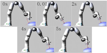
In order to verify the adaptive force control algorithm, we performed simulations of trajectory planning and force control on the curved surface. The curved surface is part of the ellipsoid. The simulation time is 5 s. The sampling time is 0.01 s. The velocity of the end-effector is 0.015 m/s. In the generalization process on the unknown surface, the friction is ignored first. The direction error caused by friction will be discussed in next section.
We carried out the comparative simulations using traditional admittance control in ref. [Reference Qin, De, Zhang and Li16], adaptive admittance control in refs. [Reference Duan, Gan, Chen and Dai18, Reference Jung, Hsia and Bonitz19], and adaptive force control in this paper, respectively. The stiffness is set as
 $K_e=10^6$
N/m. The parameters of traditional admittance control are set as
 $M$
= 1,
 $B$
= 100,
 $K=10^6$
. The parameters of adaptive admittance control are set as
 $M$
= 1,
 $B$
= 20,
 $\eta$
= 0.01. The adaptive force control parameters are set as
 $K_i$
= 1,
 $K_d$
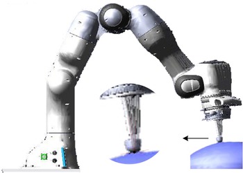
= 0.03. These parameters are chosen by manual adjustment according to the curves. The simulation process of adaptive force control is shown in Fig. 5.
The attitude error and force error are defined as
 \begin{equation}{e_\theta } = \frac{{{{\boldsymbol{n}}_f} \cdot{{\boldsymbol{z}}_t}}}{{\left \|{{{\boldsymbol{n}}_f}} \right \|\left \|{{{\boldsymbol{z}}_t}} \right \|}} \end{equation}
 \begin{equation}{e_F} = \left ({{F_d} -{F_e}} \right )\cos \!\left ({{e_\theta }} \right ) \end{equation}
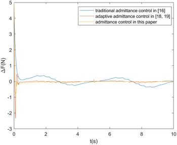
The force error curves are shown in Fig. 6. Through adaptive force control in this paper and adaptive admittance control in refs. [Reference Jung, Hsia and Bonitz19, Reference Yang, Peng, Li, Cui, Cheng and Li20], the force control accuracy can be guaranteed well. The force error is better than 0.1 N. The traditional admittance control has poor force control performance. Compared with the adaptive admittance control in refs. [Reference Duan, Gan, Chen and Dai18, Reference Jung, Hsia and Bonitz19], the adaptive force control does not care mass and damping parameters but
 $K_d$
and
 $K_e$
instead.
The simulation process of adaptive force control on the bulb surface. Three force control methods are used for comparing force tracking performance.

Force error curves comparison using different force control methods. The admittance control in this paper achieves lower force error and initial mutation.

5.3. Effects of frictions on direction
In the simulation of adaptive force control, we ignore the friction. In this part, we carried out the comparative simulations under different friction coefficients.
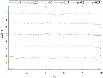
Under different frictions, the configurations of the robotic arm at the same point are shown in Fig. 7. Direction control error curves under different friction coefficients are shown in Fig. 8. From the curves, we can find that the direction control error is not more than 0.4
 $^{\circ }$
without the friction. The higher friction coefficient, the higher force control error. However, the direction deviation caused by friction does not have a great influence on the accuracy of force control. Assuming that the direction error is 16
 $^{\circ }$
and the force control error along the tool direction is 1 N, we can calculate that the force error is 0.96 N according to Eq. (27). This force error deviation caused by frictions is only 0.04 N.
Effects of frictions on direction. As the friction increases, the direction gradually deviates from the normal vector.

Direction control error curves under different friction coefficient. As the friction increases, the direction error gradually becomes larger.

Therefore, although the adaptive force control can achieve high precision force control, it cannot guarantee the direction control performance. In the next part, we use the iterative control method to improve the direction control accuracy in the symmetric repetitive motion.
5.4. Simulations of iterative learning
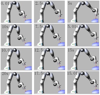
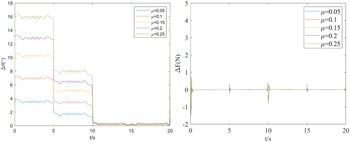
In order to verify the iterative learning for direction control, we performed simulations of trajectory planning and force control on the surface. Different friction coefficients are selected in simulations. The simulation time is 20s containing four symmetric repetitive movements. The simulation process when
 $\mu = 0.25$
is shown in Fig. 9.
The simulation process when
 $\mu = 0.25$
. The first iteration is between 0 and 5 s; The second iteration is between 5 and 10 s; The third iteration is between 10 and 15 s; The fourth iteration is between 15 and 20 s.

The attitude error curves under different friction coefficients using adaptive force control and iterative learning control are shown in Fig. 10 (left). The force error curves are shown in Fig. 10 (right). With the increase of the number of iterations, the accuracy of the direction control is gradually improved. After three iterations, the direction control accuracy is better than 0.5
 $^{\circ }$
. The force control accuracy is better than 0.1 N except for the time when the direction of movement changes. Results show that the force and direction control accuracy are high using the adaptive force control and iterative learning control in the symmetric repetitive movements.
Direction control error and force error curves under different friction coefficients using adaptive force control and iterative learning control.

6. Experimental validation
6.1. Prototype and experiment setup
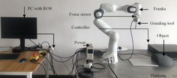
In order to verify the normal vectors learning method, we conducted the experiments of learning the relation on the plane and force control on the curved surface. We established the experimental system as shown in Fig. 11. The system includes the franka robot and its control system, a demonstrated plane, an object with curved surface, a power supply, a 6-axis force sensor, and its data acquisition system. The control algorithms are implemented by C++ programming language in robot operating system (ROS). The control frequency is 1000 Hz. The communication bus is EtherCAT. The video can be seen in ref. [Reference Han34].
The prototype of the system.

6.2. Surface learning process
In surface learning process, the most difficult job is to get good data. The force data need to be mean filtered. In actual robot tasks, the limitations of the joint need to be considered. It is difficult to reach the angle of
 $\pm$
60
 $^{\circ }$
. So, we take
 $\pm$
45
 $^{\circ }$
in the experiment. The robotic arm rotates around the contact point in the initial plane from –45
 $^{\circ }$
to 45
 $^{\circ }$
through fifth polynomial planning. The planning time is 10 s. The force sensor data are sampled every 0.001 s. Due to packet loss, we obtain 9976 samples. Because the robotic arm works in the initial plane, the force along Y axis is almost zero. Each sample is denoted as
 $[F_{ex}, 0, F_{ez}]$
. We process the data as
 $[F_{ex}/F_{ez}, 0, 1]$
and normalize the training data so that
 $\left \|{{{\boldsymbol{F}}_e}} \right \|=1$
. Using locally weighted regression, we can get the relation from the force sensor data to the normal vectors. The learning process is shown in Fig. 12. To better observe the results of the training, we give the fitted curves between the force ratio and angle in Fig. 13. From Fig. 13, the relationship between force and normal vector can be accurately fitted by locally weighted regression. We can use this relationship in the force control test.
The learning process on the plane. The experiment process is same as it in the simulation.

The relationship between force and normal vectors. For simplicity, we used angles instead of normal vectors. The angle and the normal vector are in one-to-one correspondence.

6.3. Fixed-point force and direction control
To verify the proposed method for pose and force control, we first carry out the fixed-point attitude and force control test. According to the relationship between force and normal vector learned on the plane, the desired pose of the arm can be obtained based on the force sensor information. The force control along the tool direction is achieved by the adaptive admittance control proposed in this paper. The desired force along the tool direction is set to 5 N. The adaptive force control parameters are set as
 $K_i=1, K_d=0.03$
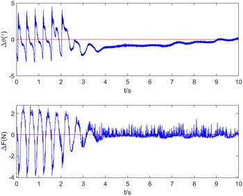
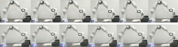
. The experimental process is shown in Fig. 14. The force and direction tracking curves are shown in Fig. 15.
Fixed-point force and direction control. We first carry out the single-point force control and directional control to validate the algorithm. Comparison experiments will be performed on inclined surface and bulb surface.

Force and direction control curves. The red curves are desired values and the blue curves are actual values.

From Fig. 15, we can find that using adaptive force control and the learned relationship between force and normal vector, the force and direction of the end effector can converge to given values. There are oscillations during 0–3 s, which could be caused by the sliding of the robot against the surface and parameters selection. In the fixed-point attitude and force control experiment, the force control accuracy is better than
 $\pm$
0.5 N, and the direction control accuracy is less than
 $\pm$
0.5
 $^{\circ }$
.
6.4. Force and direction control on the bulb surface
In order to verify the proposed method for force and direction control on the curved surface, we carry out the comparative experiments between the traditional adaptive force and direction control in refs. [Reference Oba and Kakinuma10, Reference Armesto, Moura, Ivan, Erden, Sala and Vijayakumar11, Reference Duan, Gan, Chen and Dai18, Reference Jung, Hsia and Bonitz19] and the proposed method in this paper. References [Reference Oba and Kakinuma10, Reference Armesto, Moura, Ivan, Erden, Sala and Vijayakumar11] achieve the direction control by controlling the torque to be zero. References [Reference Duan, Gan, Chen and Dai18, Reference Jung, Hsia and Bonitz19] achieve the adaptive force control by the accumulation of force errors. In the force and direction control test, the arm moves repeatedly on the curved surface. According to the relationship between force and normal vector learned on the plane, the desired pose of the arm can be obtained based on the force sensor information. The desired force along the tool direction is set to 5 N. The parameters of traditional admittance control are set as
 $M=1, B=100, K=10^6$
. The adaptive force control parameters are set as
 $K_i=1, K_d=0.03$
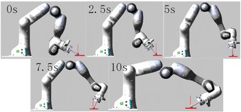
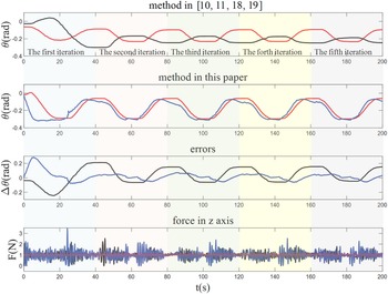
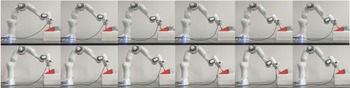
. The experimental process is shown in Fig. 16. The force error curve and direction error curves are shown in Fig. 17. Using adaptive admittance control in refs. [Reference Duan, Gan, Chen and Dai18, Reference Jung, Hsia and Bonitz19], the force error is about
 $\pm$
1 N. Using force-based direction control in refs. [Reference Oba and Kakinuma10, Reference Armesto, Moura, Ivan, Erden, Sala and Vijayakumar11], the direction control error is about
 $\pm$
5
 $^{\circ }$
. Using adaptive force control is this paper, the force control accuracy is about
 $\pm$
0.6 N. In the first two iterations, the direction angle is about
 $\pm$
5
 $^{\circ }$
, which is consistent with the results of the method in refs. [Reference Oba and Kakinuma10, Reference Armesto, Moura, Ivan, Erden, Sala and Vijayakumar11]. After the fourth iteration, the angle error is reduced to
 $\pm$
0.5
 $^{\circ }$
. The reason for the big initial error is due to friction. This is the main limitation of the proposed method in this paper.
Force and direction control on the bulb surface. The six images above are obtained using the method in [Reference Oba and Kakinuma10, Reference Armesto, Moura, Ivan, Erden, Sala and Vijayakumar11, Reference Duan, Gan, Chen and Dai18, Reference Jung, Hsia and Bonitz19]. The six images below are obtained using the proposed method in this paper.

Force and direction tracking curves. The red curves are desired values, the black curves are actual values produced by the method in refs. [Reference Oba and Kakinuma10, Reference Armesto, Moura, Ivan, Erden, Sala and Vijayakumar11, Reference Duan, Gan, Chen and Dai18, Reference Jung, Hsia and Bonitz19], and the blue curves are actual values produced by the proposed method in this paper.

Trajectory planning and force control on the inclined surface. The six images above are obtained using the method in refs. [Reference Oba and Kakinuma10, Reference Armesto, Moura, Ivan, Erden, Sala and Vijayakumar11, Reference Duan, Gan, Chen and Dai18, Reference Jung, Hsia and Bonitz19]. The six images below are obtained using the proposed method in this paper.

6.5. Force and direction control on the inclined surface
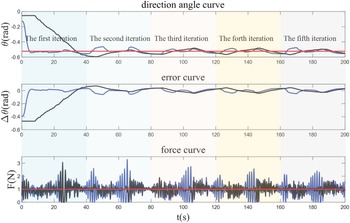
In order to fully verify the proposed method for trajectory planning and force control on the inclined surface, we carry out the comparative experiments between the traditional adaptive force and direction control in refs. [Reference Oba and Kakinuma10, Reference Armesto, Moura, Ivan, Erden, Sala and Vijayakumar11, Reference Duan, Gan, Chen and Dai18, Reference Jung, Hsia and Bonitz19] and the proposed method in this paper. In the force and direction control test, the arm moves repeatedly on the inclined surface. According to the relationship between force and normal vector learned on the plane, the desired pose of the arm can be obtained based on the force sensor information. The desired force along the tool direction is set to 1 N. The parameters are set as the same as them in the trajectory planning and force control experiment on the bulb surface. The experimental process on inclined surface is shown in Fig. 18. The force error curve and direction error curves on inclined surface are shown in Fig. 19. From Fig. 18, we can find that when using adaptive admittance control in refs. [Reference Duan, Gan, Chen and Dai18, Reference Jung, Hsia and Bonitz19], the force error is about
 $\pm$
1N. Using force-based direction control in refs. [Reference Oba and Kakinuma10, Reference Armesto, Moura, Ivan, Erden, Sala and Vijayakumar11], the direction control error is about
 $\pm$
0.2 rad. Using adaptive force control is this paper, the force control accuracy is about
 $\pm$
1 N. The direction control error is about
 $\pm$
0.1 rad. From Fig. 19, we can find that when using adaptive admittance control in refs. [Reference Duan, Gan, Chen and Dai18, Reference Jung, Hsia and Bonitz19], the force error is about
 $\pm$
1 N. Using force-based direction control in refs. [Reference Oba and Kakinuma10, Reference Armesto, Moura, Ivan, Erden, Sala and Vijayakumar11], the direction control error is about
 $\pm$
0.1 rad. The settling time is about 35s. Using adaptive force control is this paper, the force control accuracy is about
 $\pm$
2 N. The direction control error is about
 $\pm$
0.1 rad. The settling time is about 5s.
Force error and direction control error curves on the inclined surface. The red curves are desired values, the black curves are actual values produced by the method in refs. [Reference Oba and Kakinuma10, Reference Armesto, Moura, Ivan, Erden, Sala and Vijayakumar11, Reference Duan, Gan, Chen and Dai18, Reference Jung, Hsia and Bonitz19], and the blue curves are actual values produced by the proposed method in this paper.

From Figs. 18 and 19, the method in refs. [Reference Oba and Kakinuma10, Reference Armesto, Moura, Ivan, Erden, Sala and Vijayakumar11] has a long settling time, which lead to a large delay on the bulb surface experiment. The proposed has short settling time and perform better. In five iterations, the angle error is decreasing, but it is not obvious. The reason for the big initial error is due to friction. The reason why the iteration effect is not obvious is the noise of the force sensor, which lead to the low accuracy of surface normal vector measurement. This is the main limitation of the proposed method in this paper.
7. Conclusion
The normal vectors learning algorithms with adaptive force control and iterative learning for end-effector force and direction control on the unknown surface are developed. By learning the relation from the force sensor data to the normal vectors on the demonstration plane, the robot could estimate the surface normal vectors. Then, the pose prediction algorithm is used to generalize the reference pose. The PID-type adaptive force control is proposed to improve the force control accuracy under the surface geometric estimation error. Considering different friction characteristics that cause direction control errors, we developed the iterative learning algorithms in symmetric repetitive movements. In order to verify the effectiveness of the method, we performed the MATLAB-ADAMS co-simulations using the 7-DOF robot. Results show that the normal vectors learning strategy with adaptive force control and iterative learning can solve the problem of high-precision force tracking and direction control on unknown surfaces.
(1) Compared with the methods in refs. [Reference Jiang, Xu and Xie5–Reference Armesto, Moura, Ivan, Erden, Sala and Vijayakumar11], this paper does not need force analysis, simple contact model, and simple friction model.
(2) Compared with the methods in refs. [Reference Oba and Kakinuma10–Reference Qin, De, Zhang and Li16], this paper considers the tool alignment accuracy due to friction using iterative learning control.
(3) Compared with the traditional admittance control in ref. [Reference Hogan17], the adaptive force control can improve the force control accuracy. Compared with the adaptive admittance control in refs. [Reference Duan, Gan, Chen and Dai18, Reference Jung, Hsia and Bonitz19], the adaptive force control only needs to adjust two parameters including
 $K_i$
and
 $K_d$
.
However, this method also has some limitations. From experiments, we find if robot moves fast, the deviation of the robot posture from the surface normal vector is big. This is because the fast motion will make the tangential friction force larger. The curvature of the object is too large also affects the effectiveness of the method. There are limits to the end speed of the robotic arm. The curvature of the object is too large, and the robotic arm cannot move too fast, otherwise it will be difficult to track on. For example, for a machining task, the method of this paper may no longer be applicable due to its excessive tangential forces. The learning relationship between the normal vector of a surface and the contact force cannot be used anymore.
8. Discussion
We address the problem of simultaneously control end-effector force and direction with six-axis force sensor mounted at the end of the arm. In order to control force, the PID-type adaptive force control method is proposed. In order to control direction, the idea of learning the relation between normal vectors and force sensor data is presented. Moreover, we consider the effect of friction on direction control and propose iterative learning to reduce the error. We validate the proposed method by both comparative simulations and experiments with force and direction control tasks. To this end, we show that the proposed method can achieve good force and direction control accuracy on unknown surfaces.
It is important to emphasize the fact that the method proposed in this paper does not effectively verify the real polishing and grinding process. (1) Simulation data do not really represent force-based tasks, which have to cope with a lot of force sensor noise. The frictions are supposed to be opposite at the same point during the symmetrical movement of the robot, which is different from the actual situation. More experiments should be conducted to fully verify the proposed method. (2) Although preliminary results are obtained by force and direction control experiments on both bulb and inclined surfaces, the experiments did not fully consider the real process of grinding, such as grinding trajectory, grinding force, grinding accuracy, grinding speed, and real grinding tool. Experiments rely on constant force patterns with very low values, that is, 1 N. This is because when we try to give high expected values, the franka robot may stop because of “trajectory discontinuity error.” We find that there exists jitter limits in franka and we cannot turn it off even if we sought franka technical support. We can solve it by increasing the impedance parameter and reducing the expected force. The high impedance parameters lead to long convergence time in Fig. 15, which might limit its implementation in real scenarios. Better results such as higher contact forces and quicker convergence time will be achieved if other industrial robot is used for the actual grinding process. (3) To ensure real-time performance, we simplify LWR method to compute unknown surface normal vectors on RT-linux system in experiments. If a hard real-time system and an individual thread is used, less packet loss and latency can be achieved. (4) It is worth noting that the deviation of the angle at the initial moment due to friction poses a potential safety issue. The limit of joint angle should also be set artificially in the actual grinding experiment.
Due to time constraints and available equipment, we regret that we do not continue to refine the experimental validation. I hope the above suggestions will be helpful to interested readers.
Author contributions
Liang Han designed the study. Yu Gao and Lei He carried out the experiments. Wenfu Xu calibrated English expression. Liang Han and Yunzhi Huang wrote the article.
Financial support
This work was supported by Supported by National Natural Science Foundation of China (Grant No. 62203147), the State Key Laboratory of Robotics and Systems (HIT) (Grant No. PA2022GKSK0004), and the Fundamental Research Funds for the Central Universities of China (Grant No. JZ2022HGTA0339).
Competing interests
The authors declare no Competing interest exist.
Ethical standard
Not applicable.