Introduction
In recent years, there has been a rise in natural disasters as well as man-made disasters such as cyclones, earthquakes, tsunami floods, terrorist attacks, and accidents. To rescue people from such disasters, Public Protection and Disaster Relief (PPDR) communication network was developed and organized by the government and agencies [Reference Doumi1]. Federal communications commission allocated frequency range from 4.94 to 4.99 GHz for public safety band. Satellite communication also plays a significant role in emergency conditions. The voice and data communications are made by utilizing the satellites. Mobile satellite service (MSS) and Indian National Satellite System or INSAT are some of the services operated for rescue operations. INSAT is a geostationary satellite launched by ISRO that is used for many purposes, but the important usage is a search and rescue operation. Reliable communication infrastructure is the major part of an emergency system, which allows the operator to rescue the people by collecting the data from the monitoring devices in the disaster area [Reference Chiti, Fantacci, Maccari, Marabissi and Tarchi2].
Reliable communication requires an antenna with small size, lightweight, ease of fabrication, and supports multiband operation. Patch antennas are suitable for achieving the said requirements [Reference Balanis3], while the disadvantage is it does not support multiband. Nowadays, wireless communication devices such as laptops, tablet, and smartphones should be able to support multiple applications with compact size. A large number of works has been reported for realizing a compact antenna with multiband operation using several techniques including applying different fractal geometries to the antenna [Reference Ganesan and Iyampalam4], employing various feeding techniques [Reference Rajeshkumar, Rengasamy, Naidu and Kumar5, Reference Reddy and Sarma6], utilizing self-complementary structure [Reference Ganesan, Kavitha and Paulkani7], and using substrate integrated waveguide (SIW) [Reference Kumar, Saravanakumar and Raghavan8]. Among these techniques, a fractal is one of the most popular techniques due to its properties of self-similarity and space-filling which provide multiband behavior and small size.
In recent days, several antennas are developed based on the fractalizing techniques which include Koch snowflake fractal [Reference Sivasundarapandian and Suriyakala9], Sierpinski fractal [Reference Hwang10–Reference He, Li, Zhai, Dang, Liang and Liu12], periwinkle flower-shaped fractal [Reference Elavarasi and Shanmuganantham13], “X” shaped fractal [Reference Gupta, Joshi and Khanna14], Minkowski curve [Reference Mishra and Mangaraj15, Reference Behera and Vinoy16], and spidron fractal [Reference Hwang, Kim and Nguyen Thi17] for various wireless applications. However, to the best of the authors' knowledge, a limited number of antennas is reported by the researcher for emergency management. A capacitive feed stepped T-shape patch antenna is designed for US public safety band and long term evolution [Reference Mopidevi, Rodrigo, Kaynar, Jofre and Cetiner18]. The dimension of the stated antenna is 193.75 × 168.75 mm2.
The antenna in [Reference Mopidevi, Damgaci, Rodrigo, Jofre and Cetiner19] operated in quad-band with a size of 160 × 178 mm2. These antennas are larger in size. Therefore, fractal geometry is utilized to attain a compact size [Reference Lizzi, Azaro, Oliveri and Massa20–Reference Kakkar, Kamal and Singh22]. The design of a multiband antenna based on the perturbed Sierpinski geometry is reported in [Reference Lizzi, Azaro, Oliveri and Massa20]. In addition to that, the particle swarm optimization technique is carried out for synthesizing antenna parameters. Fibonacci word fractal antenna with two rectangular slots is stated in [Reference Singh and Singh21] for public safety applications. Whale optimization is implemented for enhancing efficiency. An “I” shaped fractal antenna is designed by subtracting two parallel edges from the center of the rectangular patch. It is inspired by the Sierpinski carpet structure [Reference Kakkar, Kamal and Singh22]. The previously developed antenna's structure is complicated to design and larger.
In this paper, design, simulation, and analysis of a complementary Sierpinski Knopp (CSK) fractal antenna are reported for MSS, PPDR, and INSAT C band communication. In the section “Numerical formulation”, the numerical formulation and generation of the Sierpinski Knopp curve for CSK antenna are described. The section “Antenna design methodology” expresses the antenna design methodology and parametric analysis of the design variables. The discussion of the simulated and measured results is elaborated in the section “Measured results and discussion” and finally, the work is concluded in the last section.
Numerical formulation
The monopole antenna is widely used as the most popular antenna due to its small size and ease of fabrication. In this work, a square monopole antenna is taken as the basic design for constructing the projected fractal antenna. The parameters of the monopole antenna can be determined by using the following formula [Reference Balanis3]


Here, W and L are the width and length of the patch, c is the velocity of light (c = 3 × 10⁸ m/s), fr is the resonance frequency, ξr is the dielectric constant, h is the thickness of the substrate, and ΔL is the incremental length due to the fringing.
Iterated Function System (IFS)
The IFS is a mathematical method to generate the fractal structure by describing scaling, rotation, and transformation of the kernel structure. It uses the set of self-affine transformations for fractal geometry generation. The IFS matrix of the proposed CSK fractal can be expressed as [Reference Sagan23]


Let us assume that P 1, P 2, … , Pn are the series of linear self-affine transformations and S be the initial structure. The final geometry is obtained by uniting all four transformations. It can be expressed as

The higher-order iterations of the fractal are achieved by repeating this process. The IFS is also referred to as a multiple reduction copy machine. The fractal similarity dimension (D) can be calculated as [Reference Singh and Singh21]

where n is the number of copies and f is the scaling factor. In the case of the Sierpinski Knopp curve, n = 4 and f = 1/2. The fractal dimension is 2 for the proposed CSK antenna.
Antenna design methodology
Antenna configuration
The projected CSK fractal antenna is assembled on the FR4 dielectric material with a volume of 35 × 35 × 1.6 mm3. Figures 1(a) and 1(b) show the front and 3D view of the proposed CSK fractal antenna. The novelty of the proposed antenna lies in the antenna radiating structure. Also, a slot-loading technique is employed in order to increase the number of operating bands. The structure consists of the Sierpinski Knopp curve inspired square monopole antenna on the upper side of the substrate and partial ground plane on the flipside.
Geometry of the proposed CSK fractal antenna. (a) Front view, (b) 3D view.

The microstrip feed line is bonded to the female SMA connector having 50Ω impedance for electrifying the antenna. The motivation of such fractal geometry is to increase the electrical length and bandwidth of the antenna. The variables are assigned to each element of the antenna for parametric analysis as follows: Ls – length of the substrate, Ws – width of the substrate, h – thickness of the substrate, Lp – length of the microstrip patch, Wp – width of the microstrip patch, Lg – Length of the ground plane, Wg – width of the ground plane, Lf – length of the microstrip feed line, and Wf – width of the microstrip feed line. The distance between the feed line and edge of the patch is denoted by W 1.
To achieve the desired results, the dimensions of the substrate material, ground plane, microstrip patch, and feed line have been optimized by performing the parametric analysis. The performance metric of the antenna is investigated by utilizing the ANSYS HFSS. The values of the design variables are listed in Table 1, which yields the optimum results. The square of dimension 25 × 25 mm2 has been chosen as a kernel to create the geometry of the projected fractal antenna. Initially, the square patch is fragmented into two isosceles triangles. The various iteration stages in the development of the proposed CSK fractal antenna from the basic design to 3rd iteration is depicted in Fig. 2.
Iteration Stages of fractal antenna. (a) Basic design, (b) 0th iteration, (c) 1st iteration, (d) 2nd iteration, (e) 3rd iteration.

Dimensions of the CSK antenna

Figure 2(a) shows the square monopole antenna which is modified in such a way to achieve the desired frequency bands by using fractal geometry. As seen in Fig. 2(b), a square with an area of 8.83 × 8.83 mm2 has been placed in the middle and rotated by 90°. The resulted diamond-shaped patch is etched from the basic square monopole, which is named as 0th iteration. For the first iteration, the square monopole is sliced into four smaller squares. The diamond-shaped patch is scaled down by 2 and located in the middle of each four squares. The edges of all diamond-shaped patches are joined and removed from the kernel. Antenna design at the end of the first iteration is displayed in Fig. 2(c). This recursive process is repeated for obtaining the second and third iterations of the fractal antenna that are depicted in Figs 2(d) and 2(e), respectively.
Parametric study
The parametric analysis of the fractal antenna has been carried out for achieving better performance. In this study, the size of the substrate, ground plane, feed line, and square patch is considered for the parametric analysis. The S 11 at different iteration levels from basic design to iteration-4 of the fractal antenna is shown in Figs 3(a) and 3(b). The antennas in the basic design and 0th iteration have not an effective S 11, which is higher than −10 dB. In the first iteration, antenna resonates at 6.28 GHz with −15.8 dB reflection coefficient.
Effect on S 11 at different iteration levels. (a) Basic design, Iteration-0, Iteration-1, Iteration-2 and Iteration-3, (b) Iteration-4.

The dual resonance appears at the second iteration where the S 11 values are −15.02 dB at 2.42 GHz and −16.88 dB at 3.23 GHz. The required triple band with improved S 11 and bandwidth is achieved by the suggested fractal antenna in the 3rd iteration. Reflection coefficients are reduced to −19.6, −24, and −17.3 dB at the corresponding resonant frequencies of 1.94, 4.95, and 6.41 GHz, respectively.
Table 2 presents the comparative characteristics of the antenna at various iterations. It is noted that the number of resonant frequency increases as the number of iterations increases because of the fractal structure.
Comparative characteristics of antenna at various iterations

The bandwidth and gain of the antenna are decreased at some frequency bands and voltage standing wave ratio (VSWR) is acceptable (VSWR≤2) by increasing the iteration. When doing it up to the 3rd iteration, the performance such as bandwidth and gain is found to be better than the results obtained during 4th iteration. On the other hand, it is observed that moving from 3rd iteration to 4th iteration, the operating frequency is deviating and the antenna becomes quite complicated and its fabrication becomes difficult. Therefore, the number of iteration in the proposed work is limited to 3rd iteration.
The geometrical parameters such as LS, WS, LP, WP, Lg, LF, WF, and h are varied individually while the other parameters are remaining constant. The length (LS) and width (WS) of the substrate are changed from 31 to 35 mm. The slight change in the substrate length (LS) alters the resonance behavior of the antenna. The S 11 versus frequency for different LS and Ws is shown in Figs 4(a) and 4(b), respectively. The required triple-band resonance characteristics with better performance are observed at LS = WS = 35 mm. From Fig. 4(b), it can be found that the frequency is shifted from 6 to 4.95 GHz due to changes in the substrate width (WS).
Effect on S 11 with variation of (a) length of the substrate LS, (b) width of the substrate WS.

The patch length LP and width WP are varied from 21to 25 mm with a step of 1 mm. The impedance matching is found well at LP = 25 mm.
As seen in Fig. 5(a), the antenna resonates at the higher frequencies above 6 GHz for the values of LP from 21 to 24 mm. The antenna has dual-band operation for the values of WP from 21 to 24 mm and triple-band operation at 25 mm which is presented in Fig. 5(b).
Effect on S 11 with variation of (a) length of the patch LP, (b) width of the patch WP.

In a further study, the feed line length (LF) is varied from 5 to 9 mm with an interval of 1 mm and the effect on S 11 is depicted in Fig. 6(a). The optimum value is chosen as 5 mm because of its resonance at 4.95 GHz, which is the required band for PPDR applications. The effect on S 11 with respect to various feed width (WF) is presented in Fig. 6(b). The resonant frequency is shifted to the lower side as WF increases. It is noted that the antenna has good performance at 3 mm. The substrate thickness (h) also plays an important role in the antenna design. Figure 7(a) shows the impact on the S 11 by varying h. A poor impedance matching is perceived for the values of h ranges from 1 to 1.6 mm. Antenna impedance is well matched at 1.6 mm. Therefore, the value of 1.6 mm is selected as the thickness of the substrate (h). Figure 7(b) shows the effect on S 11 against frequency for different ground plane length (Lg). The better result is attained at 6.5 mm.
Effect on S 11 with variation of (a) length of the feed line L F, (b) width of the feed line W F.

Effect on S 11 with variation of (a) substrate thickness h, (b) length of the ground plane Lg.

All the geometrical parameters of the proposed CSK fractal antenna are chosen according to the parametric analysis for achieving optimum results.
Measured results and discussion
The prototype of the projected antenna is fabricated using the FR4 substrate with the dielectric constant (εr) of 4.4, thickness (h) of 1.6 mm, and loss tangent (δ) of 0.002. The photo etching technique is used for fabricating the antenna. In the fabrication process, the cover of the photoresist of the FR4 board is removed. Then, the transparent mask of the antenna geometry is placed over the FR4 board. The transparent mask is the image of the .dxf file, which is obtained from Ansys HFSS. Next, the FR4 board is exposed to ultra-violet (UV) light. In the final stage, the etching process is performed by placing the FR4 board in a ferric chloride solution. In order to remove unwanted photoresist material, the board is rinsed with acetone. After that, the SMA connector is soldered to the fabricated antenna.
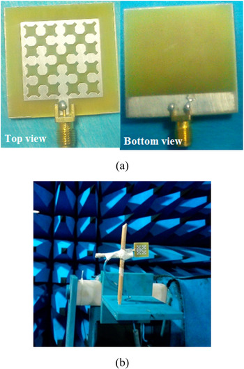
The fabricated antenna is measured by using Agilent vector network analyzer (VNA) under an anechoic chamber in order to validate the results, which are obtained through simulation. The fabricated CSK fractal antenna and the measurement setup in the anechoic chamber are illustrated in Figs 8(a) and 8(b), respectively.
(a) Fabricated CSK fractal antenna, (b) measurement setup in the anechoic chamber.

Figure 9 shows the simulated and measured S 11 plot against frequency. It is found that the impedance bandwidths are 30 MHz (1.4% centered at 2.08 GHz), 110 MHz (2.2% centered at 4.93 GHz), and 870 MHz (13.4% centered at 6.46 GHz), respectively. Thus, the suggested CSK fractal antenna can cover the emergency management system that is PPDR (4.90–5.01 GHz), MSS (2.07–2.10 GHz), and INSAT C band (5.87–6.74 GHz) applications. The simulated and measured data of the projected CSK fractal antenna are listed in Table 3. There is a deviation between the results obtained through simulation and measurement because of the losses occurred during the fabrication and soldering of the SMA connector to the antenna.
Simulated and measured S 11.

Comparison of simulated and measured data of projected CSK fractal antenna

The distributions of the current on the fractal antenna at resonant frequencies are depicted in Fig. 10. The high current density implies the high coupling while the low current density indicates less coupling. The maximum current density is distributed near the feed line and the edges of the patch at 2.08 GHz that is shown in Fig. 10(a). As seen in Fig. 10(b), the current density is highly concentrated on the lower side, left, and right side of the patch at 4.93 GHz. The coupling is high at 6.46 GHz where the maximum current is found on the ground plane as well as the lower half of the patch that is presented in Fig. 10(c).
Current distribution at (a) 2.08 GHz, (b) 4.93 GHz, and (c) 6.46 GHz.

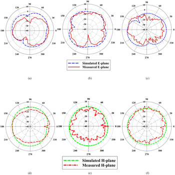
The radiation pattern is obtained by rotating the antenna angle (θ) from 0° to 360°. For the corresponding operating frequencies, the simulated and measured E-plane radiation pattern is shown in Figs 11(a)–11(c). It is observed that the antenna exhibits a doughnut-shaped pattern in E-plane.
Simulated and measured radiation pattern in E-plane at (a) 2.08 GHz, (b) 4.93 GHz, and (c) 6.46 GHz; H-plane at (d) 2.08 GHz, (e) 4.93 GHz, and (f) 6.46 GHz.

Figures 11(d)–11(f) show the H-plane radiation pattern obtained through simulation and measurement, which reveals that the antenna has an omnidirectional radiation pattern across the corresponding operating bands.
Gain is one of the important factors in the design of an antenna. It provides the maximum energy radiation in a particular direction. The 3D gain plot at 2.08, 4.93, and 6.46 GHz is depicted in Figs 12(a)–12(c), respectively. The projected CSK fractal antenna has a gain of 3.62 dBi at 2.08 GHz, 3 dBi at 4.95 GHz, and 3.76 dBi at 6.46 GHz. The comparison of the CSK fractal antenna with the existing fractal antenna is summarized in Table 4. It is noted from Table 4 that the proposed antenna is compact size in comparison with the antennas reported in [Reference Hwang, Kim and Nguyen Thi17, Reference Mopidevi, Rodrigo, Kaynar, Jofre and Cetiner18, Reference Mopidevi, Damgaci, Rodrigo, Jofre and Cetiner19, Reference Singh and Singh21].
3D gain plot at (a) 2.08 GHz, (b) 4.93 GHz, and (c) 6.46 GHz.

Comparison of the projected fractal antenna with the earlier antennas in the literature.

a Not available.
The antennas stated in [Reference Malik, Kalaria and Kartikeyan11, Reference Mishra and Mangaraj15, Reference Behera and Vinoy16, Reference Lizzi, Azaro, Oliveri and Massa20] have compact size but the bandwidth of those antennas is less than the proposed CSK fractal antenna. In [Reference Mopidevi, Damgaci, Rodrigo, Jofre and Cetiner19], an antenna has four resonant frequencies, which is higher than the proposed antenna but the size is larger and gain is not reported. The projected CSK antenna exhibits triple-band whereas the other antennas have single and dual bands. Based on the above discussion, it can be seen that the proposed antenna is novel and useful for wireless applications include MSS, INSAT C band, and public safety band.
Conclusion
A triple-band CSK fractal antenna is proposed for wireless applications dedicated to the emergency management system, MSS, and INSAT C band applications. The prototype of the CSK is fabricated and tested. It is observed from the measurement results that the antenna has three operating frequencies of 2.08, 4.93, and 6.46 GHz with a small size 35 × 35 × 1.6 mm3. Doughnut-shaped and omnidirectional radiation patterns are obtained in E- and H-plane. The measured results are in good accordance with the simulation results. Maximum bandwidth and gain of 870 MHz and 3.76 dBi have been observed at 6.46 GHz.
Acknowledgement
The authors wish to thank the Mepco-Agilent R&D Centre of Excellence in RF Circuit and Antenna Design, Mepco Schlenk Engineering College, Sivakasi for the support in carrying out this research work.
 Paulkani Iyampalam received her B.E degree in Electronics and Communication Engineering from Kings Engineering College, Chennai, India and M.E degree in Communication Systems from Mepco Schlenk Engineering College, Sivakasi, Tamil Nadu, India. Now, she is working towards her Ph.D. at Mepco Schlenk Engineering College, Sivakasi, Tamil Nadu, India. She is an associate member of the Institution of Engineers (India). Her research interest includes metasurface antennas, smart antennas and fractal antennas.
 Indumathi Ganesan has 21 years of experience in teaching and research at Mepco Schlenk Engineering College, India. She received her B.E degree in Electronics and Communication Engineering and M.E degree in communication systems from Madurai Kamaraj University, Madurai, India. She completed her Doctoral program in the field of Wireless Communication from Anna University, Chennai, India. She is working as a professor in the Department of Electronics and Communication Engineering in Mepco Schlenk Engineering College, Sivakasi, Tamil Nadu, India. She is a lifetime member of ISTE, IEI and FIETE. Her main research interests are wireless communication, digital signal processing and antenna design. She has published 90 research papers in various international, national journals, and conferences.