Introduction
Rectangular and circular waveguides have been used since World War II and are still used. These waveguide-based elements have wide applications in various frequency bands ranging from 1 to 1000 GHz. Phased array antennas are used in RADAR, satellite communication, broadcasting, space probe communication, weather research, human-machine interface, 5G and Wi-Fi. Multiport power dividers or combiners are used as a feeding network for phased array antennas. As multiple input multiple output techniques are used in many applications, channel interference has become a significant issue.
A literature survey on channel interference reveals that many authors have described it in coaxial cables, microstrip lines and optical fiber cables [Reference Lafata1–Reference Balasubramanian, Miyazaki and Kondo3]. Coupling of power at waveguide joint has been analyzed for X-band and Ku-band only [Reference Panda and Chakraborty4–Reference Sharma and Panda6]. Many research studies are going on longitudinal waveguides for high power transmission and radiation. For high-frequency applications, it is necessary to use a waveguide-based component. When a two-dimensional array with a power divider through flange is joined, there may be a gap due to faulty workmanship. This gap is unwanted, may cause coupling of power to an adjacent channel. So, at higher frequency bands, channel interference should be analyzed.
An excellent technique for the analysis of waveguide-based components is multi cavity modeling technique (MCMT). It was proposed by Vengadarajan [Reference Vengadarajan7]. This technique analyzes slot antenna, open-ended waveguide, to estimate EMC/EMI at faulty joint and directional coupler. Further, E-plane Tee, H-plane Tee, power dividers and combiners have been analyzed using the multi-cavity modeling technique by Das, Chakraborty and Panda [Reference Das, Chakraborty and Chakrabarty8–Reference Panda12]. More work has been done to analyze waveguide-based networks for high frequency [Reference Panda and Chakraborty13].
This paper presents the analysis of coupling at E-plane waveguide joints using the multi-cavity modeling technique. Generally, in this technique, the equivalent magnetic current density replaces all the opening and gaps of the waveguide structure. So it becomes easy to analyze the structure using magnetic field integral equation (MFIE). Here four waveguides are used to model this structure, and the gap is considered as a cavity. Further, the tangential component of the magnetic field scattered inside the waveguide and cavities are determined using the procedure outlined in [Reference Panda12], and the continuity of the tangential component of the magnetic field at coupling aperture is also considered. Now to solve for the electric field at the window aperture, the method of the moment is used. By using basis functions, this method converts all the integral equations into matrix equations. By knowing the aperture fields, reflection and transmission coefficients are being estimated. As coupling regions are of arbitrary dimension, the cross-polarization component has been considered in the analysis. Other higher bands can also be analyzed using MCMT.
Theory
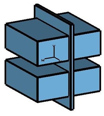
At the beginning for the analysis of co-channel interference, a theoretical model has been prepared using two-channel E-plane waveguides, shown in Fig. 1. The CST simulated three-dimensional view is shown in Fig. 2. It shows that the structure has four waveguide regions wvg-1 to wvg-4 and one cavity gap. It also has four interfacing apertures (A1-A4).
E-plane two-channel waveguide joint in terms of cavity, waveguides, different regions, and magnetic current at the apertures.

CST simulated a 3D view of two-channel E-plane waveguides with a gap.

When the structure is fed at its input port, field distribution is established on the apertures. The equivalent magnetic current densities replace the interfacing apertures between different regions. There are four magnetic current densities M1 to M4 as per four apertures A1 to A4 [Reference Harrington14]. These are considered sources and can be obtained by modal expansion method for waveguide regions (Wvg-1 to Wvg-4) and using cavity Green's function for cavity region. By applying the continuity of the tangential component of the magnetic field across the apertures, boundary conditions can be found between different regions as given in [Reference Sharma and Panda6].
Fields are represented over Y-Z plane. Here Y-component of the incident magnetic field at the aperture is a dominant TE10 mode and is given by

As electric field distributions are unknown, but can be expressed as a weighted sum of sinusoidal basis functions, which can be given as

Here $E_p^{i, y/Z}$ are the unknown weights and $e_p^{i, y/z}$
 are the sinusoidal basis function which is given by:


In the above expressions L = a, W = b, where 2a = 10.668 mm and 2b = 4.318 mm, s = 1.02 mm and 2s is the distance between wvg-1 and wvg-4.
The aperture field distributions can be determined by the knowledge of unknown weight $E_p^{i, y/z}$ . Apertures are representing the boundary between different regions as shown in Fig. 1. For each aperture, there are two boundary conditions, corresponding to the two tangential components (Y and Z). These boundary conditions have been solved using Galerkin's specialization of the method of the moment [Reference Harrington15]. In this method, weighting functions $w_q^{i, y/z} ( {x, \;y, \;z} )$
 are assumed to be the same as basis functions $e_p^{i, y/z}$
 . Reflection and transmission coefficient has been derived as the procedure outlined in [Reference Panda12].
Result and discussion
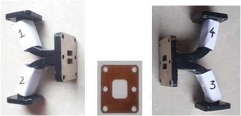
Based on theory, for the analysis of co-channel interference, MATLAB codes have been written, and simulation has been done using CST microwave studio. For validation of theory, measurement has been carried out. During the measurement two-channel E-plane bends are joined together with a common flange and a copper plate, as shown in Fig. 3. Scattering parameters data obtained from MCMT analysis for E-plane WR-42 two channels waveguide joint at K-band has been compared with CST microwave studio simulated data as well as with measured data.
Image of two-channel E-plane waveguide bends and a copper plate.

In the beginning, measurement of the magnitude of S-parameter for frequency range 20.5–22.5 GHz without metallic plate has been done by VNA (Agilent Technologies, E8363B) which is shown in Fig. 4. Further, different dimensions of the gap have been taken, shown in Table 1.
Graph of measured S-parameters for E-plane WR-42 waveguide two-channel joints for K-band without a gap.

Different dimensions of the gap for measurement.

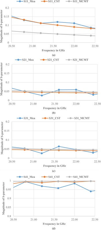
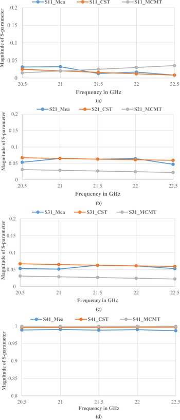
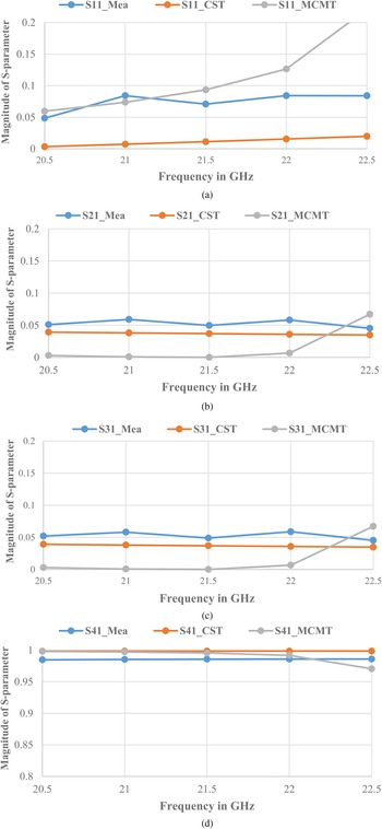
One after another measurement of the magnitude of S 11, S 21, S 31 and S 41 for K-band E-plane WR-42 waveguide two-channel joints with different gap sizes has been done as shown in Figs5–7. From Figs 5(a) to 5(d), it depicts that the maximum value of coupling of power is 0.33% at 21.6 GHz while in Figs6(a) to 6(d) it is 0.36% over the frequency range 21 to 22GHz. From Figs 7(a) to 7(d), It shows that the highest value of coupling is 0.25% at 22 GHz.
Comparison of scattering parameters (a) S 11, (b) S 21, (c) S 31 and (d) S 41 of MCMT, CST microwave studio simulated data and measured data for E-plane WR-42 waveguide two-channel joints for K-band with a gap of 2t = 0.3 mm, d = 0.6 mm and d1 = 6.18 mm.

Comparison of scattering parameters (a) S 11, (b) S 21, (c) S 31 and (d) S 41 of MCMT, CST microwave studio simulated data and measured data for E-plane WR-42 waveguide two-channel joints for K-band with a gap of 2t = 0.5 mm, d = 0.166 mm and d1 = 2.182 mm.

Comparison of scattering parameters (a) S 11, (b) S 21, (c) S 31 and (d) S 41 of MCMT, CST microwave studio simulated data and measured data for E-plane WR-42 waveguide two-channel joints for K-band with a gap of 2t = 0.3 mm, d = 0.66 mm and d1 = 3.184 mm.

Conclusion
Different dimensions of the gap have been taken to analyze the co-channel interference. The comparison of scattering parameters shows excellent matching of CST simulated data, measured data and MCMT data. It has been seen that the maximum value of coupling of power to neighboring port is 0.36% over the frequency range 21 to 22 GHz when the gap size is 2t = 0.5 mm, d = 0.166 mm and d1 = 2.182 mm. MCMT technique can be used for other higher frequency bands. This analysis is helpful to give insight for multiple input and multiple output applications.
Acknowledgements
The support provided by Medicaps University is gratefully acknowledged.
 Neelam Sharma obtained her diploma in 2001 and B.E. in 2004 from RGPV University. She also received her M.Tech in 2011 from DAVV University. Currently, she is pursuing Ph.D. from Medicaps University, Indore, India.
 Dr. Debendra Kumar Panda obtained his ME in 2003 from the Indian Institute of Engineering Science and Technology and Ph.D. (electronics and electrical communication engineering) in 2010 from the Indian Institute of Technology Kharagpur, West Bengal, India. He is currently working as pro-vice chancellor in Medicaps University, Indore, India.