Introduction
Ultra-wide band (UWB) technology has received more attention due to high data rate, low power, and low cost. Federal communication commission allowed the range of UWB for the first time in 2002 from 3.1 to 10.6 GHz [1]. Various conventional designs have been proposed for UWB application [Reference Khan, Khattak, Witjaksono, Barki, Ullah, Khan and Lee2–Reference Khan, Khan, Ahmad and Saleem7]; however, there is a problem of multipath fading associated with UWB technology in dense medium. To overcome multipath fading various, multiple-input and multiple-output (MIMO) antenna designs with a decoupling stub have been proposed [Reference Mathur and Dwari8–Reference Khan, Khattak, Rahman, Qazi, Telba and Sebak26].
A semi-hexagonal-shaped prototype UWB-MIMO antenna with a decoupling stub is presented; the size of the antenna is 20 × 34 mm2, the operating frequency range is 3 − 11 GHz with an 8 GHz impedance bandwidth. Furthermore, a technique of circular ring resonator is used for the surface suppression and the improvement of the port isolation; mutual coupling of less than −20 dB in most of the achieved bands is also noted [Reference Mathur and Dwari8]. MIMO-UWB design having a rectangular-shaped radiating element for wideband applications of size 21 × 34 mm2 with a better port isolation of 22 dB and an average radiation efficiency of 62% is proposed in [Reference Tiwari, Singh and Kanaujia9]. Moreover, the antenna operated in the UWB range from 3.52 to 9.89 GHz with an impedance bandwidth of 95%, and neutralization line technique for the minimization of mutual coupling is adopted. A modified rectangular-shaped radiating element having staircase lower end and U-shaped upper end, MIMO antenna with dimensions 26 × 31 mm2 for UWB applications having a comb-line stub in ground plane with a mutual coupling of lower than −25 dB between the two ports and operating over the frequency range from 3.1 to 10.6 GHz with an impedance bandwidth of 7.5 GHz is investigated in [Reference Malekpour and Honarvar10]. An MIMO antenna with a T-shaped wavy strip grounded stub for super wideband applications having identical semi-circular radiating elements with an overall size of 40 × 47 mm2 having an impedance bandwidth of 187% (1.3–40 GHz) with an isolation of greater than 20 dB and efficiency is greater than 80% is presented in [Reference Ullah, Rahman, Cao, Khan and Ullah11].
Quarter-circular-shared radiator and square ground of size 26 × 26 mm2 fed with an asymmetrical coplanar strip (ACS) MIMO antenna for UWB applications having an acceptable port isolation of greater than 15 dB and operating over the frequency range from 3.1 to 10.6 GHz with an impedance bandwidth of 7.5 GHz is proposed in [Reference Zhang, Zhang, Tian and Luo12]. In addition, the frequency range is broadened and mutual coupling between the ports is minimized by etching an I-shaped slot in the shared radiator, adding a rectangular back patch as well as with the help of grounded stub. A four-element circular geometry MIMO antenna of size 40 × 40 mm2 with a port isolation of greater than 20 dB over the achieved UWB band from 3.1 to 11 GHz approximately having almost constant 3.28 dBi of average gain is investigated. Two radiating elements are printed on one side with a rectangular-slotted partial ground and two on back side and they are arranged in such a manner that elements on both sides are perpendicular to each other. There is a decoupling stub between the two elements for port isolation on both sides of the substrate [Reference Ali and Ibrahim13]. In [Reference Toktas and Akdagli14], an orthogonally arranged planar radiator with circularly trimmed lower end and triangularly trimmed upper edge ground microstrip-fed antenna of size 26 × 55 mm2 for MIMO-UWB applications with an impedance bandwidth of 9.4 GHz (3.1 − 12.3 GHz) bearing less than −20 dB of mutual coupling is proposed. Also, quad radiating elements MIMO arrangement is studied and their results have been investigated.
Two port rectangular-shaped radiators and T-shaped stub are introduced to enhance isolation; the size of the MIMO antenna is 18 × 36 mm2, isolation is greater than 20 dB, and envelope correlation coefficient (ECC) is less than 0.05 [Reference Khan and Khattak15]. In [Reference Wu, Ding, Zhang, Li, Wu and Wang16], the authors proposed two differently shaped antennas for UWB applications; the size of the antenna is 25 × 35 mm2, bandwidth is 7.5 GHz ranging from 3.1 to 10.6 GHz, and ECC is less 0.005. In [Reference Zhao, Zhang, Wang and Liang17], half circular-shaped radiators with I-shaped stub are proposed; isolation is greater than 15 dB, the size of the presented antenna is 30 × 36 mm2, and bandwidth is 7.5 GHz ranging from 3.1 to 10.6 GHz. In [Reference Ghimire, Choi and Choi18], the authors presented a very large size MIMO antenna with parasitic elements to enhance isolation; the size of the antenna is 65 × 65 mm2, the isolation is greater than 15 dB, and ECC is less than 0.007. In [Reference Liu, Wang and Qin19], uniplanar MIMO-UWB design having two circular radiating elements fed with a modified orthogonal ACS with a diagonally rectangular stub in between the radiators of size 28.5 × 28.5 mm2, operating over the frequency range from 2.66 to 11.08 GHz is proposed. A quad-element hexagon-molecule-shaped UWB fractal MIMO antenna having a half-circular partial ground of size 40 × 40 mm2 with an inter-port isolation greater than 20 dB and operating over the frequency range from 2.4 to 10.6 GHz having an impedance bandwidth of 9 GHz is investigated in [Reference Rajkumar, Amala and Selvan20]. A quarter-wave-fed, bi-radiating elements E-slot semi-circular MIMO antenna of size 42 × 30 mm2 for UWB applications is proposed in [Reference Bhanumathi and Sivaranjani21], having an inter-port isolation of greater than 20 dB and operating over the frequency range from 3.04 to 10.87 GHz. A narrow rectangular slot is introduced into ground for better port isolation and efficiency of greater than 76% is also noted. A bi-elements circular monopole MIMO UWB antenna of 24 × 33 mm2 size covering UWB from 2.75 to 11 GHz with a mutual coupling of less than −20 dB, having an inverted T-shaped slotted modified protruded ground is investigated in [Reference Li, Liu, Wang and Yin22]. And a quad-element orthogonally arranged array configuration of size 44 × 44 mm2 is also proposed in the same paper. A modified protruded grounded with a central rectangular strip, 50-ohm bend microstrip feed planar monopole rectangular radiating elements MIMO-UWB antenna of size 30.1 × 20.5 mm2 with better inter-port isolation of greater than 25 dB having an impedance bandwidth of 9.7 GHz (3.1 − 10.6 GHz) is presented in [Reference Babashah, Hassani and Mohammad-Ali-Nezhad23]. The authors proposed OWL-shaped MIMO antenna with a protruded ground to enhance isolation; the size of the antenna is 26 × 31 mm2, isolation is greater than 20 dB, and bandwidth is 8.02 GHz in the range from 3.1 to 11.12 GHz [Reference Mchbal, Amar Touhami, Elftouh and Dkiouak24]. In [Reference Kiem, Phuong and Chien25], four-port MIMO antennas are presented with an overall size of 60 × 60 mm2; isolation is greater than 15 dB and bandwidth is 7.95 GHz in the range from 2.73 to 10.68 GHz. A circular-shaped UWB-MIMO antenna with an elliptical-T-shaped decoupling stub is proposed in [Reference Khan, Khattak, Rahman, Qazi, Telba and Sebak26]. Details of literature and proposed design are summarized in Table 1.
Comparison between the proposed design and literature

In this paper, a coplanar waveguide (CPW)-fed UWB-MIMO antenna with the dimensions of 18 × 22 × 1.6 mm2 is presented. The voltage standing wave ratio (VSWR) is less than 2 between 2.8 and 13 GHz with an impedance bandwidth of 10.2 GHz. The proposed UWB-MIMO antenna has good isolation, ECC, diversity gain (DG), peak gain, and multiplexing efficiency as compared to the literature cited.
Antenna design and configuration
Antenna design
The geometry of the proposed MIMO antenna is depicted in Fig. 1, and similarly |S| parameters are depicted in Fig. 2. The proposed antenna is printed on an FR4 dielectric material with a thickness of 1.6 mm. The antenna is fed with CPW feeding, in which the ground plane and radiation elements are printed on the same front side. The proposed MIMO antenna comprises dielectric substrate, ground plane, and two similar structure radiating elements. Radiating element consists of simple circular and rectangular patch; rectangular patch is added to circular patch to adjust the lower cutoff frequency of UWB by increasing the length of the radiating element. The overall dimension of the MIMO design is 18 mm × 22 mm. The radius of circular patch is 4 mm. The dimension of the rectangular patch is 2.55 mm × 5.40 mm and the gap between ground plane and feed line is 0.4 mm. The distance between the centers of the two radiating elements is 15.2 mm and the dimension of the feed line is 5.6 mm × 1.2 mm. The performance of the UWB antenna is greatly dependent on size of the ground. Moreover, the extended ground is applied to allow a longer current path to achieve a lower cutoff frequency equally to reduce the oversize of the antenna. This is because the extended ground can also be considered as a reflector to separate the radiation patterns of the two radiators, which helps to reduce the mutual coupling between the two ports. The length and width of top of the castle-shaped stub is 18 and 1 mm respectively; various other parameters are summarized in Table 2.
Design geometry of CPW-fed MIMO antenna for UWB application.

Simulated |S| parameters of CPW-fed MIMO antenna for UWB application.

Parameters of the proposed CPW-fed MIMO antenna

Decoupling stub
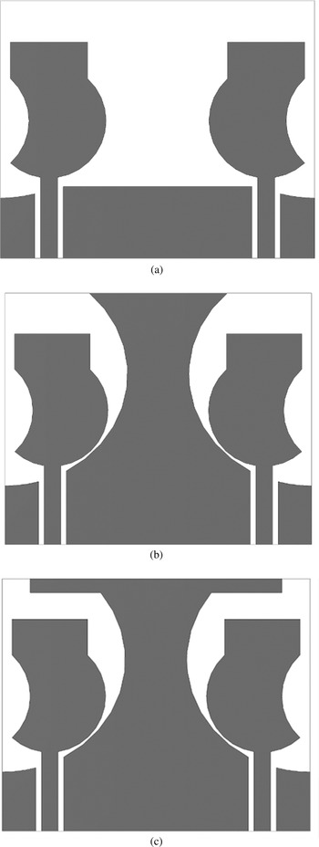
Mutual coupling is the main issue in MIMO systems; decoupling stub is used to increase isolation and reduce mutual coupling. Various decoupling stubs are used to enhance isolation [Reference Mathur and Dwari8–Reference Khan, Khattak, Rahman, Qazi, Telba and Sebak26]. In this design, a castle-shaped decoupling stub is introduced to enhance isolation. The structure of the decoupling stub is evaluated and optimized for various values; the structure of evaluation steps and their |S| parameters are depicted in Figs 3 and 4, respectively. The decoupling stub involves three steps: Ant1 is without a decoupling stub, Ant2 is with a decoupling stub but without a T-shaped strip, and Ant3 is the proposed design. In Ant1, the mutual coupling is maximum and isolation is minimum due to the absence of decoupling stub; in Ant2, the mutual coupling is reduced due to change in current distribution by using decoupling stub, similarly a T-shaped strip is added to the decoupling stub to enhance isolation, which is justified from Fig. 4.
Design evaluation steps of decoupling stub: (a) MIMO Ant1, (b) MIMO Ant2, and (c) MIMO Ant3.

|S| parameters of evaluation steps of decoupling stub in CPW-fed MIMO antenna for UWB application.

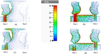
Current distribution (port-1 is exited) at various frequencies of the proposed CPW-fed MIMO antenna with and without a decoupling stub is depicted in Fig. 5. In the current distribution without a decoupling stub, most of the current is concentrated on port-2 as observed in Fig. 5. In the current distribution with a decoupling stub, most of the current is concentrated on left side of the decoupling stub and port-2 is isolated from port-1 due to change in the direction of current.
Surface current distribution of in CPW-fed MIMO antenna: (a) 3.5 GHz with a decoupling stub, (b) 3.5 GHz without a decoupling stub, (c) 5.5 GHz with a decoupling stub, and (d) 5.5 GHz without a decoupling stub.

Parametric analysis
The parametric analysis was accomplished by observing the variations in reflection coefficients and isolations with the variation in different parts of the antenna such as radius of the radiating patch (r), width of the T-shaped decoupling stub (lt), and height of ground patch (lg). The ground plane and decoupling stub have two main functions: providing impedance matching and reduce mutual coupling.
The parametric analysis of radiating patch is depicted in Fig. 6. The isolations is nearly the same for all values of “r”, but reflection coefficient is drastically affected if r is increased or decreased by 1 mm. The reflection coefficient is poor between 4 and 6 GHz for r = 3 mm and poor reflection coefficient between 6 and 10 GHz for r = 5 mm. The parametric analysis of ground plane is depicted in Fig. 7. The reflection coefficient is relatively better in the entire UWB for l g = 4.2 mm. The mismatch losses have been increased in the 4–5 GHz frequency band and above 7 GHz for l g = 3.2 mm and similarly mismatch losses occurred in the entire UWB for l g = 5.2 mm. The isolation is poor in lower frequencies and relatively better beyond 6 GHz for both smaller and larger values of l g. When the width of T-shaped decoupling stub (lt) is varied from 14 to 22 mm, variations in the reflection coefficients and isolations are observed, as shown in Fig. 8. A relatively better response in the entire UWB band is observed for lt = 18 mm. The impedance matching is poor beyond 8 GHz and similarly isolations are degraded between 3 and 5 GHz and beyond 9 GHz for both smaller and larger values of lt. The effect of a decoupling structure on the antenna gain is shown in Fig. 9. The antenna gain is relatively better for lt = 18 mm.
Parametric analysis by varying the length and width of radiating patch (r).

Parametric analysis by varying the height of ground patch (lg).

Parametric analysis by varying the width of T-shaped decoupling stub (lt).

Analysis of peak gain by varying the width of T-shaped decoupling stub (lt).

Results and discussion
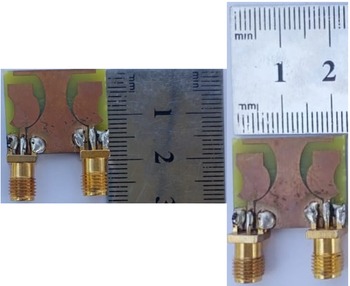
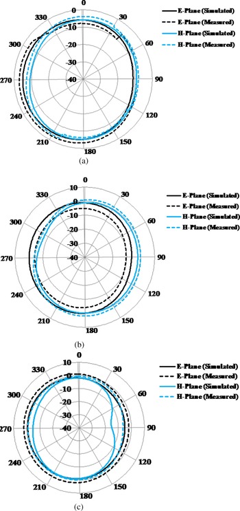
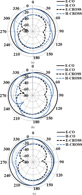
The proposed MIMO-UWB antenna is printed on an FR4 substrate and simulated in CST microwave studio. The prototype of the CPW-fed MIMO-UWB antenna is depicted in Fig. 10. The measured and simulated |S| parameters are compared in Fig. 11. The |S 11| of the presented MIMO antenna is less than −10 dB between 2.8 and 13 GHz with an impedance bandwidth of 10.2 GHz and isolation is greater than 20 dB, a small change is noticed at higher frequencies in both |S 11|/|S 22| and |S 12|/|S 21|. Simulated and measured radiation patterns in both E-plane (ϕ = 0) and H-plane (ϕ = 90) are depicted in Fig. 12; the radiation pattern in both E-plane (ϕ = 0) and H-plane (ϕ = 90) are stable and nearly omni-directional. Figures 11 and 12 show good agreement between simulated and measured results. Co- and cross-polar components in the E-plane and H-plane at various frequencies are also depicted in Fig. 13; the values of cross-polarization is less than those of co-polarization.
Prototype of CPW-fed MIMO antenna for UWB application.

Measured and simulated S-parameters of CPW-fed MIMO antenna for UWB application.

Measured and simulated E-plane and H-plane of CPW-fed MIMO antenna for UWB application: (a) 3.5 GHz, (b) 5.5 GHz, and (c) 8.2 GHz.

Co- and cross-polar components in E-plane and H-plane of CPW-fed MIMO antenna for UWB application: (a) 3.5 GHz, (b) 5.5 GHz, and (c) 8.2 GHz.

ECC and DG are two significant parameters in MIMO antennas. ECC shows that how the multiple antennas are correlated; for ideal antennas, ECC is equal to zero and for practical antennas ECC is less 0.5. ECC and DG are depicted in Fig. 14. In the proposed design, ECC is less than 0.007 and DG is greater than 9.97 dB. ECC and DG are calculated using the below formulas [Reference Blanch, Romeu and Corbella27]:


ECC and DG of proposed of CPW-fed MIMO antenna for UWB application.

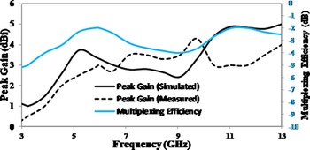
Multiplexing efficiency is another parameter for the evaluation of MIMO antennas. It is normal to consider radiation efficiency, but it also include imbalance in efficiency and correlation. Multiplexing efficiency and peak gain are depicted in Fig. 15. Measured and simulated peak gains are varying between 0 and 5 dBi and multiplexing efficiency is varying between −5 and −2 dB. The group delay of the proposed CPW-fed MIMO-UWB antenna is depicted in Fig. 15; group delay characterizes the degree of distortion in the UWB-MIMO antenna. A uniform and stable group delay is the need of UWB systems. The group delay of the proposed antenna is stable and uniform, and has less variation in the entire UWB range. It can be concluded from Fig. 16 that the signal of the UWB system was not distorted between the transmitting and the receiving antennas. Measured and simulated results show significant agreement, and the proposed antenna can be used for various wireless communication applications.
Multiplexing efficiency and peak gain of CPW-fed MIMO antenna for UWB application.

Group delay of CPW-fed MIMO antenna for UWB application.

Conclusion
This research article proposed a CPW-fed MIMO antenna with very small size for UWB application. The proposed antenna is simulated in CST studio and fabricated practically to validate the results. The impedance bandwidth is 10.2 GHz from 2.8 to 13 GHz. The ECC is less than 0.007, DG is greater than 9.97 dB, and peak gain is 5 dBi. The proposed antenna has good isolation, ECC, DG, peak gain, and multiplexing efficiency. Measured and simulated results show that the proposed antenna is a suitable candidate and can be used for various MIMO-UWB wireless communication applications.
Acknowledgement
This study was supported by the Deanship of Scientific Research at Prince Sattam bin Abdulaziz University, Saudi Arabia.
 M. Irfan Khattak received the B.Sc. degree in electrical engineering from the University of Engineering and Technology, Peshawar, in 2004, and Ph.D. from Loughborough University, UK, in 2010. On completion of Ph.D., he was appointed as the chairman, Electrical Engineering Department, UET Bannu Campus for five years and was in charge of the academic and research activities. Later in 2016, he was appointed as the campus coordinator of UET Kohat Campus and took the administrative control of the campus. He is currently working as an associate professor with the Department of Electrical Engineering, University of Engineering and Technology. He is also the head of a research group, Microwave and Antenna Research Group, where he supervises postgraduate students working on latest trends in antenna technology like 5G and graphene nano-antennas for terahertz, optoelectronic and plasmonic applications and so on. His research interests involve antenna design, on-body communications, anechoic chamber characterization, and speech processing and speech enhancement. Besides his research activities he is a certified OBE expert with Pakistan Engineering Council for organizing OBA-based accreditation visits.
 Muhammad Irshad Khan received the B.Sc. (Hons.) degree in electrical electronic engineering from the Comsats Institute of Information Technology Abbottabad, Pakistan and the M.Sc. degree in electrical engineering from the Capital University of Science and Technology, Islamabad, Pakistan in 2016. He is currently pursuing Ph.D. degree in electrical engineering under the supervision of Dr. M. I. Khattak from the University of Engineering and Technology, Peshawar, Pakistan. His research interests include microwave and RF circuit design, UWB antenna design and analysis, MIMO antennas, beam steering antennas and reconfigurable antenna design.
 Muhammad Anab is working as laboratory engineer in the Department of Electrical Engineering in University of Engineering and Technology Peshawar. He received his B.Sc. (Hons.) degree in electrical engineering from University of Engineering and Technology Peshawar in 2016 and M.Sc. degree in electrical engineering from the same University in 2019. He is also a member of ìMicrowave and Antenna Research Groupî supervised by Dr. Muhammad Irfan Khattak and his research interests include dielectric resonator antenna (DRA) design and analysis for 5G Applications, 5G Microstrip patch Antenna design and graphene-based terahertz antennas.
 Amjad Ullah received the B.Sc. degree in electrical engineering from the University of Engineering and Technology, Peshawar, in 1992, the M.Sc. degree in computer & communication security from the George Washington University, Washington, DC, USA, and Ph.D. degree from the University of Engineering and Technology, Peshawar, in 2010. He is currently working as professor in the Department of Electrical Engineering, University of Engineering and Technology. His research interests include microwave and RF circuit design, beam steering antennas, digital communication, channel estimation, and computer networks.
 Muath Al-Hasan received his B.A.Sc. degree in electrical engineering from the Jordan University of Science and Technology, Jordan, in 2005, the M.A.Sc in wireless communications from Yarmouk University, Jordan in 2008, and Ph.D. degree in telecommunication engineering from Institut National de la Recherche Scientifique (INRS), Université du Québec, Canada, 2015. From 2013 to 2014, he was with Planets Inc., California, USA. In May 2015, he joined Concordia University, Canada as a postdoctoral fellow. He is currently an assistant professor with Al Ain University, United Arab Emirates. His current research interests include antenna design at millimeter-wave and terahertz, channel measurements in multiple-input and multiple-output (MIMO) systems, and machine learning and artificial intelligence in antenna design.
 Jamel Nebhen received M.Sc. in microelectronics from the National Engineering School of Sfax, Tunisia in 2007, and Ph.D. from the Aix-Marseille University, France, in 2012, all in microelectronics. From 2012 to 2018, he worked as a postdoctoral researcher in France in LIRMM-Lab Montpellier, IM2NP-Lab Marseille, ISEP Paris, LE2I-Lab Dijon, Lab-Sticc Telecom Bretagne Brest, and IEMN-Lab Lille. Since 2019, he joined the Prince Sattam bin Abdulaziz University in Alkharj, Saudi Arabia, as an assistant professor. His research interests are mainly in the design of analog and RF integrated circuits, IoT, biomedical circuit, and sensors instrumentation.