


1. INTRODUCTION
Many maritime situational awareness applications, including fishing monitoring, search and rescue, environmental monitoring, anti-piracy operations and military reconnaissance rely on ship surveillance techniques. Space-borne Synthetic Aperture Radar (SAR) and Automatic Identification System (AIS) can work well together, and integrated surveillance systems have larger potential, and demand further investigation (Brusch et al., Reference Brusch, Lehner, Fritz, Schwarz, Lehner and Hamidi2011). State-of-the-art data processing algorithms do not always achieve satisfactory performance in high-density shipping or high sea-state conditions.
Data association based on the position feature is generally feasible. However, in the complex conditions mentioned above, performance is not favourable, prompting the investigation of multi-feature-based association. Ship identification and tracking by the integration of space-borne SAR and AIS is feasible. However, not all ships are equipped with or operate AIS, and ships not reported by AIS may be detected by SAR, meanwhile, ships not detected by SAR might be reported by AIS, so it is necessary to investigate the detailed cooperative process. Multi-source data fusion offers promise for the future, and the fusion strategy should be studied further.
This paper aims to investigate topics including improved data association methods in Section 2, ship identification, ship tracking, and multi-sensor information fusion strategy in Section 3. The discussion is presented in Section 4, and Section 5 concludes the paper with remarks on future work.
2. IMPROVED DATA ASSOCIATION
Current state-of-the-art data association methods mainly include three phases: AIS position projection, AIS position prediction, and searching and matching. For AIS position projection, there exist many challenges for the prediction of ship motion especially for non-linear or more complex motions. Even for stationary ships, which are moored or anchored, ship position is a random-walk dominated by the “noise” (sea surface motion and wind factors). Affected by wind and waves, ships have roll, pitch and yaw motions. The aspect angle varies strongly, especially under high-sea-state conditions. All of these lead to difficulties in prediction of ship motion. AIS position prediction is actually the reverse compensation for Doppler shift in azimuth. To derive more accurate azimuth displacement, the projected Course over Ground (CoG) and Speed over Ground (SoG) need to be accurately estimated. The searching and matching method adopts Nearest Neighbour re-sampling, which might not be feasible under high-density shipping or high sea-state conditions. By considering multiple features in the data association algorithm, the accuracy may be improved. This section firstly researches an improved data association method based on the position feature, and then presents the multi-features-based association method.
2.1. Improved Multi-Target Data Association Based on the Position Feature
This section presents the new ideas from three aspects: AIS Position Projection, AIS Position Prediction, and Searching and Matching.
2.1.1. AIS Position Projection
AIS position projection aims to derive the ship position at the labelled time (SAR image acquisition time) using AIS fixes. The task is to predict the ship's track based on an analysis of its motion.
The vast majority of ships use course-keeping autopilots, and only the most modern use track-keeping autopilots. Course-keeping holds the heading constant, which is significant for anti-collision, tracking and positioning. However, many factors affect the ship motion and lead to deviations from course. For the autopilot itself, although many valid controlling algorithms (e.g., neural network, genetic algorithm) have already been developed to improve the controlling ability for course-keeping and course-changing, course deviation is unavoidable, and will be exacerbated by the environmental conditions (mainly the sea and wind factors).
Coordinate transformation is an important problem to be considered before the AIS position projection. The position information from an AIS report comes from the Global Position System (GPS) or Differential GPS (DGPS), which adopts the World Geodetic System 1984 (WGS84) coordinate system. In the track-keeping case, ship track described by a great circle path between two points under geodetic coordinates is not of constant course, and it brings difficulty in the calculation of travelling distance in predicting the position. Mercator projection is a kind of equiangular projection, in which the straight lines are of constant course, called loxodromes or rhumb lines, over the Earth's surface (Vachon et al., Reference Vachon, English and Wolfe2007). After the AIS position coordinates transformation from WGS84 to the Mercator projection, the course-keeping track is a straight line, and helpful to the prediction. Meanwhile, the Mercator projection is also applied to the space-borne SAR image, and it would benefit data association of space-borne SAR and AIS.
After the coordinate transformation, the prediction becomes much easier. Without considering the complex stochastic factors, when the course keeps constant, the ship track is obviously a straight line, and when it comes to the course-changing case, the track will be presented as an arc (not fold line). The ship cannot turn to the desired course directly due to its intrinsic characteristics and needs time to alter from the old course to the new. However, the environmental influences are unavoidable, so the tracks would not be the ideal ones illustrated above, but they are similar to the ideal with some errors. Due to the difficulties in estimating these unforeseen errors (e.g., the sea influence), they are usually predicted approximately using the ideal models.
State-of-the-art prediction methods based on dead reckoning use the zero-order, first order and second order derivative polynomials models:
 $$s = s_0 $$
 $$s = s_0 + v\Delta t$$
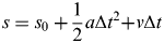 $$s = s_0 + \displaystyle{1 \over 2}a\Delta t^2 {\rm +} v\Delta t$$
where s 0 and s are the initial and final position respectively, v is the initial speed, a is the acceleration speed, and  $\Delta t$ is the time interval.
They are commonly used to represent ship anchoring, straight line motion with uniform speed and uniform acceleration speed respectively, considering only the ship itself without environmental factors.
The higher-order (greater than three) prediction model may improve the accuracy for ship accelerated or decelerated motion (Qu et al., Reference Qu, Gao and Zhu2008), which uses the Taylor Formula below:
 $$\eqalign{f\,(x) = f\,(x_0 ) + f^{\prime} (x_0 )(x - x_0 ) + \displaystyle{1 \over 2}f^{''} (x_0 )(x - x_0 )^2 + \cdots + \displaystyle{1 \over {n!}}f^n (x_0 )(x - x_0 )^n + R_n }$$
where  $$R_n = \displaystyle{1 \over {(n + 1)!}}f^{(n + 1)} (\xi )(x - x_0 )^{n{\rm +} 1} $, ξ∈(x 0,x).
Theoretically using high-order derivative polynomials could improve the accuracy, but this considers the ship's navigational status without considering the sea factors. Meanwhile, higher derivatives would increase the risk of inaccurate prediction caused by non-valid prediction for acceleration, and it might be safer to remain with first-order or second-order prediction (Jouni et al., Reference Jouni, Timo and Harri2002).
The AIS estimations of CoG and SoG can be used to help the prediction of ship motion. Dead reckoning (DR) also estimates CoG and SoG, but is usually based on a single AIS snapshot (normally the pre-image snapshot, when not available the post-image one is used and reverse dead reckoning is implemented). This assumes that the SoG is constant or varies uniformly, and the CoG is constant. However, real conditions may not all be like that. To achieve higher accuracy, they could be estimated by sequential AIS snapshots (before, after or around the SAR image acquisition time). As ship motion has continuity and heredity, and the motion pattern within a certain short time span has little or no change, using the sequential AIS snapshots before or after the labelled time to estimate SoG and CoG is practical. Theoretically, using the sequential AIS snapshots around the labelled time to estimate is more accurate. They are usually estimated based on the two nearest AIS snapshots (pre-image and post-image). When the pair-wise AIS snapshots are used for estimation, there are four conditions to be dealt with:
• CoG equal, SoG equal. It is considered as a linear movement with uniform SoG.
• CoG equal, SoG non-equal. It is considered as a linear movement with uniform acceleration or deceleration speed.
• CoG non-equal, SoG equal. It is considered as an arc movement with uniform SoG, and a non-zero constant Rate of Turn (ROT).
• CoG non-equal, SoG non-equal. It is considered as an arc movement with uniform acceleration or deceleration speed, and a non-zero constant Rate of Turn (ROT).
For simplicity, the variables are all set uniform or constant for the non-equal conditions, and then, the projected position can be easily derived.
To improve the accuracy, Gray Prediction would probably be another good choice. Gray Prediction has satisfactory prediction performance under the condition that there are small samples and poor information, and is characterized by simplicity and practicability (Zou et al., Reference Zou, Mou and Yi2012). Gray Prediction based on the observational data sequence (AIS snapshots) emphasises deriving the intrinsic regularity of the sequence.
Both ship movement itself and the sea influence affect ship position. Under certain sea conditions, the sea influence on position could be considered with some regularity. However, the DR method does not consider the sea influence on position, and only uses the kinematics formula to predict. Compared to DR, the Gray Prediction model enhances the intrinsic regularity of the AIS fixes sequence, and could possibly improve the accuracy of position prediction by considering the influences caused by the environment.
We present here a Multi-variable Gray Reciprocal-accumulation Model (MGRM (1, N)) based on multiple variables and reciprocal accumulated generating operation, which is made up of two models-MGM (1, N) (Multi-variable Gray Model) and GRM (1, N) (Gray Reciprocal-accumulation Model). Ship track relates to the aspect angle and speed, so the MGM (1, N) model can be adopted to resolve the problem that ship motion is affected by multiple variables. The GRM (1, N) model is also characterized by high accuracy and better practicality, and both can be used in non-equal interval and equal interval time series (Zou et al., Reference Zou, Mou and Yi2012). Considering that the AIS-report interval may either change or not depending on the SoG, the GRM (1, N) model is used to improve the accuracy. As the importance of the position information, further from the one to be predicted, is decreasing in the time axis, so the number of AIS snapshots chosen to predict should be limited. Additionally, the input of the MGRM model should be the monotonic decreasing sequences. The sequences should be made up of both pre-image and post-image AIS snapshots to improve the accuracy. Ship's track always remains monotonic within the short term, so a certain number of AIS snapshots around SAR image acquisition time, which satisfy the monotonic decreasing trend after self-adaptable translation and rotation of the coordinate system, can be selected. Supposing that the sequences of ship position coordinates are set as:
 $$X_x^{(0')} = \left\{ {x_x^{(0')} (t_1 ),x_x^{(0')} (t_2 ),x_x^{(0')} (t_3 ), \cdots, x_x^{(0')} (t_m )} \right\}$$
 $$X_y^{(0')} = \left\{ {x_y^{(0')} (t_1 ),x_y^{(0')} (t_2 ),x_y^{(0')} (t_3 ), \cdots, x_y^{(0')} (t_m )} \right\}$
Then the reciprocal sequences of  $X_x^{(0')} $ and
 $X_y^{(0')} $ are:
 $$X_x^{(0)} = \left\{ {x_x^{(0)} (t_1 ),x_x^{(0)} (t_2 ),x_x^{(0)} (t_3 ), \cdots, x_x^{(0)} (t_m )} \right\}$$
 $$X_y^{(0)} = \left\{ {x_y^{(0)} (t_1 ),x_y^{(0)} (t_2 ),x_y^{(0)} (t_3 ), \cdots, x_y^{(0)} (t_m )} \right\}$$
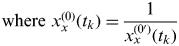 ${\rm where}\ x_x^{(0)} (t_k ) = \displaystyle{1 \over {x_x^{(0')} (t_k )}}$,
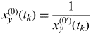 $x_y^{(0)} (t_k ) = \displaystyle{1 \over {x_y^{(0')} (t_k )}}$, k=1,2,…m.
X x(1) and X y(1) are respectively referred to as the first order reciprocal Accumulated Generating Operation (AGO) of sequence X x(0) and X y(0). The definitions of X x(1) and X y(1) are:
 $$X_x^{(1)} = \left\{ {x_x^{(1)} (t_1 ),x_x^{(1)} (t_2 ),x_x^{(1)} (t_3 ), \cdots, x_x^{(1)} (t_m )} \right\}$$
 $$X_y^{(1)} = \left\{ {x_y^{(1)} (t_1 ),x_y^{(1)} (t_2 ),x_y^{(1)} (t_3 ), \cdots, x_y^{(1)} (t_m )} \right\}$$
where
 $$x_x^{(1)} (t_k ) = \left\{ {\matrix{ {x_x^{(0)} (t_1 )} & {k = 1} \cr {x_x^{(0)} (t_1 ) + \sum\limits_{i = 1}^k {x_x^{(1)} (t_i )(t_i - t_{i - 1} )}} & {k = 2,3, \cdots m}, \cr}} \right.$$
 $${\rm} x_y^{(1)} (t_k ) = \left\{ {\matrix{ {x_y^{(0)} (t_1 )} & {k = 1} \cr {x_y^{(0)} (t_1 ) + \sum\limits_{i = 1}^k {x_y^{(1)} (t_i )(t_i - t_{i - 1} )}} & {k = 2,3, \cdots m} \cr}} \right.$$
The model's albino differential equations are:
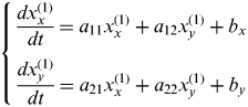 $$\left\{ {\matrix{ {\displaystyle{{dx_x^{(1)}} \over {dt}} = a_{11} x_x^{(1)} + a_{12} x_y^{(1)} + b_x} \cr {\displaystyle{{dx_y^{(1)}} \over {dt}} = a_{21} x_x^{(1)} + a_{22} x_y^{(1)} + b_y} \cr}} \right.$$
The background values are:
 $$z_p^{(1)} = \left\{ {z_p^{(1)} (t_2 ),z_p^{(1)} (t_3 ), \cdots, z_p^{(1)} (t_n )} \right\}$$
where  $z_p^{(1)} (t_n ){\rm =} 0.5(x_p^{(1)} (t_n ){+ x}_p^{(1)} (t_{n - 1} )), p = x,y$.
Set ā=[A,B]T, where 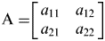 ${\rm A =} \left[ {\matrix{ {a_{11}} & {a_{12}} \cr {a_{21}} & {a_{22}} \cr}} \right]$ and
 $B = \left[ {\matrix{ {b_x} \cr {b_y} \cr}} \right]$, as the parameter of model MGRM (1, N), so the least square can be estimated as:
 $$\overline a = (S^T S)^{ - 1} S^T T$$
where
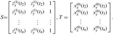 $$S{\rm =} \left[ {\matrix{ {z_x^{(1)} (t_2 )} & {z_y^{(1)} (t_2 )} & 1 \cr {z_x^{(1)} (t_3 )} & {z_y^{(1)} (t_3 )} & 1 \cr \vdots & \vdots & \vdots \cr {z_x^{(1)} (t_n )} & {z_y^{(1)} (t_n )} & 1 \cr}} \right],T = \left[ {\matrix{ {x_x^{(0)} (t_2 )} & {x_y^{(0)} (t_2 )} \cr {x_x^{(0)} (t_3 )} & {x_y^{(0)} (t_3 )} \cr \vdots & \vdots \cr {x_x^{(0)} (t_n )} & {x_y^{(0)} (t_n )} \cr}} \right].$
So the time response of the differential Equation is:
 $$\overline X ^{(1)} (t_k ) = \left( {X^{(0)} (t_1 ) - A^{ - 1} B} \right)e^{ - A(t_k - t_1 )} + A^{ - 1} B$$
Additionally, the combination of the DR-based method and Gray Prediction may also be a better choice to improve the accuracy of prediction effectively.
2.1.2. AIS Position Prediction
The Azimuth displacement of the SAR image caused by the Doppler shift should also be considered. As mentioned above, to compensate AIS-projected position for the reverse Doppler shift is widely used, and the projected SoG and CoG can be derived from AIS snapshots more easily. However, to compensate the positions detected in the SAR image for the Doppler shift appears to be practical but more difficult, and the accuracy is difficult to guarantee. Ship speed parameters could be derived from ship wake, but this is limited because not all ships appearing in SAR images have wakes. Ship aspect angle can be estimated, but all techniques have disadvantages such as 180° blurring.
Furthermore, the accurate estimations of AIS-projected CoG and SoG should also be paid more attention, as the azimuth displacement could be expressed as (Vachon et al., Reference Vachon, English and Wolfe2007):
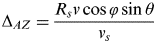 $$\Delta _{AZ} = \displaystyle{{R_s v\cos \varphi \sin \theta} \over {v_s}} $$
where R s is the spacecraft to target slant range, vs is the SAR platform velocity, θ is the target incidence angle, v is projected SoG, and φ is the difference between the range direction and the projected CoG. According to the formula above, accurate estimations of projected SoG and CoG lead to high accuracy of the azimuth displacement.
Small deviations in SoG and CoG could lead to relatively larger deviations. Using a single AIS fix to predict them accurately is not enough under some conditions (e.g., non-linear or turning). To derive more accurate projected SoG and CoG, using pair-wise AIS fixes around the labelled time for predictions is necessary. The CoG at the image acquisition time is always affected by the dynamic sea except in ideal conditions. The projected SoG is also affected by the sea wind or clutter, so the ideal projected speed should be a composite speed. Estimation error is unavoidable, and estimating projected SoG and CoG accurately under high sea-state conditions needs to be investigated further.
2.1.3. Searching and Matching
The state-of-the-art method for searching and matching uses Nearest Neighbour (NN) re-sampling, which is time-consuming for batch processing and possibly not valid for high-density shipping and other extreme conditions. Searching and matching based on spatial topological structure characteristics are possibly effective to solve these problems. The spatial topological structures of the target group detected by different sensors are similar, so Point Pattern Matching (PPM)-based methods can be applied to data association. False alarms and missing detections, together with the position differences, will always occur, which results in deviations among the spatial topological structures of the target group. Valid multi-target data association methods are needed to improve accuracy.
The positions extracted from SAR image and AIS reports are designated as two point sets. The centroids of ships detected in the SAR image constitute the template point set. AIS-predicted ship positions constitute the target point set. The two point sets to be matched have similar structure, but seldom satisfy the linear geometrical transformation. Relative Shape Context (RSC) (Zhao et al., Reference Zhao, Zhou, Sun and Li2010) can be used to solve the correspondence problem of point sets matching. This improves the robustness of shape context to outliers as well as noise and simultaneously keeps the invariance under geometric distortions. Additionally, there are always anomalistic distortions and these can be solved by non-rigid PPM methods adopting non-linear geometrical transformation models. For example, a probabilistic method called the Coherent Point Drift (CPD) algorithm (Myronenko and Song, Reference Myronenko and Song2010) is actually a maximum likelihood (ML) estimation problem. It fits the Gaussian Mixture model centroids (representing the template point set) to the observation data (the target point set) by maximizing the likelihood. Figure 1 shows an example of searching and matching between SAR ship contacts and corresponding AIS-predicted positions under the assumption that there are some ship targets (Numbers 10, 11 and 12) reported by AIS but not detected by SAR.
Comparisons among methods based on NN, RSC and CPD.

Figure 1(a) shows the two point sets. Figure 1(b) illustrates the matching result based on NN. In the red dashed boxes, SAR contact 2 is wrongly associated with AIS-predicted position 1, and SAR contact 7 is wrongly associated with outlier (AIS-predicted position) 10. Figures 1(c) and 1(d) show the associated results based on RSC and CPD. They are both associated correctly.
Furthermore, effective non-rigid point pattern matching methods could possibly be applied in the data association directly after data registration without position projection and prediction.
2.2. Multi-Target Data Association Based on Information Fusion of Multiple Features
To improve the validity and accuracy of data association, the multi-target data association based on information fusion of multiple features should be considered (Figure 2). This method integrates the associated measures of various features effectively. Linear (averaging, etc.) and non-linear processing (Dempster-Shafer Approach, Fuzzy Integration, etc.) are both available in the integration.
Flowchart of Multi-Target Data Association Based on Information Fusion of Multiple Features.
2.2.1. Averaging
Averaging includes average vote and weighted average (Wanas, Reference Wanas2003). Assume that the number of ships detected in a SAR image is M, and for an AIS report is N. Choose K(K⩾1) features to be associated. Set the ships detected in the SAR image as the targets to be associated. The output yielding the highest average value is chosen to be the correct associated target. For the rth ship in the SAR image, the output with the most confident measure can be expressed using the average vote as:
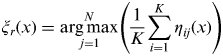 $$\xi _r (x) = \mathop {\arg \max} \limits_{\,j = 1}^N \left( {\displaystyle{1 \over K}\sum\limits_{i = 1}^K {\eta _{ij} (x)}} \right)$$
where η ij(x) is the output confidence of the ith feature for the AIS-report jth target for the input feature information x.
Average vote simply averages the confidence for each feature, without considering the weighted factors of different features. Using weighted average, the output becomes:
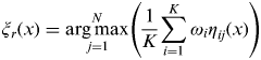 $$\xi _r (x) = \mathop {\arg \max} \limits_{\,j = 1}^N \left( {\displaystyle{1 \over K}\sum\limits_{i = 1}^K {\omega _i \eta _{ij} (x)}} \right)$$
where ω i(i⩽K) is the feature weight, which is derived using the error minimum on the training set.
2.2.2. Dempster-Shafer Approach
The Dempster-Shafer (D-S) approach (Shafer, Reference Shafer1976; Murphy, Reference Murphy2000; Dempster, Reference Dempster2008) has been widely used in data fusion. It uses D-S combination rules to integrate multiple features information to achieve optimal association. Assume that the feature set of M targets in SAR image is R 1,R 2,…,R M, Ri={a 1,a 2,…,a K}, and the feature set of N AIS-report targets is Q 1,Q 2, …,Q N, Qj={a 1,a 2,…,a K}. al is the lth (l⩽K) feature. Consider each feature as one class so as to get S(S⩽K) classes (equivalent S evidences). The matching measure of each class (corresponding feature at,t⩽S) between the ith target in SAR image and jth target in AIS report is  $E_{_{ij}} ^{a_t} $, and then to establish the basic belief function of each class:
 $$ E_{{i \leftrightarrow j}} ^{a_t} = \left\{ {\matrix{ {E_{ij} ^{a_t},}& {{\rm} i \leftrightarrow j} \cr {1 - E_{ij} ^{a_t},}& {\overline {i \leftrightarrow j} }\cr}} \right.$$
After acquiring S matching evidences, using existing or other improved DS conflict evidence combination rules to suppress the conflicts of S classes. The integrated matching measure of the ith target in the SAR image and jth target in the AIS report can be denoted as E i↔j. Additionally, weighted processing can also be carried out according to the belief of each feature before the combination. Using the method above, matching measures of other pairwise targets could also be derived. Then the M×N matrix of integrated matching measures can be formed, and the final decision can be made.
2.2.3. Fuzzy Integration
Fuzzy reasoning (Lu and Yamaoka, Reference Lu and Yamaoka1997; Zimmermann, Reference Zimmermann2010) is an important approach for fusion decisions. Construction of the factor set, determination of the weights and constitution of the evaluation set are vital in data association using fuzzy integration. On consideration of the contribution of different features to the final decision, the association based on a single feature is considered to be one factor. The weights of the different feature could be determined by experience or expert knowledge, and revised in practice. The evaluation set is the assessment for association accuracy, either expressed by fuzzy language or real number. Suppose that the factor set is A={a 1,a 2,…a S}, with a i the association result based on single feature information. The weight set is W={w 1,w 2,…w K}, with w i the weight of ith feature. The evaluation set is B={b 1,b 2,…b K}. The final decision is a fuzzy set based on evaluation set B, denoted as Z={z 1,z 2,…z K}. The fuzzy evaluation for the ith feature is denoted as Q i={q i1,q i2,…q iN}. The fuzzy matrix is made up of fuzzy evaluation for the associations based on all the features:
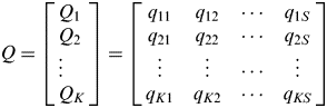 $$Q = \left[ \matrix{Q_1 \cr Q_2 \cr {\rm} \vdots \cr Q_K } \right] = \left[ {\matrix{ {q_{11}} & {q_{12}} & \cdots & {q_{1S}} \cr {q_{21}} & {q_{22}} & \cdots & {q_{2S}} \cr \vdots & \vdots & \cdots & \vdots \cr {q_{K1}} & {q_{K2}} & \cdots & {q_{KS}} \cr}} \right]$$
Then the integrated fuzzy evaluation matrix:
 $$Z = BQ$$
3. SHIP IDENTIFICATION AND TRACKING
Ship identification and tracking are significant to marine applications. This section gives further research on ship identification and tracking. Multi-sensor data fusion is also investigated.
3.1. Ship identification
Not all ships are equipped with or operate AIS, so some ships might not be reported by AIS but detected in SAR images. Meanwhile, the performance of state-of-the-art ship detection algorithms may not be satisfactory, particularly under high sea-state conditions, so some ships could be detected by AIS but not SAR. Therefore, there are four conditions to be considered (Figure 3).
• Case I: The ship detected in the space-borne SAR image could be successfully associated with the corresponding vessel from an AIS report. In this case, ship identification is achieved using the validated information derived from the AIS report.
• Case II: The ship detected in the space-borne SAR image does not have the corresponding vessel from an AIS report. False alarm discrimination should be carried out. As illustrated in section 3.3.1, many algorithms exist that may be used to discriminate. If it is a false alarm, it is eliminated directly. If not, the algorithms of SAR ship identification are used. The methods based on syntactic pattern recognition, fuzzy classification, neural networks (Osman et al., Reference Osman, Pany, Blosteiny and Gagnonz1997), 3D models and silhouette matching (Knapskog, Reference Knapskog2010), polarimetric information (Touzi et al., Reference Touzi, Raney and Charbonneau2004), superstructure moment invariants (Premaratne et al., Reference Premaratne and Safaei2009), scattering feature and structural feature, etc., can be performed. The optimal ship feature choice and an effective design of ship classifier are necessary. Additionally, the fact that no available pairwise AIS snapshots around the SAR image acquisition time exist, does not mean that the corresponding AIS reports for a ship detected in the SAR image definitely do not exist. Using data mining techniques could possibly extract the correlated AIS reports within a shorter time span.
• Case III: The ship from an AIS report cannot be associated with any of the ships detected in the space-borne SAR image. Firstly, ship detection should be carried out again to confirm whether there are missing targets or not. The missing alarm may be caused by strong sea clutter, and possibly the detection method performs less well such that small ships can hardly be detected. Improving the sea clutter modelling methods is one method, and detection of small ships in the transform domain may outperform other methods. Secondly, AIS false alarm discrimination should also be considered. An AIS false alarm may be caused either by technical or factitious factors. For example, a transmission error, encoding error, decoding error and an operator sending incorrect information are all possible reasons. Checking for the AIS report transmission error can use the Cyclic Redundancy Check (CRC) mentioned above effectively. As to the validation of AIS data itself, verification is easier. On consideration of the dynamic message from the AIS report, as long as no encoding and decoding errors exist, it is difficult to judge its authenticity. Maybe the combination with SAR missing alarm detection offers more benefits. Assume that the AIS-report position information is accurate, and identify that the ship belongs to large, medium or small size according to the size information from the AIS report. After the processing of position projection and position prediction, if the ship is large or medium-sized, there should be relatively obvious Radar Cross Section (RCS) within a smaller searching area centring at the AIS-predicted position. If not, it is likely an AIS false alarm.
• Case IV: Both are not detected, no process.
Flowchart of ship identification.
Figure 4 presents an example of ship identification by the integration of SAR and terrestrial AIS near Manila. The ships numbered 2, 3 and 5–13 are well correlated with AIS reports for Case I. Ships numbered 1 and 4 have no corresponding AIS reports, and are Case II. After false alarm discrimination, they are both real ship targets and need to be identified, relying on SAR. However, using existing identification results of ship targets validated by AIS (ships 2, 3 and 5–13) to classify ships 1 and 4 based on feature extraction of ship slices (or templates) may also be feasible.
Ship identification results by the integration of SAR and AIS (Ship pictures from MarineTraffic.com).
3.2. Ship Tracking
Ship tracking has been widely used in many applications including maritime security, environmental monitoring and search and rescue. Different applications require different response mechanisms. Though space-based AIS has more advantages for ship tracking with larger coverage and higher time resampling rate, ship-borne AIS equipment may be switched off or even be damaged in circumstances such as anti-piracy operations, oil spill polluter tracking and other suspicious activities. To take the oil spill issue as an example, the shipmaster may not operate the AIS equipment to avoid being tracked, so relying on AIS only would not always be an efficient method of dealing with this issue. Space-borne SAR imagery can provide complementary added value products, including maps of oil-polluted areas, high-resolution wind fields and detected ships. Meanwhile, there are weaknesses for SAR detection, including positive false alarms arising from wind/sea conditions, convergence at the interface of two water masses, up-welling effects, and poor time sampling in the low average revisit time constrained by the satellite orbit (Kerbaol, Reference Kerbaol2006). To extract the oil discharge, pollutant or ship feature appearing in a SAR image is practical. A flowchart of the application in oil spill ship tracking by integration of space-borne SAR and AIS is presented in Figure 5. It includes two main steps - discovering and tracking. Other applications are similar but characterized by themselves, so the detailed operations should be designed following particularity and practicality.
Flowchart of oil polluter track using space-borne SAR and AIS.
3.3. Multi-Sensor Data Fusion
Ship surveillance by the integration of multiple heterogeneous sensors is multi-sensor data fusion. There are two main problems to be considered. Firstly, the difficulty in acquiring cooperative data from different sensors in time requires the cooperation of significantly different sensors. As mentioned above, TerraSAR-X2 with secondary payloads (AIS and Infra-Red) on the same satellite platform would benefit the cooperative processing of heterogeneous data fusion. On the other hand, how to generate near real-time ship surveillance results displayed by using effective fusion techniques needs to be investigated. The multi-sensor information fusion model can be established and anomaly detection could be used to quantify the value of sensor data for ship surveillance performance (Guerriero, Reference Guerriero, Willett, Coraluppi and Carthel2008). Though many improved methods based on the Multi-Hypothesis Test (MHT) and Joint Probabilistic Data Association (JPDA), etc., have been developed, they need to be developed further to achieve better performance. Multi-sensor data fusion includes fusion of the same data formats (such as SAR and optical images) and fusion of different data formats (such as SAR images and AIS reports). The research on data fusion of space-borne SAR and AIS benefits multi-sensor data fusion, and may provide references for other heterogeneous data fusion. Additionally, in the multi-sensor ship surveillance model, the SAR tasking strategy should also be well planned for the fusion strategy with AIS reports.
4. DISCUSSION
Limited by sensor development and the state-of-the-art data processing methods, there are still many problems to be resolved in the fundamental research and the applications of ship surveillance by integration of space-borne SAR and AIS.
The main difficulties and challenges include:
• Systematic errors are unavoidable, such as the accuracy of geometric calibration for the SAR image (especially for open sea) and the validity of AIS reports. Systematic errors could be reduced with the development of sensors and data processing techniques.
• Ship detection under high sea-state conditions and identification using space-borne SAR images. Many ship detection algorithms have been developed, but ship classification or identification is still an open issue. Under the high sea-state (stronger sea clutters) conditions, ship detection based on the state-of-the-art algorithms is also difficult.
• Validation of the data association algorithms for high-density-shipping or high-sea-state conditions, and effective fusion decision criteria. Not only data association based on single features needs to be improved, the association methods based on multiple features also need improvement. The practicality of the search for better fusion decision criteria is still to be validated.
• Multi-sensor data fusion and real-time ship surveillance engineering applications. Multiple sensors (SAR, AIS, and Infra-Red, etc.) fusion for ship surveillance is a likely future development, and is based on the abundant fundamental research.
5. CONCLUSIONS
With the rapid development of space-borne SAR and AIS, integrated ship surveillance using these systems will play an important role in many applications.
This paper emphasises the need to investigate improved data association methods, ship identification, ship tracking and multi-sensor data fusion. More efforts will need to be focused on the development of effective algorithms for data association and fusion decision making. Meanwhile, the fundamental research on ship detection and identification based on space-borne SAR images should also be developed to solve the non-associated problems (e.g., no AIS report corresponding to the detected ship in the SAR image). Additionally, research on the data fusion of multi-mode space-borne SAR and AIS is also necessary. The investigations into applications to deal with the various maritime issues require more effort, and engineering solutions are needed to satisfy the increasing demands.
ACKNOWLEDGEMENTS
This work is supported partly by the National Natural Science Foundation of China under Grant 61240058 and the Fund of Innovation provided by the Graduate School of NUDT under Grant S130401.



