Introduction
Advanced Wi-Fi technologies like Wi-Fi 7 come with huge bandwidth to cover both 5 GHz Wi-Fi frequency ranges (5.1−5.8 GHz) and 6 GHz Wi-Fi frequency ranges (5.925−7.125 GHz). The data rates can be improved by 3 times in the Wi-Fi 7 by utilizing double the channel bandwidth of Wi-Fi 6E applications. The transmitting antenna should be designed to cover the entire bandwidth from 5.1 to 7.125 GHz to cover both frequency bands and to provide service to a large number of users. To extend the coverage area of a Wi-Fi signal, the antenna needs to have a high gain. Furthermore, the antenna should be circularly polarized to get around the drawbacks of linearly polarized antennas. It is quite challenging to generate circular polarization (CP) without employing conventional techniques like an L-shaped structure, slit, slot, or truncated corner to the patch [Reference Bernard, Chertier and Sauleau1–Reference Srinivas and Sanjeeva Reddy17].
In the published literature, an array of patches that make up a metasurface is sandwiched between dielectric substrates beneath the radiating element to enrich the impedance bandwidth of the patch [Reference Mosallaei and Sarabandi18]. An array of patches with suitable reflection phases is sandwiched beneath the dipole antenna to prototype a CP broadband antenna [Reference Yang and Rahmat-Samii19]. An array of rectangular patches is sandwiched beneath the square patch filled with 45° slots to prototype a CP broadband antenna [Reference Bernard, Chertier and Sauleau1]. An array of 4 × 6 rectangular patches is sandwiched below the square patch with truncated corners to prototype a CP broadband antenna [Reference Nakamura and Fukusako2]. An array of rectangular loops is sandwiched beneath the rectangular patch filled with a slot to prototype a CP broadband antenna [Reference Nasimuddin, Chen and Qing3]. An array of patches filled with slots is sandwiched beneath the patch filled with the complementary C-shaped slot to prototype a CP broadband antenna [Reference Jash, Goswami and Ghatak4]. In the above-discussed papers [Reference Bernard, Chertier and Sauleau1–Reference Jash, Goswami and Ghatak4, Reference Mosallaei and Sarabandi18, Reference Yang and Rahmat-Samii19], the metasurface is sandwiched between the radiating element and the ground plane.
In some other published papers [Reference Ta and Park5–Reference Guthi and Damera11], an array of patches that make up a metasurface is used above the radiating element to prototype a CP broadband antenna. An array of 4 × 4 patches is used as a metasurface above the truncated corner patch as a radiating element in [Reference Ta and Park5] and an L-shaped aperture as a radiating element in [Reference Cao, Zhang, Hong and Jin6, Reference Guthi and Damera7] to prototype a CP broadband antenna. An array of patches with truncated corners in [Reference Ta and Park8, Reference Guthi and Damera9], an array of rectangular loops in [Reference Liu, Huang, Liu, Cai, Xiong and Guo10], and an array of slot-loaded patches in [Reference Guthi and Damera11] are used as a metasurface. This array of metasurface patches is excited by slot radiating structure to prototype a CP broadband antenna. An array of patches used as metasurface below the radiating element and superstrate is used above the radiating element to prototype a CP broadband antenna [Reference Budarapu, Sunder and Ramakrishna12–Reference Guthi and Damera15]. The metasurface-based CP broadband multiple-input and multiple-output (MIMO) antenna is designed in [Reference Guthi and Damera16, Reference Srinivas and Sanjeeva Reddy17]. The CP broadband antenna has been constructed in the previously mentioned research studies [Reference Bernard, Chertier and Sauleau1–Reference Srinivas and Sanjeeva Reddy17], employing L-shaped structures, slit, slot, and truncated corner methods.
In this paper, CP is realized without employing conventional techniques like an L-shaped structure, slit, slot, or truncated corner to the patch. The radiating element is chosen in the shape of G and the probe feed is given to produce two resonating lengths with a length difference of λ/4. An arrangement of rectangular patches is sandwiched beneath the G-shaped patch to improve the impedance bandwidth, gain, and axial ratio bandwidth.
G-shaped patch antenna
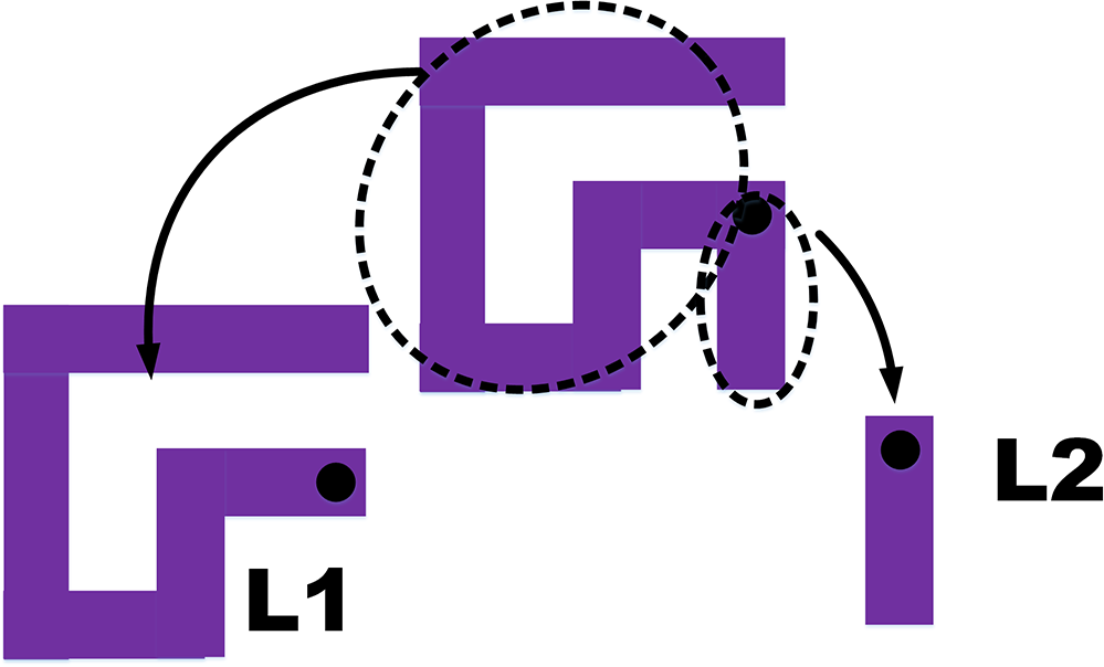
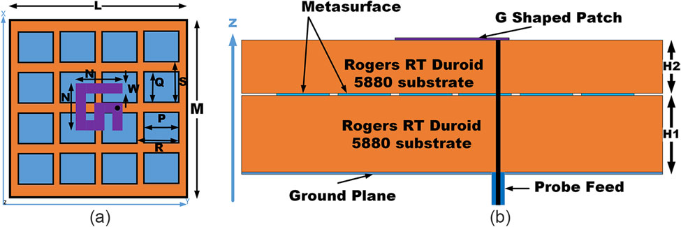
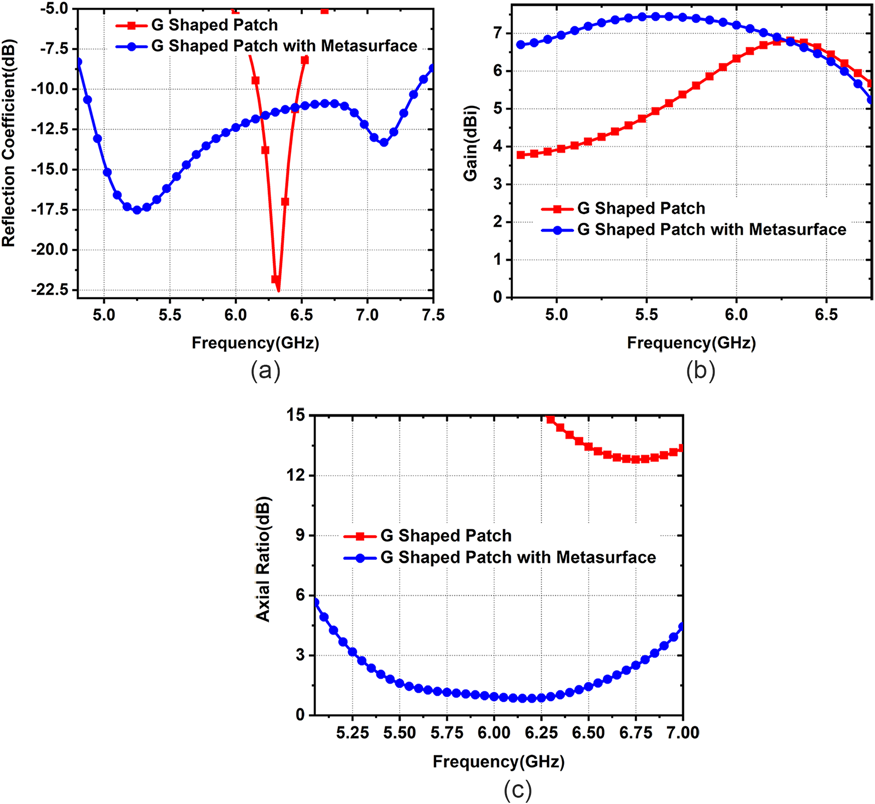
The radiating element is trimmed in the shape of G on grounded Rogers RT/Duroid 5880 substrate and the probe feed is given to produce two different resonating lengths with a length difference (L1−L2) of λ/4 as shown in Fig 1. The total phase difference for the λ/4 length difference is around 90°. The radiating element is fastened to the SMA connector’s inner conductor, while the ground plane is fastened to its outer conductor as shown in Fig. 2. The simulations are performed by using Ansys HFSS, and the simulation results are shown in Fig. 3. The G-shaped patch antenna has shown an impedance bandwidth of 5% (6.16−6.48) and a peak gain of 6.3 dBi.
G-shaped patch with its arms.

G-shaped patch with metasurface: (a) top view and (b) side view.

Simulation results of G-shaped patch and patch with metasurface: (a) reflection coefficient, (b) gain, and (c) axial ratio.

G-shaped patch with metasurface
The periodic array of 4 × 4 rectangular patches is arranged in the middle of the radiating patch and ground plane as shown in Fig. 2. In the case of a G-shaped patch with a perfect electric conductor (PEC) ground plane, the radiating element current and image currents of the radiating element in the PEC ground plane are placed closely and parallel to each other [Reference Mosallaei and Sarabandi18]. So, the G-shaped patch alone could not produce broadband resonance because coherent image currents are not formed over a broadband frequency range due to the cancellation of image currents with radiating element currents [Reference Mosallaei and Sarabandi18]. In this case, matching input impedance is very difficult and cannot produce the proper impedance matching for a wide range of frequencies.
In the case of a G-shaped patch with a metasurface structure, the metasurface is designed to cancel the fields produced by the image of currents of the radiating patch. The metasurface is designed with a proper reflection coefficient.
 \begin{equation*}{{\pi = }}\frac{{\eta - {\eta _o}}}{{\eta + {\eta _o}}}\end{equation*}
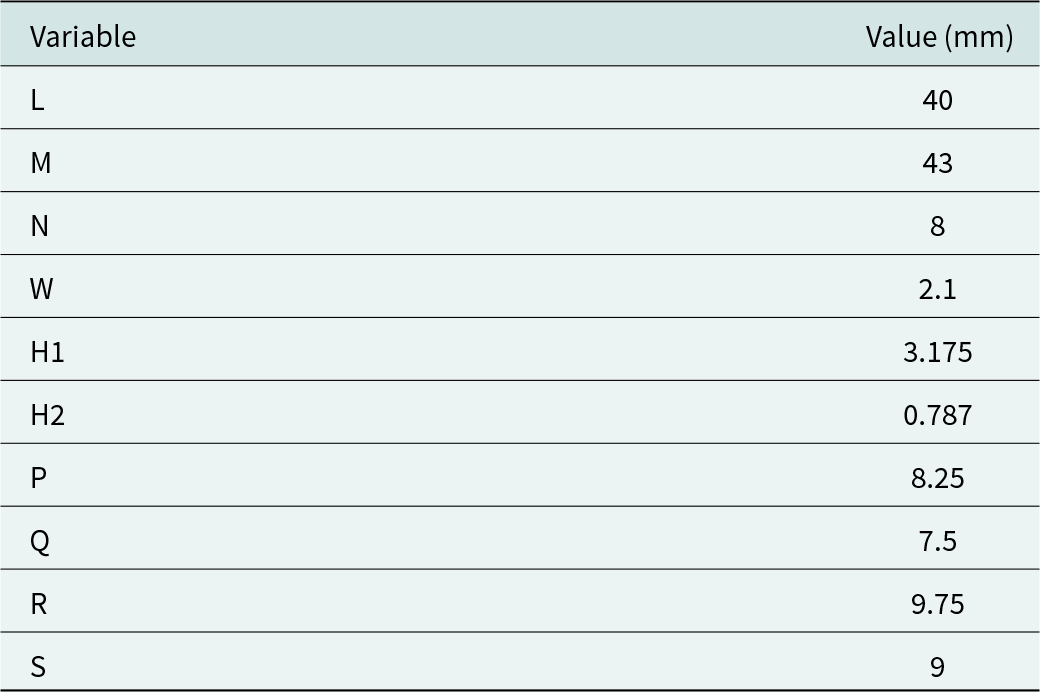
The reflection coefficient has to be unity magnitude, and the reflection phase should vary from −180° to 180° with purely reactive impedance to ensure the total reflection [Reference Mosallaei and Sarabandi18]. So, the coherent fields are produced on the radiating patch. The periodic array of patches could produce coherent image currents over broadband frequency ranges [Reference Mosallaei and Sarabandi18]. Hence, the impedance bandwidth can be improved over broadband frequency ranges. The rectangular patches in the metasurface can produce large phase variations over square patches in the metasurface [Reference Nakamura and Fukusako2]. So, the axial ratio bandwidth is improved for the rectangular patches in the metasurface [Reference Nakamura and Fukusako2]. The design parameter values are given in Table 1.
Design values

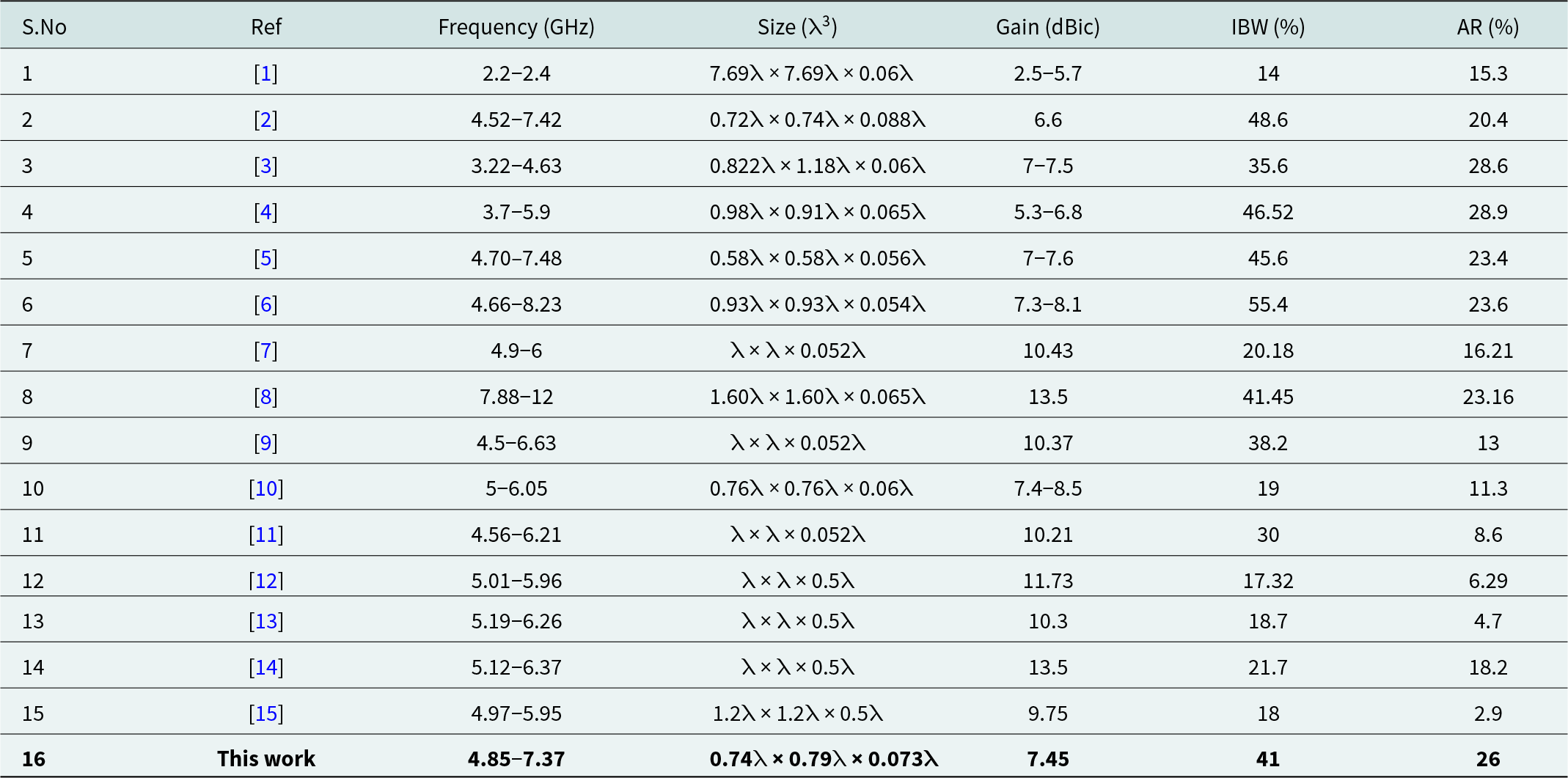
The G-shaped patch with metasurface structure is simulated using Ansys HFSS simulation software. It is evident that the antenna gain has increased to 7.45 dBic as shown in Fig. 3 and that the metasurface construction has improved the impedance bandwidth to 41% (4.85−7.37 GHz). Furthermore, the bandwidth of the axial ratio is enhanced to 26% (5.26−6.83 GHz).
Vary arm length “N”
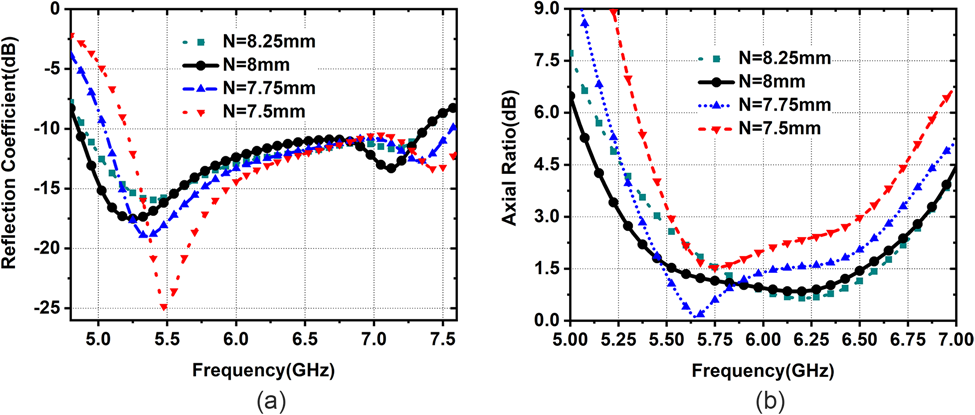
The parametric study is executed by changing the dimensions of the length of the patch “N” as plotted in Fig. 4. It can be perceived that the length of 8 mm gives the best results in terms of impedance bandwidth and axial ratio bandwidth.
Variation w.r.t. “N”: (a) reflection coefficient and (b) axial ratio.

Vary arm width “W”
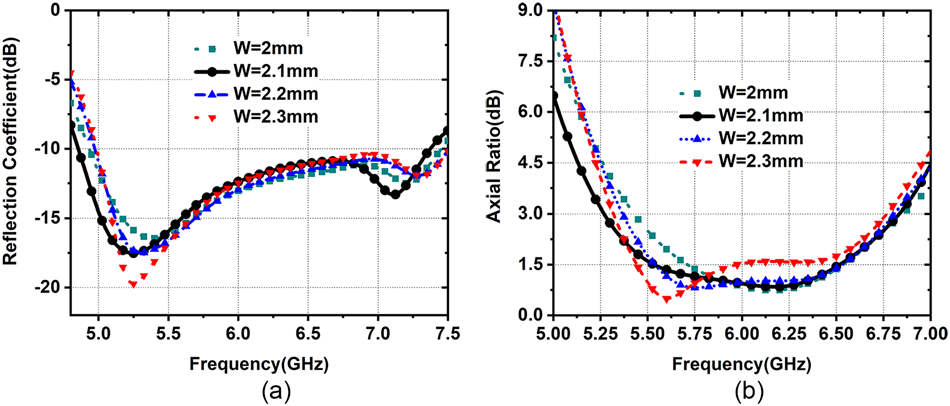
The parametric study is executed by changing the dimensions of the width of the G-shaped patch “W” as shown in Fig. 5. It can be perceived that the width of 2.1 mm gives the best results in terms of impedance bandwidth and axial ratio bandwidth.
Variation w.r.t. “W”: (a) reflection coefficient and (b) axial ratio.

Vary metasurface patch dimension “P”
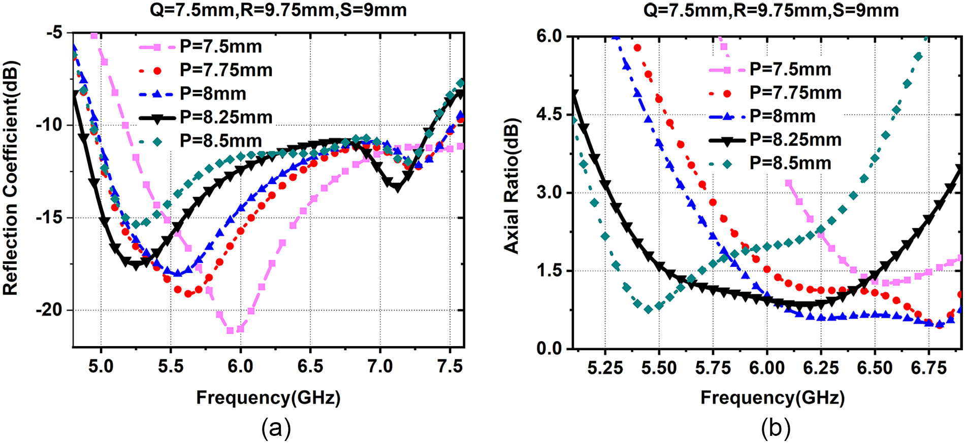
The parametric study is executed by changing the dimensions of the metasurface patches “P” as shown in Fig. 6. It can be perceived that the dimension of 8.25 mm gives the best results in terms of impedance bandwidth and axial ratio bandwidth.
Variation w.r.t. “P”: (a) reflection coefficient and (b) axial ratio.

Vary metasurface periodicity “R”
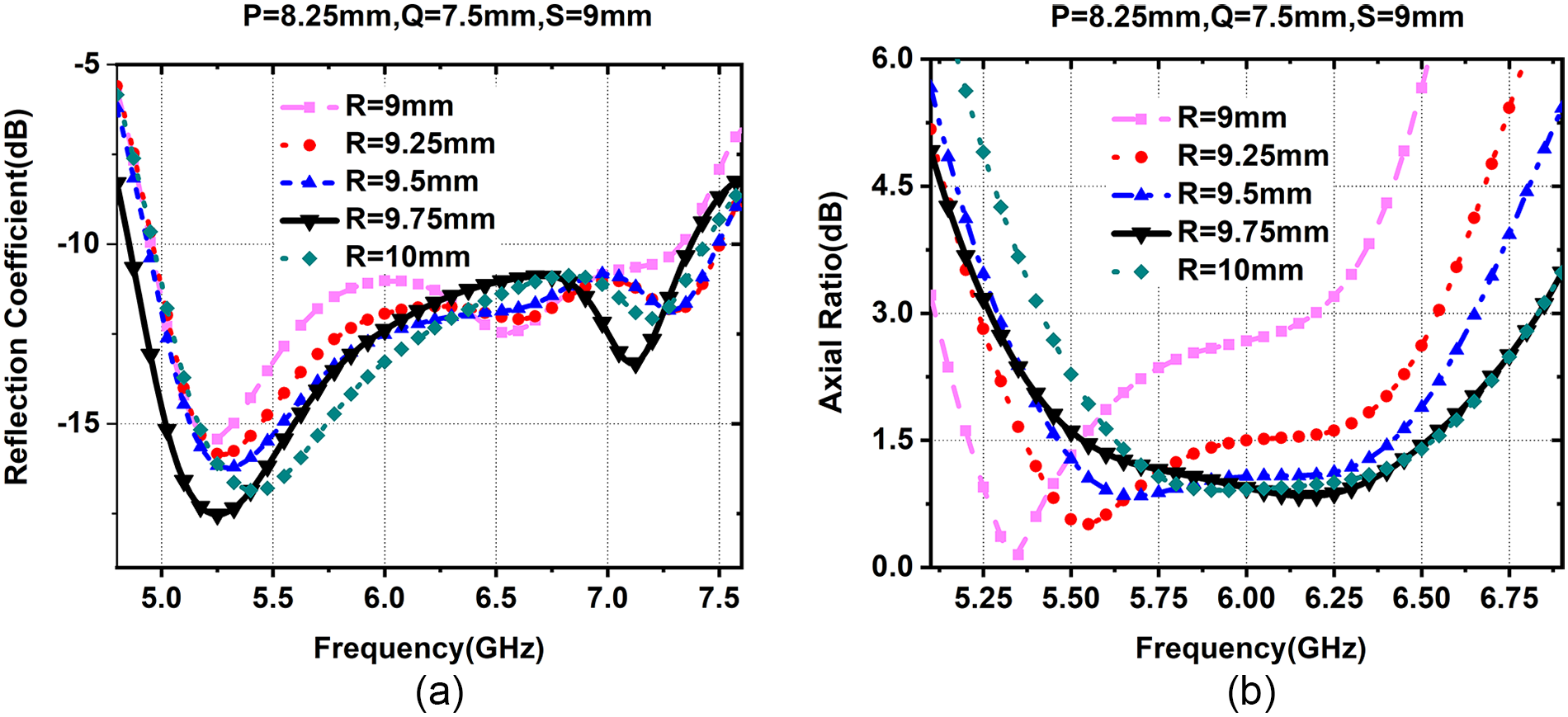
The parametric study is executed by changing the periodicity of the metasurface patches “R” as shown in Fig. 7. It can be perceived that the dimension of 9.75 mm gives the best results in terms of impedance bandwidth and axial ratio bandwidth.
Variation w.r.t. “R”: (a) reflection coefficient and (b) axial ratio.

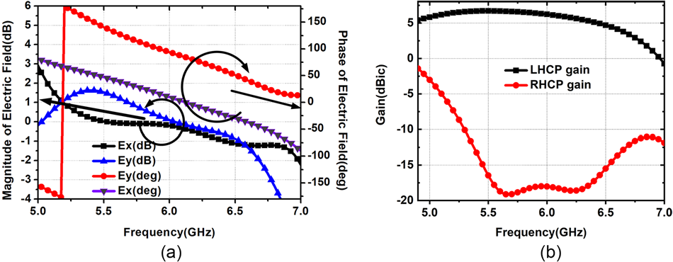
Ansys HFSS software is used to plot the antenna’s orthogonal fields. It is evident that the magnitude difference is less than 3 dB and the 90°-phase difference is maintained throughout a resonant frequency range as plotted in Fig. 8a. The left-hand circular polarized (LHCP) gain is high and the right-hand circular polarized (RHCP) gain is less throughout a resonant frequency range as shown in Fig. 8b. As a result, the antenna exhibits LHCP throughout a resonant frequency range.
(a) Orthogonal fields and (b) LHCP gain and RHCP gain.

The proposed antenna results are compared with other research studies in Table 2. The CP broadband antenna has been constructed in the previously mentioned research studies employing L-shaped structures, slit, slot, and truncated corner methods [Reference Bernard, Chertier and Sauleau1–Reference Srinivas and Sanjeeva Reddy17]. In this paper, the CP broadband antenna is designed without using regular structures like L-shaped structures, slit, slot, and truncated corner methods.
Antenna performance comparison table

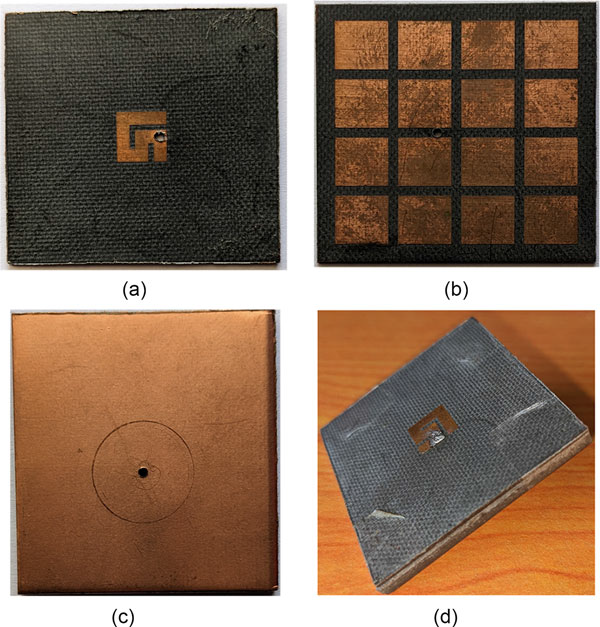
The proposed antenna fabricated prototype is shown in Fig. 9. The simulated and measured results are plotted in Fig. 10. It can be observed that the measured results almost replicate the simulation results. The radiation patterns are plotted in Fig. 11.
Fabricated model of the proposed antenna: (a) G-shaped patch, (b) metasurface, (c) ground plane, and (d) 3D view.

Comparison of simulated and measured results: (a) reflection coefficient and (b) gain and axial ratio.

Radiation patterns at (a) 5.5 GHz, (b) 6 GHz, and (c) 6.5 GHz.

Conclusion
A CP broadband antenna is designed without employing conventional techniques like L-shaped structure, slit, slot, or truncated corner to the patch. The G-shaped patch antenna is designed at 6.3 GHz. The metasurface of a 4 × 4 array of periodic patches is sandwiched beneath the G-shaped patch to improve the impedance bandwidth, gain, and axial ratio bandwidth. The designed antenna is useful to provide broad bandwidth for Wi-Fi 7 applications.
Competing interests
All authors declare that they have no conflict of interest. The authors declare that they have no known competing interests or personal relationships that could have appeared to influence the work reported in this paper.

Dr. Guthi Srinivas received his M.Tech degree in Communication Systems from MNNIT Allahabad, Allahabad, India, in 2014 and his PhD degree from the National Institute of Technology, Warangal, India, in the field of high gain and broadband antennas for 5 GHz Wi-Fi applications. Currently, he is working as an assistant professor at B V Raju Institute of Technology, Narsapur, Medak. His research interests include metasurface antennas, superstrate antennas, MIMO antennas, and circularly polarized antennas.

Dr. B.R. Sanjeeva Reddy received his ME degree in Microwaves from the Government College of Engineering, Pune, India, and his PhD degree from the National Institute of Technology, Warangal, India, in the field of multiband antennas. Currently, he is working as a professor at B V Raju Institute of Technology, Narsapur, Medak. His areas of interest include computational electromagnetics, wearable antennas, and metamaterials.

Dr. Ratikanta Sahoo received his M.Tech degree in Communication System Engineering from VSSUT, Burla, India, in 2012 and his PhD degree in RF and Microwave from the National Institute of Technology, Warangal, India, in 2020. Currently, he is working as an Assistant Professor at Sri Vishnu Engineering College for Women, West Godavari. His research interests include conformal antenna design, metamaterial, and THz antenna.