I. INTRODUCTION
The spontaneous formation of complex microstructures during the directional solidification of alloys is a permanent topic of both fundamental and applied interest.Reference Lo, Karma and Plapp1 Peritectic solidification widely exists in many technologically important materials, such as TiAl alloys, Cu-based alloys, Co-based superalloys, high Tc superconductors, rare earth permanent magnetic compounds, and other high temperature structure alloys.Reference Kerr and Kurz2–Reference Vandyoussefi, Kerr and Kurz7
Under large G/V ratios (G is the temperature gradient, V is the pulling velocity) during directional solidification, many complex microstructures, e.g., peritectic coupled growth (PCG), cellular peritectic coupled growth (CPCG), discrete bands and island bands were found in peritectic systems.Reference Kerr and Kurz2,Reference Vandyoussefi, Kerr and Kurz7–Reference Trivedi and Park11 And several models have been proposed to describe the formation mechanisms of these structures. Convection has an important influence on the evolution of the microstructures. For example, an oscillating tree-like structure is induced by convection in peritectic systems, especially when the diameters of the samples are large.Reference Park and Trivedi9 Mazumder et al.Reference Mazumder, Trivedi and Karma12 found that an oscillatory fluid flow induces the formation of the structure of tree-like primary phase surrounded by the peritectic phase.
The influence of convection on the interface morphologies and the primary arm spacing has been studied in Al–Cu, Al–Li, Pb–Tl, and Pb–Bi alloys.Reference Trivedi, Miyahara, Mazumder, Simsek and Tewari13–Reference Trivedi, Liu, Mazumder and Simsek16 During directional solidification, when the solute atoms are lighter than the solvent atoms, double diffusive convection is generated by buoyancy because of the combination of temperature and concentration gradients. By now, the effect of double diffusive convection on the morphology and structure of the peritectic two phases is rarely studied. In peritectic alloys, whether there is another microstructure which also forms under convection conditions has not been reported.
At the peritectic temperature T P, the three phases are in equilibrium with each other, according to Gibbs’ phase rule at constant temperature and pressure. In peritectic microstructure, peritectic reaction occurs at  $T_{\rm{P}}^{\rm{K}}$ (below T P), which is characterized by the remelting of the primary phase.Reference Fredriksson and Nylen17–Reference Phelan, Reid and Dippenaar19 The undercooling (T P −
 $T_{\rm{P}}^{\rm{K}}$) provides a driving force for the remelting of the primary phase.
 $T_{\rm{P}}^{\rm{K}}$ is called as the kinetic temperature of peritectic reaction.
In this paper, the separated structure of the ζ-Cu5Ge and α-Cu phases was observed under double diffusive convection conditions in directional solidified Cu–Ge peritectic alloys. The two-phase separated process is characterized by the formation of a large triple-phase region of peritectic reaction and a big α cell. Based on the experimental results, the formation mechanism of the two-phase separated structure was qualitatively analyzed. During peritectic reaction, the morphologies of the large triple-phase region of the two-phase separated structure were investigated.
II. EXPERIMENTAL PROCEDURE
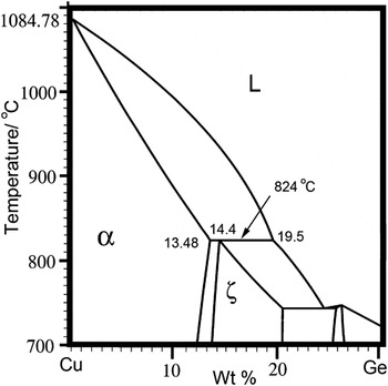
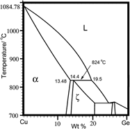
In this study, Cu100−xGex(x = 13.9, 14.5, 15.6, 16.8, and 17.3 wt%) peritectic alloys were produced from 99.99% pure Cu and Ge, and directionally solidified in a two heating-zone Bridgman type furnace. The phase diagram of peritectic Cu–Ge alloy is shown in Fig. 1. The directional solidification was conducted under a controlled Ar atmosphere of 30 kPa pressure. The samples of 1.8 mm in diameter placed in alumina crucibles of 2 mm in inner diameter were pulled at selected velocities (V = 2, 3, 5, 10 μm/s). At the end of directional solidification, the crucibles were dropped into Ga–In–Sn liquid alloy to quench the solid/liquid interface. Temperature profiles were measured using a PtRh30-PtRh6 thermocouple inserted down the center of the samples and the temperature gradient was deduced from the temperature profiles.
Part of the phase diagram in a Cu–Ge system.Reference Wang, Jin, Leinenbach and Jacot20

III. RESULTS AND DISCUSSION
A. Microstructure
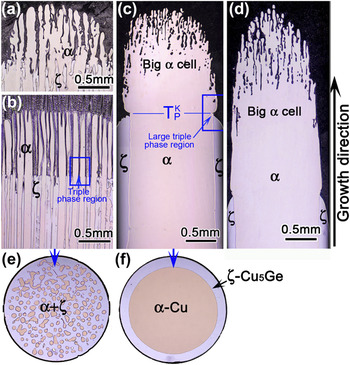
Figure 2 shows the longitudinal and transverse sections of the samples with different alloy compositions which were directionally solidified at G = 25 K/mm and V = 3 μm/s. CPCG is observed in 17.3 and 16.8 wt% Ge peritectic alloys, as shown in Figs. 2(a) and 2(b).Reference Dobler, Lo, Plapp, Karma and Kurz8 During CPCG, cellular α and cellular/planar ζ grow toward liquid by the weakly diffusion coupling between them, where α is a leading phase. The signs of peritectic reaction can be seen near the liquid/α/ζ trijunctions [Fig. 2(b)]. When the alloy composition C 0 is less than 14.5 wt% Ge, a completely two-phase separated structure is found in the samples, as shown in Figs. 2(c), 2(d), and 2(f), in which the primary α-phase locates in the center and is surrounded by the peritectic ζ-phase. It can be clearly seen from Figs. 2(c) and 2(d) that a big α cell corresponding to the axisymmetric pattern is formed firstly in the solid-liquid interface. At some temperature above  $T_{\rm{P}}^{\rm{K}}$, the cellular primary α-phases merge together to form a single cylinder. At
 $T_{\rm{P}}^{\rm{K}}$, the tubular peritectic ζ layer begins to grow around the cylindrical primary α-phase and a large triple-phase region of peritectic reaction forms [see Fig. 2(c)]. Different from the oscillating tree-like structure, the two-phase separated structures reach a steady state.
Microstructures of directionally solidified Cu–Ge alloys for different alloy compositions at V = 3 μm/s and G = 25 K/mm. (a) Cu–17.3 wt% Ge, (b) Cu–16.8 wt% Ge, (c) Cu–14.5 wt% Ge, (d) Cu–13.9 wt% Ge, (e) and (f) are the transverse sections of (b) and (c), respectively.

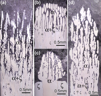
Figure 3 shows the changes in two-phase morphology with the growth conditions for Cu–15.6 wt% Ge alloy. For V = 10 μm/s, a mixed structure is observed consisting of both α dendrites and ζ dendrites, as shown in Fig. 3(a). At a lower pulling velocity, V = 3 μm/s, CPCG is obtained, as shown in Fig. 3(b). As the velocity decreases to 2 μm/s, the separated structure is obtained as shown in Fig. 3(c). However, when the temperature gradient (G) decrease to 10 K/mm and V = 2 μm/s, the mixed structure (CPCG) is observed again, as shown in Fig. 3(d).
Longitudinal microstructures taken at the quench front for Cu–15.6 wt% Ge: (a) G = 25 K/mm and V = 10 μm/s, (b) G = 25 K/mm and V = 3 μm/s, (c) G = 25 K/mm and V = 2 μm/s, and (d) G = 10 K/mm and V = 2 μm/s.

In the paper, the structures shown in Figs. 2(a) and 2(b) are called as conventional structures, and those shown in Figs. 2(c) and 2(d) are called as two-phase separated structures.
B. The formation mechanism of the two-phase separated structure
According to the experimental results, it is found that the formation of the two-phase separated structure is closely related to growth conditions and double diffusive convection. The process is characterized by the formation of a big α cell and a large triple-phase region of peritectic reaction.
1. The separation of the two phases in a peritectic system
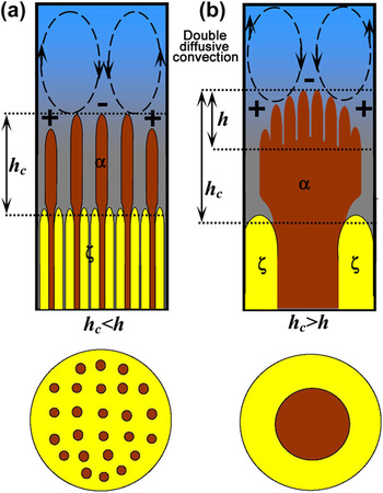
During directional solidification, the growth of the primary phase will reject the solute to the solid/liquid interface, and a concentration gradient will be formed in the liquid. As the density of the rejected solute (Ge) is lighter than Cu, double-diffusive convection is induced by the temperature and concentration gradients in the axial direction (see Fig. 4). Convective instability can change the shape of the solid/liquid interface. Drevet, Jamgotchian and Worster et al.Reference Drevet, Nguyen Thi, Camel, Billia and Dupouy15,Reference Jamgotchian, Nguyen Thi, Bergeon and Billia21,Reference Worster22 proved that the structure of the big α cell is induced by an axisymmetric convection (see Fig. 4), which is down-going along the center of crucible and flows upward along the sidewall of the crucible. The fluid flow directly pushes the rejected solute (Ge) from the center to the border of the crucible, which induces a lateral concentration gradient.
(a) Schematic diagram of CPCG h c < h [Figs. 2(a) and 2(b)], and (b) schematic diagram of the two-phase separated structure h c > h [Figs. 2(c) and 2(d)] (symbols + and − indicate excess and deficiency of Ge).

The wave lengths for calculating convective instabilities are in good agreement with the experimental observations. The critical wave length (λconv) of the convective instability is about 20 times the diffusion length DL/V.Reference Drevet, Nguyen Thi, Camel, Billia and Dupouy15,Reference Worster22–Reference Caroli, Caroli, Misbah and Roulet24 A value for DL ≈ 5 × 10⁻⁹ m2/s relevant for the present experiments is determined by the plane front growth limit criterion. The λconv value is about 3.3 cm (V = 3 μm/s), which is greater than the sample diameter Φ = 2 cm. Nguyen Thi et al.Reference Nguyen Thi, Billia and Jamgotchian25 found that, when the lateral confinement Φ/λconv is less than unity, the solid/liquid front always has a central axisymmetric core with downward flow in its central part. This result is similar to that obtained in the experiments where a big α cell is located in the middle of the samples [see Figs. 2(c) and 2(d), Φ/λconv ≈ 0.67]. When V = 10 μm/s (Φ/λconv ≈ 2), the effect of convection on the shape of the interface is not obvious [Fig. 3(a)]. The formation of the big α cell is a prerequisite for the formation of the two-phase separated structure, which provides lateral space for the growth of the peritectic phase. According to the lateral confinement condition (Φ/λconv < 1), the big α cell is obtained at lower speeds, and the speed limit for the steady growth of the big α cell can be expressed as
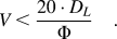 $$V \,\lt\, {{20 \cdot D_L } \over \Phi }\quad.$$
In Figs. 2(a) and 3(b), though a big α cell is formed (Φ/λconv ≈ 0.67) in the peritectic system, the two-phase separated growth is not obtained. Actually, the lateral confinement condition (Φ/λconv < 1) is necessary but not a sufficient condition for the separate growth of the two phases.
The distance h c, between α and ζ front [Figs. 4(a) and 4(b)], plays an important role in maintaining the two-phase separated growth. The length of the α cells, h, is defined as the distance between the tip and the root of the α cells [see Fig. 4(b)]. During CPCG, the distance (h) cannot be marked in Fig. 4(a) because peritectic reaction suppresses the mergence of the α cells. To visually express the evolution between the structures, h is presumed to be present in Fig. 4(a). When h c < h, peritectic reaction occurs around the discrete α cells to produce CPCG [Figs. 2(a), 2(b), and 4(a)]. When h c > h, the discrete α cells merge together and form a cylinder. Then the layered ζ-phase starts growing around it to produce a two-phase separated structure [Figs. 2(c), 2(d), and 4(b)]. In the mushy zone, the length of the α cells (h) is a function of the growth conditions (G, V, and C 0). In addition, to avoid the formation of band microstructures or oscillating tree-like structures, G/V should be smaller than the plane front growth limit of the primary phase.
Therefore, besides the lateral confinement condition (Φ/λconv < 1), the growth conditions also govern the two-phase separated process. Under convection conditions, it is difficult to express the length of the α cells quantificationally. As shown in Figs. 2 and 3, the two-phase separated structures are easier to gain at low alloy compositions, low pulling velocities (V) and high temperature gradients (G). This is because low alloy compositions and high G/V will lead to that the cells or dendrites spacing are relatively small, which means that the α cells need a short distance to merge together (h is shorter).
C. Peritectic reaction induced by the two-phase separated structure
1. Formation of the large triple region and its morphologies during peritectic reaction
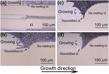
Figure 5(a) shows the conventional morphologies of the peritectic reaction regions, which are obtained in conventional structures [e.g., Figs. 2(a) and 2(b)]. These small regions of peritectic reaction form around the α cells, which is similar to the previous experimental results,Reference Fredriksson and Nylen17–Reference Phelan, Reid and Dippenaar19 and their geometrical morphologies of the triple-phase regions can not be observed very distinctly after quenching.
Microphotographs of the triple junction regions of the two-phase separated structure at G = 25 K/mm. (a) V = 3 μm/s and Cu–16.8 wt% Ge, (b) V = 5 μm/s and Cu–14.5 wt% Ge, (c) V = 3 μm/s and Cu–14.5 wt% Ge, and (d) V = 2 μm/s and Cu–14.5 wt% Ge.

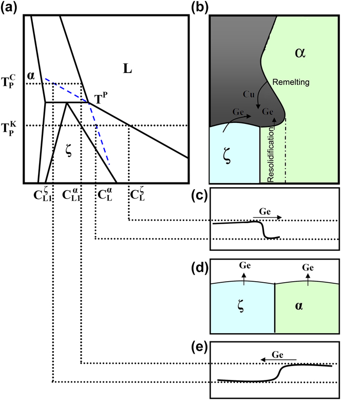
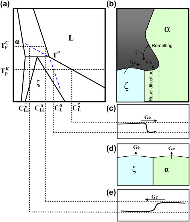
Following the formation of the two-phase separated structure, a large triple-phase region of peritectic reaction forms in the edge of the cylindrical α-phase because of the thick ζ-phase [see Fig. 2(c)]. The large triple-phase regions are shown in Figs. 5(b)–5(d), which are much bigger than those in Fig. 5(a). At  $T_{\rm{P}}^{\rm{K}}$, the peritectic ζ-phase begins to grow along the solid/liquid (α/L) interface. The solute rejected by the growing ζ-phase will lead to that the liquid phase is supersaturated with respect to the α-phase, which contributes to the remelting of the α-phase, see the schematic of Figs. 6(a)–6(b). The remelting α-phase supplies Cu atoms, which dilutes the liquid concentration of the triple region. Thus, the ζ interface is tilted [Figs. 5(b)–5(c)]. When the pulling velocity is lower, the solute distribution near the triple region is uniform and thus the ζ interface is perpendicular to the growth direction [Fig. 5(d)]. As the pulling velocity decreases from 5 to 2 μm/s, the growing ζ-phase changes from dendritic to near planar [Figs. 5(b)–5(d)]. At the large triple-phase region of peritectic reaction, the morphological instability of the peritectic interface under a high pulling velocity can be explained by the constitutional undercooling criterion.
Schematic of the triple phase region of peritectic reaction and PCG. (a) Peritectic phase diagram; (b) and (c) triple phase region of peritectic reaction and solute diffusion in liquid in contact to α and ζ at a undercooling below T P, respectively; (d) and (e) PCG and solute diffusion in liquid in contact to α and ζ at a negative undercooling above T P, respectively.
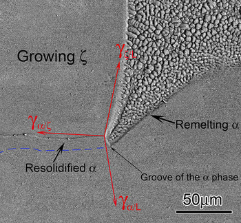
The resolidification phenomenon of the α-phase is observed near the triple junction, as shown in Figs. 5(b)–5(d). At the triple-phase junction, the Young–Laplace equation describing mechanical equilibrium must be satisfied:
 $${\rm{\gamma }}_{{\rm{\alpha }}/L} {\rm{\vec \tau }}_{{\rm{\alpha }}/L} + {\rm{\gamma }}_{{\rm{\varsigma }}/L} {\rm{\vec \tau }}_{{\rm{\varsigma }}/L} + {\rm{\gamma }}_{{\rm{\alpha /\varsigma }}} {\rm{\vec \tau }}_{{\rm{\alpha }}/{\rm{\varsigma }}} = 0\quad,$$
where  ${\rm{\vec \tau }}_{i/j}$ corresponds to the unit vector tangential to the i–j interface and pointing outward from the triple junction, while
 ${\rm{\gamma }}_{{\rm{\alpha }}/L}$,
 ${\rm{\gamma }}_{{\rm{\varsigma }}/L}$, and
 ${\rm{\gamma }}_{{\rm{\alpha /\varsigma }}}$ are the corresponding surface energies (see Fig. 7). Thus, a groove structure of the α-phase near the triple-phase junction must be required for the mechanical equilibrium, as shown in Fig. 7. Then the resolidification of the α-phase occurs in the groove.
Geometrical morphology of phases near the triple junction in Cu–14.5 wt% Ge solidified at G = 25 K/mm and V = 2 μm/s.

2. Coupling growth of the ζ-phase and the groove of α-phase at the triple junction region
As the ζ-phase grows, the resolidification of the α-phase occurs in the groove, and a near coupling growth of the two phases (the resolidified α and the growing ζ) forms in the vicinity of the triple junction [Figs. 5(b)–(d), Fig. 7]. According to the classic theory of peritectic solidification, coupling growth of the two phases forms when the G/V value is higher than the plane front growth limit of the primary phase and a negative undercooling (growth temperature above T P) must be required for the diffusion in coupled solidification of peritectic alloys.Reference Dobler, Lo, Plapp, Karma and Kurz8,Reference Kohler, Germond, Wagnière and Rappaz10 Figures 6(a), 6(d), and 6(e) show that at  $T_{\rm{P}}^{\rm{C}}$ (above T P) a liquid has higher Ge concentration. During coupling growth, liquid diffusion of Ge from the interface of α to the interface of ζ takes place.
However, during the growth of the two-phase separated structure, the peritectic reaction needs a kinetic undercooling,Reference Fredriksson and Nylen17–Reference Phelan, Reid and Dippenaar19 which means the temperature of the triple junction ( $T_{\rm{P}}^{\rm{K}}$) is lower than T P. Therefore, the diffusion couple of Ge in the vicinity of the triple junction is different from the classic theory of peritectic couple growth. At
 $T_{\rm{P}}^{\rm{K}}$ (below T P) the liquid composition in equilibrium with the α-phase is lower than the liquid in equilibrium with the ζ-phase [Fig. 6(a)]. Although the growth of the resolidified α rejects Ge to the groove, the remelting α will supply Cu atoms to the groove and the difference of equilibrium compositions between the resolidified α and the remelting α will decrease the liquid composition of the groove. Thus, there is a buildup of Ge atoms in front of the ζ-phase and depletion in the groove of the α-phase as shown in Fig. 6(c). Similar to temperatures below T E in eutectic coupling growth, liquid diffusion of Ge atoms toward the groove of the α-phase and Cu toward the interface of the ζ-phase occurs in the vicinity of the triple junction. Namely, the groove of α is an absorber of Ge. The diffusion coupling (Cu and Ge) keeps the stable existence of the α groove. And the resolidification of α forming in the groove is also attributed to the diffusion coupling between the groove of the α-phase and the interface of the ζ-phase under the constraint of mechanical equilibrium at the triple junction.
3. Migration of the groove of the α-phase
Figure 7 shows the typical morphology of the groove. During the migration of the groove, the remelting and resolidification of the α-phase occur at the high and low temperature side, respectively (see Fig. 7). However, at the lowest point (bottom) of the groove, the melting and solidification of the α-phase cannot occur concurrently at one point because the two process are contradictory and asymmetrical in kinetics. Thus, the motion of the lowest point (bottom) of the groove can be unstable.
IV. CONCLUSIONS
In summary, a two-phase separated structure has been observed under double diffusive convection conditions in a directional solidified Cu–Ge peritectic system. The formation of the two-phase separated structure is attributed to the interaction of double diffusive convection and growth conditions. The morphologies of the large trijunction region of the separated structure are investigated. The coupling growth of the ζ-Cu5Ge-phase and the groove of α-Cu near the trijunction is attributed to the diffusion coupling between the groove of the α-phase and the interface of the ζ-phase under the constraint of mechanical equilibrium.
The two-phase separated growth forms a cylindrical layered structure. Layered structural composites like some natural structures, e.g., plant stems and bone, have opened a land of promising applications in many fields: optics, electronics, mechanics, energy, environment, biology, medicine, fuels, solar cells and sensors. The growth process of the cylindrical layered structure is potentially useful for the synthesis of functionally layered materials.
ACKNOWLEDGMENTS
This work was supported by the National Natural Science Foundation of China (Grants Nos. 50901025 and 50975060), National Basic Research Program of China (Grant No. 2011CB610406), China Postdoctoral Science Foundation (Grant Nos. 201104420 and 20090450840), and “Fundamental Research Funds for the Center Universities” (Grant No. HIT.BRET1.20100008).