1. Introduction
Particle-laden turbulent flows, where turbulence interacts with dispersed solid particles, are common in both natural and industrial processes, such as sandstorms, sediment transport, fluidised beds and mineral flotation. These flows involve intricate fluid–particle interactions spanning a wide range of spatial and temporal scales, posing substantial challenges for both experimental measurements and numerical simulations (Balachandar & Eaton Reference Balachandar and Eaton2010; Brandt & Coletti Reference Brandt and Coletti2022; Marchioli et al. Reference Marchioli2025).
Previous studies have primarily focused on how turbulence influences particle drag, lift, spatial distribution and inter-particle interactions, as well as how particles modify flow characteristics such as mean velocity, turbulence intensity and energy transfer across scales (see reviews by Balachandar & Eaton Reference Balachandar and Eaton2010; Tenneti & Subramaniam Reference Tenneti and Subramaniam2014; Brandt & Coletti Reference Brandt and Coletti2022; Marchioli et al. Reference Marchioli2025). Despite considerable advances, most investigations have assumed spherical particles to simplify modelling and computational costs. However, in many real-world scenarios – such as ice crystals in the atmosphere, pulp fibres in papermaking and red blood cells in microcirculation – particles are non-spherical, often with complex or deformable shapes. Although growing attention has been paid to non-spherical particles in turbulent flows (see reviews by Voth & Soldati Reference Voth and Soldati2017; Marchioli et al. Reference Marchioli2025), the influence of particle shape on turbulence–particle interactions remains incompletely understood. To isolate shape effects while avoiding additional complexities, the present study focuses on rigid, axisymmetric particles, including prolate and oblate spheroids as well as finite-length cylinders.
Previous studies on the interactions between turbulence and axisymmetric particles have primarily focused on the following key aspects.
(i) Particle orientation: the anisotropic geometry of non-spherical particles causes their symmetry axis to preferentially align with specific flow structures in both isotropic and anisotropic turbulence. This alignment depends on the particle aspect ratio,
 $\lambda = L/D$
, where
 $L$
is the axial length and
 $D$
the equatorial diameter. Spheroidal particles are classified as oblate when
 $\lambda \lt 1$
and prolate when
 $\lambda \gt 1$
.
In homogeneous isotropic turbulence, Parsa et al. (Reference Parsa, Calzavarini, Toschi and Voth2012) showed that prolate spheroids and long cylinders tend to align their symmetry axis with the local vorticity. This behaviour arises from the coupling between particle orientation and local velocity gradients, which causes elongated particles to align with fluid stretching directions – often coinciding with the vorticity vector. In contrast, in anisotropic wall-bounded turbulence, Challabotla et al. (Reference Challabotla, Zhao and Andersson2015a ) found that non-inertial, sub-Kolmogorov-scale oblate spheroids preferentially align their symmetry axis normal to the wall in the near-wall region. As particle inertia increases, the preferred orientation shifts progressively toward the spanwise direction – a trend also reported by Eshghinejadfard, Zhao & Thévenin (Reference Eshghinejadfard, Zhao and Thévenin2018) for finite-size oblate spheroids. Marchioli, Zhao & Andersson (Reference Marchioli, Zhao and Andersson2016) observed that inertial prolate spheroids preferentially align with the mean flow direction near the wall, but that this trend weakens with increasing particle inertia or decreasing aspect ratio.
The aspect ratio plays a key role in determining alignment. For instance, Challabotla et al. (Reference Challabotla, Zhao and Andersson2015b ) observed that non-inertial prolate spheroids tend to align their symmetric axis with the streamwise direction near the wall, whereas oblate particles align normal to the wall. These trends are consistent with Jeffery’s theory for the rotation of ellipsoidal particles in simple shear flow (Jeffery Reference Jeffery1922a ). Extending beyond spheroidal shapes, Do-Quang et al. (Reference Do-Quang, Amberg, Brethouwer and Johansson2014) numerically studied finite-size rigid cylindrical fibres in turbulent channel flows and found that fibres with aspect ratios of 2, 6 and 15 preferentially aligned in the spanwise direction near the channel centre, transitioning to streamwise alignment closer to the wall.
(ii) Particle rotation: the rotation modes and angular velocities of non-spherical particles are shaped by their anisotropic geometry and corresponding variations in mass distribution. In homogeneous isotropic turbulence, Parsa & Voth (Reference Parsa and Voth2014) established a scaling law for the mean square tumbling rates of inertial rod-like particles, showing that
 $\langle \dot {p}_i\dot {p}_i\rangle \sim l^{-4/3}$
when the particle length
 $l$
falls within the inertial range. Here,
 $\dot {p}_i$
denotes the time derivative of the orientation vector.
In inhomogeneous wall-bounded turbulence, rotational dynamics is governed not only by particle inertia and aspect ratio, but also by local flow conditions. Zhao et al. (Reference Zhao, Challabotla, Andersson and Variano2015b ) investigated sub-Kolmogorov-scale spheroidal particles in turbulent channel flows, decomposing their rotation into tumbling (rotation about an axis perpendicular to the particle’s symmetry axis) and spinning (rotation about the symmetry axis). In the nearly homogeneous and isotropic region at the channel centre, prolate particles were found to exhibit higher spinning rates, whereas oblate particles exhibited higher tumbling rates – a trend consistent with observations in homogeneous isotropic turbulence (e.g. Byron et al. Reference Byron, Einarsson, Gustavsson, Voth, Mehlig and Variano2015).
Near the wall, Zhao et al. (Reference Zhao, Challabotla, Andersson and Variano2015b ) found that rotational behaviour changes markedly: inertial oblate particles exhibit the highest spinning rates, while inertial prolate particles show the highest tumbling rates – opposite to the trend observed at the channel centre. This reversal arises because inertial spheroids respond strongly to the local mean shear, which varies significantly across the channel. Moreover, they reported that increasing particle inertia tends to promote more isotropic rotation at the channel centre for both prolate and oblate particles, while enhancing rotational anisotropy near the wall. Baker & Coletti (Reference Baker and Coletti2022) showed that compared with disk-like short cylinders, fibre-like long cylinders are more sensitive to near-wall turbulence and tend to have much higher rotational rates in the near-wall region.
Previous point-particle simulations have further clarified fibre–fluid relative motion. Zhao, Marchioli & Andersson (Reference Zhao, Marchioli and Andersson2014) investigated the slip velocity of rigid fibres, modelled as highly prolate spheroids, and showed that elongation markedly influences translational dynamics at low inertia, whereas inertial effects dominate at higher Stokes numbers. They also reported strongly non-Gaussian conditional slip velocity distributions in near-wall regions, reflecting the impact of coherent structures. Complementarily, Marchioli et al. (Reference Marchioli, Zhao and Andersson2016) introduced the concept of slip spin – the angular velocity of fibres relative to the local fluid rotation – and demonstrated that increasing aspect ratio enhances rotational inertia, thereby progressively decoupling fibre rotation from the surrounding vorticity field. Collectively, these studies underscore how fibre anisotropy and inertia govern both translational and rotational dynamics in wall-bounded turbulence.
(iii) Particles’ local concentration: similar to spherical particles, non-spherical particles in wall-bounded turbulence exhibit a preferential concentration in coherent structures such as low- and high-speed streaks (Do-Quang et al. Reference Do-Quang, Amberg, Brethouwer and Johansson2014; Voth & Soldati Reference Voth and Soldati2017). In an experimental study, Baker & Coletti (Reference Baker and Coletti2022) found that both disk-shaped and fibre-like particles preferentially accumulate in high-speed streaks within a turbulent boundary layer – a finding consistent with numerical results from Do-Quang et al. (Reference Do-Quang, Amberg, Brethouwer and Johansson2014) for finite-size fibres. However, earlier point-particle simulations by Zhang et al. (Reference Zhang, Ahmadi, Fan and McLaughlin2001), Mortensen et al. (Reference Mortensen, Andersson, Gillissen and Boersma2008) and Marchioli et al. (Reference Marchioli, Zhao and Andersson2016) reported that inertial prolate particles tend to concentrate in low-speed streaks. This discrepancy may arise from the neglect of particle–particle and particle–wall interactions in point-particle models, or from finite-size effects, which have recently been investigated for spherical particles by Peng, Wang & Chen (Reference Peng, Wang and Chen2024). Despite these findings, the mechanisms underlying the near-wall accumulation of non-spherical particles remain incompletely understood – particularly concerning how aspect ratio influences the intensity and spatial distribution of preferential concentration.
(iv) Turbulence modulation: beyond the study of their own dynamics, non-spherical particles also modulate turbulence statistics, including drag and turbulence intensity, with the particle aspect ratio playing a critical role. Ardekani et al. (Reference Ardekani, Costa, Breugem, Picano and Brandt2017) showed that oblate spheroids with
 $\lambda = 1/3$
and equivalent diameter
 $d_e/H = 1/9=0.11$
reduce flow drag by 8.2 % at a particle volume fraction of
 $\phi _p = 15\,\%$
. This drag reduction was attributed to lower total stress contributions and streamwise alignment of particles. Similarly, Eshghinejadfard et al. (Reference Eshghinejadfard, Zhao and Thévenin2018) reported a smaller drag reduction of 1.3 % for oblate spheroids (
 $\lambda = 1/3$
,
 $d_e/H = 1/6.5=0.15$
) at
 $\phi _p = 10\,\%$
. Zhu, Yu & Shao (Reference Zhu, Yu and Shao2018) investigated turbulent channel flows laden with spheroids at
 $d_e/H = 0.1$
. They observed a drag reduction of 3.4 % for oblate spheroids (
 $\lambda = 1/3$
) at
 $\phi _p = 14.16\,\%$
, and a smaller reduction of 0.4 % for prolate spheroids (
 $\lambda = 8$
) at
 $\phi _p = 2.36\,\%$
. However, increasing the particle volume fraction or decreasing the aspect ratio diminished the drag-reducing effect or even led to drag enhancement. Notably, spherical particles (
 $\lambda = 1$
) caused the largest drag increase among all shapes considered. While these studies provide valuable insights into how aspect ratio influences turbulence modulation, it remains unclear whether similar trends apply to cylindrical particles with sharp edges. Furthermore, differences in how particle–particle and particle–wall interactions are modelled across studies complicate direct comparisons, even when the physical governing parameters appear similar.
While much of the existing literature has focused on spheroidal particles, the dynamics of cylindrical particles in turbulent flows remain relatively unexplored. In particular, the effects of these anisotropic particles with sharp edges on turbulence statistics are not yet fully understood. To address this gap, we conduct interface-resolved direct numerical simulations (DNS) of turbulent channel flows laden with cylindrical particles of varying aspect ratios. The simulations employ the lattice Boltzmann method (LBM) for fluid dynamics and the discrete element method (DEM) to model particle–particle and particle–wall interactions.
We investigate the behaviour of neutrally buoyant cylindrical particles with a focus on their orientation, rotation, preferential accumulation and their modulation of turbulence. The remainder of this paper is organised as follows. In § 2 we describe the numerical methods, including LBM, DEM and validation procedures. Section 3 presents the simulation results. Finally, § 4 summarises the key findings.
2. Simulation method and validation
The cylindrical particle-laden turbulent channel flows in this study are simulated using LBM, an indirect, Boltzmann-equation based incompressible Navier–Stokes solver that evolves distribution functions associated with a set of chosen discrete velocities (Peng et al. Reference Peng, Teng, Hwang, Guo and Wang2016). No-slip boundary conditions on particle surfaces are imposed using an interpolated bounce-back scheme (Bouzidi, Firdaouss & Lallemand Reference Bouzidi, Firdaouss and Lallemand2001; Zhao & Yong Reference Zhao and Yong2017), and hydrodynamic forces and torques are computed using the Galilean-invariant momentum exchange method (Wen et al. Reference Wen, Zhang, Tu, Wang and Fang2014), ensuring uniform local second-order accuracy in both fluid velocity and particle dynamics. In contrast to immersed boundary methods that introduce virtual fluid inside solid regions, the present approach requires the initialisation of unknown distribution functions at fluid nodes newly uncovered by particle motion. This is handled using a velocity-constrained extrapolation scheme (Peng et al. Reference Peng, Teng, Hwang, Guo and Wang2016).
A similar methodology has previously been applied to simulations of turbulent channel and pipe flows laden with spherical particles (Peng, Ayala & Wang Reference Peng, Ayala and Wang2019; Peng & Wang Reference Peng and Wang2019). In the present study we extend this framework to cylindrical particles with sharp edges, without further elaboration of the numerical scheme. The method’s capability to resolve flow disturbances around spherical particles and to accurately capture turbulence statistics has been validated in earlier work, including comparisons with finite-volume-based fictitious domain methods and immersed boundary methods (see, e.g. Wang et al. Reference Wang, Peng, Guo and Yu2016; Brändle De Motta et al. Reference Brändle De Motta2019).
2.1. Discrete element method for particle dynamics
The forces governing the motion of a cylindrical particle in a turbulent channel flow can be categorised as follows.
-
(i) Volumetric external body force: results from the pressure gradient driving the channel flow. To simplify the boundary treatment, we replace the pressure gradient with an equivalent body force
 $\rho _f g$
that applies to the fluid phase. The particles immersed in the fluid are therefore subjective to a constant volumetric body force
$\rho _f V_{\kern-1.5pt p} g$
, where
$V_{\kern-1.5pt p}$
denotes the particle volume.
-
(ii) Hydrodynamic force/torque: arises from flow stresses acting on the particle surface.
-
(iii) Lubrication force: models the unresolved hydrodynamic force between two closely spaced solid surfaces before direct contact occurs.
-
(iv) Contact-collision force: includes forces due to particle–particle and particle–wall contact collisions.


The hydrodynamic force and torque are directly resolved using LBM. The lubrication force is designed to correct for unresolved hydrodynamic forces when the separation between solid surfaces falls below a cutoff distance (e.g. Brändle de Motta et al. Reference Brändle de Motta, Breugem, Gazanion, Estivalezes, Vincent and Climent2013). Contact-collision forces are handled using DEM. This LBM-DEM coupling enables accurate and comprehensive simulation of fluid–particle and particle–particle interactions, as shown in Liu et al. (Reference Liu, Guo, Yang, Pan, Xia, Yu and Wang2023).
A key distinction between cylindrical and spherical particles is the former’s shape anisotropy and sharp edges. To accurately capture the orientation and collision dynamics of cylindrical particles, we employ the following three coordinate systems (illustrated in the left panel of figure 1).
-
(i) Inertia coordinate system
$ ( x, y, z )$
: fixed in space, used to track translational motion. -
(ii) Body-fixed coordinate system
$ ( x^{\prime}, y^{\prime}, z^{\prime})$
: aligned with the centre of mass of a cylindrical particle, with the
$z^{\prime}$
axis aligned along its symmetry axis. This system resolves particle rotation and interactions. -
(iii) Moving coordinate system
$ ( x^{\prime \prime},y^{\prime \prime},z^{\prime \prime} )$
: shares its origin with the body-fixed system but aligns with the inertial frame, simplifying transformations between the two for computing motion and interactions.


Three sets of coordinates and different contact types between two cylindrical particles categorised by Kodam et al. (Reference Kodam, Bharadwaj, Curtis, Hancock and Wassgren2010) and Guo et al. (Reference Guo, Wassgren, Ketterhagen, Hancock and Curtis2012).

The moving coordinate system is obtained from the inertial coordinate system through translation, while the relationship between the body-fixed and moving coordinate systems is described by the rotation matrix
 $\boldsymbol R$
:
 \begin{align} \boldsymbol{R}\boldsymbol{\cdot }\left ( x^{\prime}, y^{\prime}, z^{\prime} \right )&=\left ( x^{\prime \prime},y^{\prime \prime},z^{\prime \prime}\right )\!, \end{align}
 \begin{align} \boldsymbol{R}^{-1}\boldsymbol{\cdot }\left ( x^{\prime \prime},y^{\prime \prime},z^{\prime \prime}\right )&=\left ( x^{\prime}, y^{\prime}, z^{\prime} \right )\!. \end{align}
Here
 $\boldsymbol{R}$
is derived from the unit quaternion
 ${\boldsymbol q} = (q_1,q_2,q_3,q_4)$
, where
 $q_1$
denotes the scalar part and
 $(q_2,q_3,q_4)$
the vector part. The quaternion represents a rotation of angle
 $\theta$
around a unit axis
 $\boldsymbol n_r$
via
 \begin{equation} q_1 = \cos (\theta /2),\,\,\,\,(q_2,q_3,q_4) = {\boldsymbol n_r}\sin (\theta /2). \end{equation}
The corresponding rotation matrix
 $\boldsymbol R$
is (Diebel et al. Reference Diebel2006)
 \begin{equation} \boldsymbol{R}=\begin{bmatrix} 1-2q_{3}^2-2q_{4}^2 & 2q_{2}q_{3}-2q_{1}q_{4} & 2q_{2}q_{4}+2q_{1}q_{3} \\ 2q_{2}q_{3}+2q_{1}q_{4} & 1-2q_{2}^2-2q_{4}^2 & 2q_{3}q_{4}-2q_{1}q_{2} \\ 2q_{2}q_{4}-2q_{1}q_{3} & 2q_{3}q_{4}+2q_{1}q_{2} & 1-2q_{2}^2-2q_{3}^2 \end{bmatrix}\!. \end{equation}
Since the cylindrical particle is rotationally symmetric, its orientation is fully determined by the direction of its symmetry axis, the
 $z^{\prime}$
axis, in the inertial frame. This orientation vector is given by
 \begin{equation} \boldsymbol{z^{\prime}} =\boldsymbol{R}\boldsymbol{\cdot }\begin{bmatrix} 0\\0\\1 \end{bmatrix} =\begin{bmatrix} 2q_{2}q_{4}+2q_{1}q_{3} \\ 2q_{3}q_{4}-2q_{1}q_{2} \\ 1-2q_{2}^2-2q_{3}^2 \end{bmatrix}\!. \end{equation}
The DEM used in this study to handle particle–particle and particle–wall interactions follows a soft-body assumption, allowing slight overlap between solid surfaces during collisions. The contact force between two colliding solid objects is computed based on their maximum overlap distance, making accurate detection and assessment of overlap crucial for precise force calculations. To determine this maximum overlap distance between two colliding cylindrical particles, we employ the method proposed by Kodam et al. (Reference Kodam, Bharadwaj, Curtis, Hancock and Wassgren2010) and Guo et al. (Reference Guo, Wassgren, Ketterhagen, Hancock and Curtis2012). This method categorises contacts into several distinct fundamental types, such as face–face, side–face and edge–face contacts, as illustrated in figure 1.
To ensure accurate collision modelling, the overlap distance must remain within a small range. This constraint not only reflects the physical reality of contact interactions but also enhances numerical stability. Excessive overlaps would generate disproportionately large contact forces, causing abrupt velocity changes that could destabilise the simulation.
The overlap calculation begins with a coarse criterion: when two cylindrical particles, A and B, approach each other, they are considered potentially in contact if the distance between their mass centres is less than the larger of D and L. If this condition is met, a finer assessment follows. First, the orientation and mass centre of particle B are transformed into the body-fixed coordinate system of particle A (as illustrated in figure 2 a,b). The specific contact type is then determined based on the relative orientation of the two particles and the position of particle B’s mass centre with respect to particle A’s surface.
(a,b) Diagrams of determining the overlap, contact point and contact force direction between two cylindrical particles under face–face and edge–face contacts, respectively. (c) To calculate the lubrication force, the same procedure is applied to the two expanded particles. (d) The critical distance thresholds to determine the lubrication and contact forces between two solid faces.

Once the contact type is identified, the maximum overlap distance is computed accordingly. In complex cases, such as edge–face interactions, multiple overlap types (e.g. face–face and side–face) may occur simultaneously. The method we employ provides explicit criteria and equations for handling such scenarios (Guo et al. Reference Guo, Wassgren, Ketterhagen, Hancock and Curtis2012). For instance, if the contact is classified as face–face or face–edge, as shown in figure 2(a,b), the maximum overlap
 $\delta _n$
is defined as the deepest penetration distance of particle B’s edge into particle A. The contact point is assigned to the centre of the overlapping volume, and the contact force direction is determined by the specific contact type. In these examples, the force acts perpendicular to the flat end of particle A. For further details on the overlap computation methodology, readers may refer to Guo et al. (Reference Guo, Wassgren, Ketterhagen, Hancock and Curtis2012).
Once the maximum overlap is determined, the contact force between two cylinders, A and B, is computed using the ‘spring-damping’ model proposed by Breugem (Reference Breugem2010). Originally developed for spherical particles, this model has been extended in the present study to accommodate cylindrical particles. The contact force is given by
 \begin{equation} \boldsymbol{F}_{\kern-3pt \textit{AB}}^{c}=(-k_n\delta _n-\beta _n\boldsymbol{u}_{\textit{AB}}\boldsymbol{\cdot }\boldsymbol{n})\boldsymbol{n}, \end{equation}
where
 $\delta _n$
is the maximum overlap distance and
 $\boldsymbol{n}$
is the local normal vector at the contact point, pointing outward from particle A. The relative velocity between the two particles at the contact location is defined as
 $\boldsymbol{u}_{\textit{AB}}=\boldsymbol{u}_{A}-\boldsymbol{u}_{B}$
. The spring coefficient
 $k_n$
and the damping coefficient
 $\beta _n$
are expressed as
 \begin{equation} k_n=\frac {m_e[\pi ^2+(\ln e_d)^2]}{(N_c\delta t)^2},\quad \quad \beta _n=-\frac {2m_e \ln e_d}{N_c\delta t}, \end{equation}
where
 $m_e=m_Am_B/(m_A+m_B)$
is the effective mass of the particle pair and
 $e_d$
is the dry coefficient of restitution, representing the fraction of momentum recovered after collision. The parameter
 $N_c\delta t$
represents the total duration of a collision, where
 $\delta t$
is the time step of the fluid simulation. In this study we set
 $e_d = 0.97$
and
 $N_c = 8$
, as recommended by Brändle de Motta et al. (Reference Brändle de Motta, Breugem, Gazanion, Estivalezes, Vincent and Climent2013). Since resolving a collision process with only eight points can be challenging, we introduce a refined time-stepping scheme for particle updates. Specifically, we use a smaller time-step size of
 $0.1\delta t$
for updating particle-related quantities such as positions, overlap distances and contact forces. This adjustment ensures that particle dynamics are updated 10 times per fluid simulation step, while the hydrodynamic and volumetric external body forces remain unchanged. With a total of 80 substeps per collision duration, this approach effectively increases the time resolution of particle dynamics during contact collision (very stiff interaction), preventing unphysical overlaps and ensuring numerical stability. The contact force of a cylindrical particle impacting with the channel wall is handled using a similar approach, with
 $m_B$
set to infinity, i.e.
 $m_e = m_A$
being the mass of the cylindrical particle.
In addition to the contact force, a lubrication force is incorporated to pre-relax the relative velocity between two approaching surfaces before physical contact occurs. To determine whether the lubrication force takes effect between two particles and to compute it, we use the same contact-detection method described earlier, but applied to enlarged virtual cylinders (figure 2
c). These virtual cylinders are generated by uniformly extruding the surfaces of both particles outward by
 $0.0625,{\textrm{min}}(D,L)$
. The contact point, normal vector
 $\boldsymbol{n}^l$
and maximum overlap
 $\delta _n^l$
(where the superscript
 $l$
denotes lubrication, distinguishing these quantities from those used in collision detection) are then obtained from the expanded geometries.
Since no established lubrication models exist for cylindrical particles, we adopt the lubrication force model developed for spheres (Brändle de Motta et al. Reference Brändle de Motta, Breugem, Gazanion, Estivalezes, Vincent and Climent2013), i.e.
 \begin{equation} \boldsymbol{F}_{\!AB}^l=\begin{cases} 0, &\epsilon \gt \epsilon _0,\\ 6\pi \mu R u_{n}[\gamma (\epsilon )-\gamma (\epsilon _0)]{\boldsymbol n}^l, &\epsilon _0\geqslant \epsilon \gt \epsilon _1,\\ 6\pi \mu R u_{n}[\gamma (\epsilon _1)-\gamma (\epsilon _0)]{\boldsymbol n}^l, &\epsilon _1\geqslant \epsilon \gt \epsilon _2,\\ 0, &\epsilon _2\geqslant \epsilon, \end{cases} \end{equation}
for two nearby particles A and B. Here,
 $R = 0.5,{\textrm{min}}(D,L)$
is the characteristic radius based on the smaller
 $D$
or
 $L$
,
 $\mu$
is the fluid viscosity and
 $u_n=\boldsymbol{u}_{\textit{AB}}\boldsymbol{\cdot }\boldsymbol{n}^l$
is the normal component of the relative velocity. The parameter
 $\epsilon =\delta _n^l/R$
represents the normalised overlap distance between the expanded cylinders. The factors
 $\gamma (\epsilon )$
for particle–particle and particle–wall interactions are respectively
 \begin{align} \text{Particle}\mbox{--}\text{particle:} &\gamma (\epsilon )=\frac {1}{2\epsilon }-\frac {9}{20}\ln (\epsilon )-\frac {3}{56}\epsilon \ln (\epsilon )+1.346,\end{align}
 \begin{align} \text{Particle}\mbox{--}\text{wall:} &\gamma (\epsilon )=\frac {1}{\epsilon }-\frac {1}{5}\ln (\epsilon )-\frac {1}{21}\epsilon \ln (\epsilon )+0.9713. \end{align}
As illustrated in figure 2(d),
 $\epsilon _0$
,
 $\epsilon _1$
and
 $\epsilon _2$
define threshold distances for applying the lubrication correction. To prevent divergence at small separations, the piecewise form in (2.8) saturates the lubrication force when
 $\epsilon \lt \epsilon _1$
. Since the contact force dominates once surfaces overlap, the lubrication force is further suppressed when the overlap exceeds a negative threshold, i.e.
 $\epsilon \lt \epsilon _2 \lt 0$
.
The lubrication correction used here is derived from the analytical solution for spherical particles in the Stokes limit. While widely regarded as one of the most accurate models available for such flows, its direct extension to non-spherical particles with sharp edges introduces potential uncertainties. In the spherical case, contact occurs at a point, whereas face–face contacts in cylinders may lead to the underestimation of lubrication forces. However, as will be shown in § 3.1.2, such contacts are rare for unit and long cylinders, since they require nearly perfect alignment of face normals. More commonly, edge–face contacts occur, which closely resemble point–point interactions, rendering the spherical-based correction more applicable.
2.2. Validation of the method
Since it is challenging to find a benchmark case that simultaneously tests all aspects of our method, including contact and lubrication forces, we instead validate our method’s ability to resolve particle interfaces by simulating the flow past a fixed short cylinder at various orientation angles
 $\theta$
between the cylinder axis and the flow direction. We consider a cylindrical particle with two aspect ratios,
 $\lambda =L/D = 1/5$
and
 $5$
. The equivalent diameter, defined as
 $d_e \equiv 2L(3/(16\lambda ^2))^{1/3}=D(3\lambda /2)^{1/3}$
, is fixed at
 $47\Delta x$
for both cylinders, where
 $\Delta x$
is the grid spacing. The computational domain is
 $L_x\times L_y\times L_z = 300\Delta x\times 900\Delta x\times 300\Delta x$
, with the streamwise direction aligned along the
 $y$
axis. The cylinder’s centre is fixed at the midpoint of the
 $x$
-
 $z$
plane at
 $y=300\Delta x$
. A uniform inlet flow velocity
 ${\boldsymbol u}_{\textit{in}}$
is prescribed, while zero velocity gradient boundary conditions are imposed on the remaining five boundaries. The Reynolds number is set to
 $\textit{Re}=d_e\vert \boldsymbol{u}_{\textit{in}}\vert /\nu =300$
.
The measured lift and torque coefficients are compared with existing data in the literature. These coefficients are defined as
 \begin{align} C_f=\frac {F_L}{\frac {1}{2}\rho \vert \boldsymbol{u}_{\textit{in}}\vert ^2\frac {\pi }{4}d_e^2},\quad \quad C_T=\frac {T_p}{\frac {1}{2}\rho \vert \boldsymbol{u}_{\textit{in}}\vert ^2\frac {\pi }{8}d_e^3}, \end{align}
where
 $F_L$
is the mean force experienced by the particle in the direction perpendicular to the flow and
 $T_p$
is the mean torque. For validation, we compare our results against the lift and torque coefficients for spheroidal particles reported by Zastawny et al. (Reference Zastawny, Mallouppas, Zhao and van Wachem2012), as well as the empirical formula for cylindrical particles from Kharrouba, Pierson & Magnaudet (Reference Kharrouba, Pierson and Magnaudet2021). Zastawny et al. (Reference Zastawny, Mallouppas, Zhao and van Wachem2012) employed the immersed boundary method to numerically compute the lift and torque coefficients for several common non-spherical particles. Similarly, Kharrouba et al. (Reference Kharrouba, Pierson and Magnaudet2021) numerically evaluated the force coefficients for cylindrical particles with various aspect ratios (typically between 2 and 20), angles of attack (
 $0^{\circ }\leqslant \theta \leqslant 30^{\circ }$
) and Reynolds numbers (
 $0 \lt \textit{Re}_{\!p} = \vert u_{\textit{in}}\vert D/\nu \lesssim 300$
), then generalised the empirical correlation based on the simulation data.
Comparison of force coefficients at different angles between the main axis and the inflow direction for a oblate particle with
 $\lambda =1/5$
. (a) Lift coefficient
 $C_f$
; (b) torque coefficient
 $C_T$
. The red triangles represent our simulation results, while the blue circles correspond to the measured data from Zastawny et al. (Reference Zastawny, Mallouppas, Zhao and van Wachem2012). The dashed lines indicate the empirical approximations from Zastawny et al. (Reference Zastawny, Mallouppas, Zhao and van Wachem2012).

Same as figure 3 but for a prolate particle with
 $\lambda =5$
. The green solid line represents the empirical formula proposed by Kharrouba et al. (Reference Kharrouba, Pierson and Magnaudet2021).

The comparison between our simulation results and the benchmark data is presented in figures 3 and 4 for aspect ratios
 $\lambda = 1/5$
and
 $5$
, respectively. Overall, the two sets of results show reasonable agreement; however, noticeable deviations are observed in the torque coefficient
 $C_T$
for
 $\lambda = 1/5$
. These discrepancies are likely due to the sharp edges and flat faces of the cylindrical particles, as the benchmark data correspond to spheroids. For small aspect ratios, where the cylinder’s diameter
 $D$
is large relative to its length
 $L$
, the influence of sharp edges (with length of
 $\pi D$
) and flat ends (with area
 $\pi D^2/4$
) on the forces acting on the particle becomes significant. As a result, these geometric differences contribute to the observed deviations from the benchmark data.
Since a uniform grid is employed in the channel simulations, no special treatment was introduced for the sharp edges of cylindrical particles. In a separate study, we examined flow past a fixed short cylinder (
 $\lambda = 0.5$
) at
 $\textit{Re}_{\!p} = 120$
and
 $\theta = 90^\circ$
. With
 $D/\varDelta _x = 16$
, 24 and 32, the measured drag coefficients were 1.077, 1.048 and 1.047, respectively. Given that turbulent flow laden with free-moving cylinders has a relatively low effective particle Reynolds number, measured by
 $(\langle U^+\rangle - \langle V^+\rangle ) d_{sp}^+$
, a grid resolution
 $D \approx 24\Delta x$
should be sufficient. We note, however, that drag coefficient is an integrated measure and may not fully capture the grid resolution required to resolve local fluid–particle interactions around sharp edges. This limitation is therefore acknowledged when interpreting the present results.
2.3. Parameter setting in cylinder-laden turbulent channel flow simulations
We conduct simulations of a baseline single-phase turbulent channel flow and three cases of cylindrical particle-laden turbulent channel flows, each with a different particle aspect ratio:
 $\lambda = 0.5$
, 1 and 2. The background turbulence is characterised by the friction Reynolds number
 $\textit{Re}_\tau = 180$
. For clarity, we refer to disk-like cylindrical particles with
 $\lambda = 0.5$
as short cylinders (SC), rod-like cylindrical particles with
 $\lambda = 2$
as long cylinders (LC) and cylindrical particles with
 $\lambda = 1$
as unit cylinders (UC). Unlike previous studies that primarily focused on long fibres (e.g. Do-Quang et al. Reference Do-Quang, Amberg, Brethouwer and Johansson2014), our study investigates moderately long cylinders to address gaps in existing research.
Throughout this paper, the cases are labelled as ‘SP’ (single-phase) and ‘PL-SC,’ ‘PL-UC’ and ‘PL-LC’ (where PL denotes particle-laden). For comparison, we also simulate a turbulent channel flow laden with spherical particles (PL-S). All four particle-laden cases share an identical particle volume fraction of 5 % and contain the same number of particles, differing only in particle shape.
The particle-to-fluid density ratio is set to unity, i.e. neutrally buoyant particles. While this choice isolates shape effects by eliminating gravitational settling, it limits the direct applicability to density-mismatched suspensions, which are more common in practical scenarios. In § 3 we discuss how variations in density ratio and gravitational sedimentation may influence preferential concentration, particle orientation and rotation, highlighting the potential limitations of the current set-up. The computational domain size and driving force are identical for all cases. Key simulation parameters are summarised in table 1.
Parameters in the simulations. From the second column onward, the parameters are: the friction Reynolds number
 $\textit{Re}_\tau = u_\tau h/\nu$
, where
 $u_\tau$
is the friction velocity of the background turbulence,
 $h$
is the half-channel height and
 $\nu$
is the fluid’s kinematic viscosity; the computational domain size
 $L_x\times L_y\times L_z$
(resolved by a uniform grid of
 $900 \times 299 \times 600$
); the grid resolution
 $\Delta x^+$
, where the superscript
 $+$
indicates normalisation by the wall unit
 $y_\tau = \nu /u_\tau$
; the particle volume fraction
 $\phi _p$
; the cylinder aspect ratio
 $\lambda$
; the particle grid resolution
 $D/\Delta x$
; the number of particles
 $N_p$
and the particle-to-fluid density ratio
 $\rho _p/\rho _f$
. All cases share the same driving force that maintains a steady-state turbulent channel flow.

3. Results and discussions
We investigate how wall-bounded turbulence influences the dynamics of cylindrical particles and how these particles, in turn, modify turbulence statistics. The simulation results on these two aspects will be discussed separately.
3.1. The dynamics of cylindrical particles
3.1.1. Particle distribution in the wall-normal direction
Figure 5 compares the wall-normal distributions of the particle volume fraction for different cases. For reference, we also include a previously reported result from Eshghinejadfard et al. (Reference Eshghinejadfard, Zhao and Thévenin2018) (denoted as E2018) for oblate spheroids with an aspect ratio of
 $1/3$
in a turbulent channel flow at a friction Reynolds number of
 $\textit{Re}_{\tau } = 180$
. The solid volume fraction in that study was 5 %. In our simulations, the particle volume fraction is computed as the ratio of the number of solid nodes to total number of nodes at different distances from the wall. This measurement is then time averaged over 2302 samples spanning 74.1 eddy turnover times (
 $t^* = H/u_\tau$
) and normalised by the overall particle volume fraction
 $\phi _p$
.
Profiles of the particle volume fraction in particle-laden cases.

In the very near-wall region (
 $y^+ \leqslant 15$
), the particle volume fraction decreases with increasing cylinder length. Notably, while all other cases exhibit a zero particle volume fraction just above the wall (at the first grid layer located at
 $y^+ = 0.602$
), case PL-SC – comprising short cylinders – shows a non-dimensional volume fraction of approximately 0.4 at the same location. This indicates that short cylinders tend to align their flat faces parallel to the wall and remain in close proximity to it.
Figure 5 also includes the normalised volume fraction of
 $\lambda = 1/3$
spheroids from Eshghinejadfard et al. (Reference Eshghinejadfard, Zhao and Thévenin2018), which is significantly lower than in other cases within the near-wall region. Although these spheroids are oblate and exhibit the same orientation preference as the short cylinders, their curved surfaces reduce their likelihood of occupying the very near-wall region compared with the short cylinders with flat end faces, as well as the effective area subjective to the strong lubrication force, which increases dramatically as the particle–wall distance reduces. It should be noted that the lubrication correction model could also partially contribute to this difference. Eshghinejadfard et al. (Reference Eshghinejadfard, Zhao and Thévenin2018) employed a repulsive force model to handle lubrication force and collisions, which may induce some artefact of pushing particles away from the wall. While the lubrication force model we employ can always generate the force acting in the opposite direction of the relative motion, i.e. attractive when a pair of particles move away from each other, since the model for spherical particles is used, the magnitude of the lubrication force is also likely to have been underestimated.
Moving away from the wall, the case with spherical particles exhibits a local maximum in particle volume fraction at approximately
 $y^+ \approx 20$
, indicating the formation of a near-wall particle-gathering layer. This feature has been reported in previous studies of sphere-laden turbulent channel flows (e.g. Costa et al. Reference Costa, Picano, Brandt and Breugem2016; Eshghinejadfard et al. Reference Eshghinejadfard, Abdelsamie, Hosseini and Thévenin2017; Peng et al. Reference Peng, Ayala and Wang2019). A similar accumulation layer is observed in cases PL-SC and PL-UC, which contain cylindrical particles, with the peak locations occurring at approximately
 $y^+ \approx 15$
and
 $y^+ \approx 20$
, respectively. In contrast, case PL-LC exhibits behaviour consistent with the findings of Eshghinejadfard et al. (Reference Eshghinejadfard, Zhao and Thévenin2018), where the near-wall particle-gathering layer is absent.
Notably, in case PL-SC, the local maximum in volume fraction is followed by a sharp decline, leading to a local minimum farther from the wall. In contrast, the corresponding transition in case PL-UC is considerably smoother. The occurrence of a local minimum in particle concentration has previously been interpreted as the region where particles are expelled due to the reversal of the Saffman lift force (Peng et al. Reference Peng, Ayala and Wang2019). In case PL-SC, this effect is likely amplified by strong particle–particle interactions, which hinder particles outside the accumulation layer from approaching the wall. Once a dense layer forms near the wall, its relatively high local volume fraction, together with the upward-facing flat surfaces of the short cylinders, may enhance the repelling effect on incoming particles.
The upward-facing flat surfaces of short cylinders also increase the likelihood of face–face lubrication contacts. Although the lubrication force may be underestimated in such cases, we observed that short cylinders often maintained this orientation for long durations, most likely because the physical lubrication force opposes relative motion between solids and thereby provides a stabilising effect. Thus, while we acknowledge possible inaccuracies in these specific configurations, we are confident that the main qualitative trends reported here remain robust. Nonetheless, we emphasise the limitation of applying spherical-based lubrication corrections to non-spherical particles and urge caution in interpreting results where such effects may be significant.
In previous studies of sphere-laden turbulent channel flows (e.g. Picano, Breugem & Brandt Reference Picano, Breugem and Brandt2015; Costa et al. Reference Costa, Picano, Brandt and Breugem2016; Peng et al. Reference Peng, Ayala and Wang2019), the formation of the particle-gathering layer was attributed to the balance between the repulsive force pushing particles away from the wall and the lift force driving them toward it. Additionally, it was observed that this local maximum vanished when the rotational motion of spheres (primarily in the spanwise direction due to strong near-wall shear) was restricted (Peng et al. Reference Peng, Ayala and Wang2019). As we will see later in figures 10(b) and 11(a), long cylinders tend to align their rotational axes with the streamwise direction and exhibit the lowest tumbling rates near the wall, which may explain the absence of the local maximum in their particle volume fraction distribution.
Costa et al. (Reference Costa, Picano, Brandt and Breugem2016) attributed the increase of flow drag to the particle-gathering layer. As we will discuss in the next section, the increases of flow drag in case PL-SC and PL-UC are higher than PL-LC. Such increase can be partially explained by the fact that the particle-gathering layer only appears in the two former cases. Also, note that in the study by Eshghinejadfard et al. (Reference Eshghinejadfard, Zhao and Thévenin2018) (E2018), the spheroids exhibit a relatively flat volume fraction distribution from
 $y^+ = 50$
to the channel centre. Fewer particles accumulate near the wall, which aligns with the observation that
 $\lambda = 1/3$
spheroids have a weaker drag-increasing effect compared with spherical and cylindrical particles.
3.1.2. Near-wall preferential accumulation
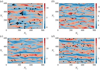
Next, we investigate particle distribution within near-wall turbulence, where shear forces are most significant. Near the wall, alternating low- and high-speed streaks dominate turbulent channel flow structures. Depending on their size, inertia and flow conditions (Peng et al. Reference Peng, Wang and Chen2024), particles often preferentially accumulate in either low-speed streaks (e.g. Niño & Garcia Reference Niño and Garcia1996; Kidanemariam et al. Reference Kidanemariam, Chan-Braun, Doychev and Uhlmann2013; Fong, Amili & Coletti Reference Fong, Amili and Coletti2019) or high-speed streaks (e.g. Do-Quang et al. Reference Do-Quang, Amberg, Brethouwer and Johansson2014; Eshghinejadfard et al. Reference Eshghinejadfard, Zhao and Thévenin2018; Zhu et al. Reference Zhu, Yu, Pan and Shao2020). Figure 6 presents snapshots of streamwise velocity distribution in an
 $x{-}z$
plane at
 $y^+ \approx 9$
, along with the projection of particles onto this plane. The results reveal that short cylinders (figure 6
a) preferentially accumulate in low-speed streaks, whereas the other three cases (figure 6
b–d) show preferential accumulation in high-speed streaks. The irregular projected shapes of unit and long cylinders further confirm that their axes are rarely perfectly aligned during particle–particle or particle–wall interactions, indicating that face–face contacts are scarce.
Snapshots of the particle distribution in near-wall streaks at the height of
 $y^+\approx 9$
: (a) PL-SC, (b) PL-UC, (c) PL-LC, (d) PL-S.

To quantify this preferential accumulation, we adopt the statistical approach of Kidanemariam et al. (Reference Kidanemariam, Chan-Braun, Doychev and Uhlmann2013) and Peng et al. (Reference Peng, Wang and Chen2024). We analyse the near-wall plane at
 $y^+ \approx 9$
, previously used by Kim, Moin & Moser (Reference Kim, Moin and Moser1987) and Marchioli & Soldati (Reference Marchioli and Soldati2002), for visualising near-wall streak structures. The methodology follows the steps outlined below.
First, compute the streamwise velocity averaged over the streamwise direction at each spanwise location:
 \begin{equation} U\left (y^+\approx 9,z,t\right ) = \left\langle u\left (x,y^+\approx 9,z,t\right )\right\rangle ^{x}. \end{equation}
Next, identify the location occupied by a particle in this plane and record the local streamwise velocity and the spanwise distance from the particle centre:
 \begin{equation} u_f\left (\Delta z = \vert z_p - z_f\vert \right ) = U\left (y^{+}\approx 9,z_f,t\right )\!. \end{equation}
Finally, compute the time- and particle-averaged velocity:
 \begin{equation} U_f^+(\Delta z^+) = \langle u_f\left (\Delta z\right )\rangle . \end{equation}
Figure 7 compares
 $U_f^+(\Delta z^+)$
across cases. Particles preferentially accumulating in low-speed streaks exhibit flow velocities lower than the plane average for small
 $\Delta z^+$
, while those accumulating in high-speed streaks show the opposite trend. The statistical evidence confirms the visualisation: short cylinders accumulate in low-speed streaks, whereas the other particle types favour high-speed streaks.
Conditionally averaged streamwise fluid velocity as a function of spanwise distance from the geometric centre of the cylindrical particle. The horizontal dashed line of the same colour represents the respective mean streamwise velocity at the same wall-normal location.

In a recent study we systematically examined the mechanisms governing particle accumulation in near-wall streaks (Peng et al. Reference Peng, Wang and Chen2024). In wall-bounded turbulence, near-wall flow structures are dominated by quasi-streamwise vortices. Particles entering the streak plane through strong sweeping events are further transported to low-speed streaks under the influence of these vortices (Niño & Garcia 1996). However, when particle sizes are comparable to those of the vortices, the vortices struggle to transport them into low-speed streaks. In the absence of significant settling effects, such large particles quickly escape the near-wall region either due to repulsion from particle–wall interactions or through strong ejection events before reaching low-speed streaks. Consequently, large non-settling particles are more frequently observed in high-speed streaks (Peng et al. Reference Peng, Wang and Chen2024).
The preferential accumulation of short cylinders in low-speed streaks can be explained by these mechanisms. As implied by figure 5 and later confirmed in figure 10, short cylinders tend to orient their symmetry axes along the wall-normal direction, maximising the strong attractive lubrication force that would retain them in the very near-wall region. Additionally, these cylinders remain very close to the channel walls, preventing the formation of strong ejection events underneath them. These factors enable short cylinders to reside in the near-wall region long enough to be transported to low-speed streaks.
In contrast, the other three cases lack these retention mechanisms, leading to particles leaving the near-wall region before reaching low-speed streaks and instead accumulating in high-speed streaks. This difference in preferential accumulation directly impacts the relative velocities of the particle and fluid phases around the streak plane (
 $y^+ \approx 9$
). In case PL-SC, the mean velocity of the particle phase lags behind that of the fluid phase, whereas in the other three cases, the particle phase moves faster than the surrounding fluid, as confirmed later in figure 9.
Mean velocity of the fluid and particle phases. Here
 $u_{\kern-1pt p}$
denotes the mean velocity of the particle phase and
 $u_{\kern-1pt f}$
denotes the mean velocity of the fluid phase.

The above observations pertain to neutrally buoyant particles. In real suspensions, density mismatch modifies particle inertia, which can in turn influence preferential accumulation. Point-particle simulations have shown that accumulation is highly sensitive to particle inertia (Zhao et al. Reference Zhao, Marchioli and Andersson2014; Marchioli et al. Reference Marchioli, Zhao and Andersson2016). For finite-size particles, however, the effect of density ratio appears primarily quantitative. For example, our recent work demonstrated that large particles (
 $d_p^+ \approx 30$
) with
 $\rho _p/\rho _f = 1.0$
, 2.5 and 7.8 all preferentially accumulated in high-speed streaks, although heavier particles exhibited a weaker concentration (Peng et al. Reference Peng, Wang and Chen2024).
Gravitational settling may also influence near-wall particle accumulation. In the same study (Peng et al. Reference Peng, Wang and Chen2024), we examined varying levels of settling, quantified by the Shields number
 $\varTheta = \rho _f u_\tau ^2/[g d_p (\rho _p - \rho _f)]$
. Three cases were considered:
 $\varTheta = \infty$
(no settling),
 $\varTheta = 0.907$
(weak settling) and
 $\varTheta = 0.2$
(strong settling). In all cases, large particles (
 $d_p^+ \approx 30$
) preferentially accumulated in high-speed streaks due to finite-size effects, but the accumulation intensity weakened with stronger settling. For finite-size particles whose diameters are much larger than the Kolmogorov scale, particle size often plays a more decisive role than other parameters in governing preferential accumulation. These findings suggest that while density ratio and settling intensity may modulate the strength of streak accumulation, the qualitative trends reported here are expected to remain robust.
To provide a more comprehensive overview of preferential accumulation, we compile observations reported in the literature and present them in figure 8. The results for spherical particles are drawn from the studies of Suzuki, Ikenoya & Kasagi (Reference Suzuki, Ikenoya and Kasagi2000), Marchioli & Soldati (Reference Marchioli and Soldati2002), Fong et al. (Reference Fong, Amili and Coletti2019), Zhu et al. (Reference Zhu, Yu, Pan and Shao2020), Berk & Coletti (Reference Berk and Coletti2023), Peng et al. (Reference Peng, Wang and Chen2024) and are represented by circles. Observations for spheroidal particles from Mortensen et al. (Reference Mortensen, Andersson, Gillissen and Boersma2008), Marchioli, Fantoni & Soldati (Reference Marchioli, Fantoni and Soldati2010), Zhao et al. (Reference Zhao, George, van and Berend2015a ), Eshghinejadfard et al. (Reference Eshghinejadfard, Zhao and Thévenin2018) are shown as ellipses, while those for cylindrical particles from Do-Quang et al. (Reference Do-Quang, Amberg, Brethouwer and Johansson2014), Shaik et al. (Reference Shaik, Kuperman, Rinsky and van Hout2020), Baker & Coletti (Reference Baker and Coletti2022) and the present study are depicted using rectangles. Filled symbols indicate cases where particles were observed to preferentially accumulate in low-speed streaks, while open symbols represent accumulation in high-speed streaks. It is important to note that only studies explicitly reporting the accumulation location were included. Studies in which the preferential accumulation is only implied – e.g. inferred from the mean velocity difference between the particle and fluid phases – were excluded from this summary.
A summary of how particles’ preferential locations depend on their aspect ratios and sizes, from the literature and this work.

Overall, the accumulation locations of spheroidal particles – including spheres and ellipsoids – depend strongly on their size: smaller particles tend to accumulate in low-speed streaks, while larger particles preferentially accumulate in high-speed streaks. This trend is primarily attributed to finite-size effects, as discussed earlier. Interestingly, cylindrical particles appear to accumulate in high-speed streaks at sizes where spherical particles instead accumulate in low-speed streaks. However, it is important to note that particle size here is characterised by the volumetric equivalent sphere diameter, which may not fully capture the influence of particle shape – especially for particles with extreme aspect ratios.
For large particles with
 $d_e^+ \gt 10$
, our simulation case PL-SC is the only reported case in which preferential accumulation occurs in low-speed streaks. In contrast, the experimental study by Baker & Coletti (Reference Baker and Coletti2022) found that very thin disks (
 $\lambda = 0.044$
) tend to accumulate in high-speed streaks. The experiments of Baker & Coletti were also conducted at a much higher
 $\textit{Re}_\tau = 620$
and included settling effects. However, the latter may have been minor, since the density ratio was purposely kept moderate (
 $\rho _p/\rho _f = 1.38$
for the disks). Our previous study on spherical particles showed that settling tends to reduce preferential accumulation in high-speed streaks rather than strengthen it, suggesting that settling alone cannot explain the discrepancy.
A possible explanation is that short cylinders in our simulations accumulate in low-speed streaks because they can stably reside very close to the wall for extended periods. This mechanism may be less pronounced at higher Reynolds numbers, where stronger turbulence generates more energetic ejection events that quickly repel particles from the near-wall region – effectively producing a ‘high-speed in, high-speed out’ scenario (Peng et al. Reference Peng, Wang and Chen2024). Furthermore, the aspect ratio of the particles in Baker & Coletti (Reference Baker and Coletti2022)’s work was an order of magnitude smaller than in our short-cylinder case, and this geometric difference could also play a role.
Given the limited number of available data points, it remains unclear whether this discrepancy indicates a second transition in the accumulation behaviour or arises from other factors – such as the potential inaccuracy of the lubrication force model used in our simulations or imprecise particle shapes in the experiments. Further investigation is needed to clarify this apparent inconsistency.
Figure 9 presents the mean velocity profiles of the fluid and particle phases across the channel. In the bulk flow region, the velocity differences between the two phases are negligible. However, within the viscous sublayer and buffer layer (
 $y^+ \lt 30$
), significant differences emerge. The particle-phase velocity in cases PL-UC, PL-LC and PL-S exceeds that of the fluid phase, whereas in PL-SC, the particle phase moves more slowly than the surrounding fluid. This trend aligns with the observed preferential accumulation of PL-SC particles in low-speed streaks and of particles in the other three cases in high-speed streaks.
It should be noted that in previous studies, the velocity deficit between the fluid and particle phases has often been attributed to the preferential sampling of particles in low- or high-speed streaks (e.g. Kidanemariam et al. Reference Kidanemariam, Chan-Braun, Doychev and Uhlmann2013; Shaik et al. Reference Shaik, Kuperman, Rinsky and van Hout2020). While this explanation may be reasonable for passive tracer particles, it does not fully apply to finite-size particles, which can significantly disturb the surrounding fluid. A simple counterexample is provided by laminar flows, where there are no streaks, yet finite-size particles still exhibit a velocity different from the fluid phase. This difference gives rise to the Segre–Silberberg effect and underpins the derivation of the Saffman lift force (Saffman Reference Saffman1965).
Furthermore, if the mean velocity deficit of particles were solely due to their over-representation in low-speed regions, their mean velocity should not fall below the characteristic velocity of those regions. However, this is not supported by our simulation results. For instance, figure 7 shows that the mean flow velocity around the particles (
 $\Delta z^+ \approx 0$
) is approximately
 $U^+ \approx 5.3$
in case PL-SC, and between 8 and 9 in the other three cases. These values can be interpreted as the representative fluid velocities of the low-speed streaks in PL-SC and the high-speed streaks in the other cases. Yet, as shown in figure 9, the mean particle velocity at
 $y^+ \approx 9$
is less than 5 in PL-SC and close to 10 in the other three cases – indicating that the particles move more slowly or quickly than even the surrounding fluid within the same streak type.
We therefore argue that the velocity deficit between the particle and fluid phases should not be viewed purely as a consequence of preferential sampling. Instead, differences in particle mobility and orientation can independently lead to discrepancies between particle and fluid velocities. These velocity differences, in turn, may contribute to preferential accumulation – for example, slowly moving particles may remain more stable within low-speed regions. That said, we do not suggest that preferential sampling plays no role in the observed velocity deficits, rather that the particle–fluid system forms a tightly coupled and nonlinear system in which both mechanisms may be intertwined.
The sudden jump observed in the mean velocity profile of the particle phase in case PL-SC at
 $y^+\approx 15$
originates from a discontinuity in the wall-normal distribution of short cylinders at approximately the same location, as evidenced by the sharp drop in the corresponding particle volume fraction profile shown in figure 5. The short cylinders have a length of
 $L^+ = 15.17$
, which closely matches the location of the velocity discontinuity. Below this height, the particle-phase velocity is predominantly influenced by short cylinders oriented in the wall-normal direction, forming an accumulation layer near the wall. Above this point, the particle-phase velocity reflects the dynamics of particles whose centres are located farther from the wall. This abrupt shift in the contributing particle population leads to a discontinuity in the velocity profile. For unit cylinders, long cylinders and spherical particles, the particle-phase velocity in the near-wall region is governed by a more consistent group of particles that are less aligned with the wall-normal direction. Nevertheless, because the particle volume fraction remains nearly zero immediately above the wall, the particle-phase velocity profiles in these cases still exhibit a noticeable, albeit less pronounced, jump near the wall.
3.1.3. Particle orientation and rotation
Due to anisotropy in both the shape and the distribution of kinetic energy, cylindrical particles exhibit preferential orientation in a turbulent channel flow. Previous studies (e.g. Marchioli et al. Reference Marchioli, Fantoni and Soldati2010; Challabotla et al. Reference Challabotla, Zhao and Andersson2015a
; Ardekani et al. Reference Ardekani, Costa, Breugem, Picano and Brandt2017; Eshghinejadfard et al. Reference Eshghinejadfard, Zhao and Thévenin2018) have examined this phenomenon by computing the average cosine values of the angles between the particle rotational axes and the inertial coordinate system. In this study we take an alternative approach by analysing the probability distribution functions (PDFs) of the angles between the cylinder axis and the streamwise (
 $\phi$
) and wall-normal (
 $\theta$
) directions, i.e.
 \begin{equation} \phi = \arccos ({\boldsymbol z^{\prime}}\boldsymbol{\cdot }{\boldsymbol e}_x),\,\,\,\,\theta = \arccos ({\boldsymbol z}^{\prime} \boldsymbol{\cdot }{\boldsymbol e}_y) \end{equation}
where
 ${\boldsymbol z}^{\prime}$
is the orientation vector of the cylinder defined in (2.5), and
 ${\boldsymbol e}_x = (1,0,0)$
and
 ${\boldsymbol e}_{y} = (0,1,0)$
are the unit vectors aligned with the streamwise and wall-normal directions, respectively. Since the turbulent channel flow is inhomogeneous in the wall-normal direction, cylinder orientation statistics may vary across different regions of the flow. To capture this effect, we divide the channel into three sections: the near-wall region (
 $y^+ \leqslant 20$
), the mid-range region (
 $20 \lt y^+ \leqslant 50$
) and the centre region (
 $y^+ \gt 50$
). Given the relatively large size of the particles in this study compared with the wall unit, it is challenging to categorise the flow strictly into the typical viscous sublayer, buffer region and logarithmic region.
Probability distribution functions of the cylinder axis orientation angles: (a) overall PDF of particle orientation in the whole channel, (b) PDF in the near-wall region
 $y^{+} \leqslant 20$
, (c) PDF in the mid-range region
 $20\lt y^{+} \leqslant 50$
, and (d) PDF in the channel centre region
 $y^{+} \gt 50$
. The total sample numbers are
 $1.03\times 10^7$
,
 $1.03\times 10^7$
and
 $1.09\times 10^7$
for cases PL-SC, PL-UC and PL-LC, respectively.

Figure 10 shows the global PDFs of the orientation angles
 $\phi$
and
 $\theta$
, aggregating all samples, along with regional PDFs for particles located in the near-wall, mid-range and centre regions. The distribution of particle samples across these regions is as follows: 7.9 %, 19.9 % and 72.2 % for PL-SC; 6.9 %, 21.4 % and 71.7 % for PL-UC; and 5.2 %, 22.0 % and 72.8 % for PL-LC, respectively. The black line represents the expected PDF for a randomly oriented vector in an inertial frame and serves as a reference to evaluate the degree of preferential orientation. Under the assumption that the orientation vector terminates on a hemisphere of radius
 $R$
, the PDF of the angle
 $\theta$
(or
 $\phi$
) between this vector and an inertial axis is
 $\sin \theta$
(or
 $\sin \phi$
).
Near the wall (figure 10
b), most short cylinders align their axes along the wall-normal direction (
 $\theta = 0$
and
 $\phi = 90^\circ$
). This behaviour is consistent with the observations of Ardekani et al. (Reference Ardekani, Costa, Breugem, Picano and Brandt2017) for oblate spheroids and can be explained by the Jeffery orbits of disk-shaped particles in simple shear flows (Voth Reference Voth2015). In the high-shear region near the channel walls, oblate particles tend to spend more time with their symmetry axis aligned with the velocity gradient direction before undergoing a tumbling event, leading to a statistical preference for wall-normal alignment (Voth Reference Voth2015). The observed alignment of short cylinders with the wall-normal direction also agrees with the findings of Challabotla et al. (Reference Challabotla, Zhao and Andersson2015a
) for non-inertial, sub-Kolmogorov-scale oblate tracer particles.
When aggregating all wall-normal regions, unit cylinders exhibit an orientation that is nearly random. Near the wall, they show a slight preference for aligning parallel to the wall (
 $\phi = 0$
); however, their precise in-plane orientation in the
 $x{-}z$
plane remains largely random, with slight preferences in either the streamwise or spanwise location. This weak preferential alignment persists into the mid-range but disappears at the channel centre, where the PDFs of both
 $\theta$
and
 $\phi$
closely follow those of a randomly oriented vector.
As the particle aspect ratio increases further, long cylinders demonstrate a clear tendency to align their main axes with the streamwise direction across the entire channel height. Similar preferential alignment of small inertial fibres (modelled as prolate spheroids) in turbulent channel flows has been reported in earlier studies (Zhang et al. Reference Zhang, Ahmadi, Fan and McLaughlin2001; Mortensen et al. Reference Mortensen, Andersson, Gillissen and Boersma2008; Marchioli et al. Reference Marchioli, Fantoni and Soldati2010, Reference Marchioli, Zhao and Andersson2016). Notably, these studies span a wide range of particle-to-fluid density ratios – from unity in the present work to values as large as
 $O(10^3)$
in earlier investigations – and yet all consistently document the same trend of streamwise alignment. While the degree of alignment is influenced by particle aspect ratio and inertia, the qualitative behaviour appears robust across density ratios. This universality likely reflects the fundamental preference of elongated particles to align with the local vorticity. In near-wall turbulence, vorticity is predominantly streamwise, favouring alignment in that direction. By contrast, orientations in the wall-normal or spanwise directions expose fibres to strong mean shear and spanwise velocity gradients associated with low- and high-speed streaks, which induce tumbling and reorientation, thereby reinforcing the streamwise preference.
In addition, previous studies have reported a local preference for wall-normal alignment of prolate spheroids very close to the wall (see, e.g. figure 4a in Marchioli et al. Reference Marchioli, Zhao and Andersson2016), which is consistent with our observation of a secondary peak in the PDF at
 $\theta \approx 0$
for near-wall particles (figure 10
b). This tendency is likely driven by the strong shear and coherent near-wall structures such as ejection and sweep events. These flow features induce rotation about the spanwise axis, causing particles that are initially aligned in the streamwise direction to flip toward a wall-normal orientation.
Overall, our observations of the orientation behaviour of cylindrical particles with sharp edges align well with earlier findings for non-spherical spheroids. Short, disk-like cylinders tend to align in the wall-normal direction, while long, rod-like cylinders preferentially align with the streamwise direction. Unit cylinders exhibit only weak orientation preferences, with their distribution approaching randomness. The strongest preferential orientations are consistently observed near the wall, where shear is most intense, and gradually diminish toward the channel centre, where turbulence becomes more isotropic and homogeneous.
While it is tempting to draw a direct equivalence between cylinders and spheroids, especially at large aspect ratios where sharp-edge effects might seem negligible, the situation is more subtle. Cox (Reference Cox1970) derived leading-order asymptotics for the drag in uniform flow aligned with or perpendicular to the axis in the Stokes limit. Cox’s results show that the difference between a flat-ended cylinder and a spheroid enters only through geometry-dependent constants, whose relative influence diminishes as the aspect ratio increases. However, in terms of rotational dynamics, Bretherton (Reference Bretherton1962) demonstrated that any axisymmetric body can be described by Jeffery’s equations (see Jeffery Reference Jeffery1922b
) provided the geometric aspect ratio
 $\lambda$
is replaced with an effective aspect ratio
 $r_e$
. Extending this, Cox (Reference Cox1971) derived explicit slender-body asymptotics and showed that even as
 $\lambda \rightarrow \infty$
, the effective aspect ratios of cylinders and spheroids remain distinct. This persistent difference stems not only from sharp edges but also from fundamental geometric contrasts – for example, a cylinder has a constant cross-section along its length, whereas a spheroid tapers smoothly to points. In summary, while long cylinders may show qualitatively similar orientation statistics to spheroids, a strict Jeffery-type equivalence is not attainable. Establishing such an equivalence would require simpler flows and much larger aspect ratios than those considered in the present simulations.
To better understand how the particle rotation statistics and its orientation statistics are coupled, we compare the rotational behaviour of cylinders across different cases. The rotation of cylindrical particles exhibits anisotropy and can be decomposed into two modes: spinning (rotation around its axis, the
 $z^{\prime}$
axis) and tumbling (rotation around the
 $x^{\prime}$
or
 $y^{\prime}$
axes). The moments of inertia associated with these rotational axes are given by
 \begin{align} J_{r'}=J_{x'}=J_{y'}&=\frac {m}{48}(3D^2+4L^2), \end{align}
 \begin{align} J_{z'}&=\frac {m}{8}D^2, \end{align}
where
 $J_{r'}$
represents the moment of inertia for tumbling,
 $J_{z'}$
corresponds to the moment of inertia for spinning and
 $m$
is the particle mass. The computed values of
 $J_{r'}$
and
 $J_{z'}$
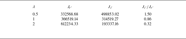
for the three cylinder shapes examined in this study are listed in table 2. Notably, for unit and long cylinders, the moment of inertia for spinning is smaller than that for tumbling, whereas for short cylinders, the opposite holds true.
The moment of inertia of tumbling and spinning for different aspect-ratio cylinders. Here
 $J_{r'}$
corresponds to tumbling and
 $J_{z'}$
corresponds to spinning. The density
 $\rho$
of all particles is 1 and the length unit is scaled with
 $\Delta x$
.

Distribution of angular velocities along the wall-normal direction. The angular velocities are normalised by
 $u_\tau ^2/\nu$
. The tumbling rates
 $\varOmega _t$
are denoted as solid lines and the spinning rates
 $\varOmega _s$
are denoted as dashed lines.

Figure 11 presents the distribution of the averaged tumbling and spinning angular velocities of particles along the wall-normal direction for each case. The tumbling angular velocity is defined as
 \begin{align} \varOmega _t=\sqrt {0.5\left (\varOmega ^2_{x'}+\varOmega ^2_{y'}\right )} \end{align}
and the spinning angular velocity
 $\varOmega _s$
is simply
 $\varOmega _{z'}$
. The wall-normal domain is divided into 20 equal bins, and the tumbling and spinning angular velocities are statistically averaged over all particle samples whose centres fall within each bin.
Across all three cylinder types, both tumbling and spinning rates are highest near the channel wall and decrease with increasing wall-normal distance due to the diminishing shear. Among them, unit cylinders (PL-UC) exhibit the highest near-wall tumbling rates, while the maximum tumbling rates of short and long cylinders are comparable. The relatively stable wall-normal alignment of short cylinders imposes stronger geometric constraints from the channel wall, whereas unit cylinders, with less restrictive alignment, experience fewer hindrances during tumbling.
In contrast, both unit and long cylinders preferentially align with the streamwise direction, although the alignment is weaker for unit cylinders. Long cylinders exhibit a stronger alignment tendency due to their geometry. Since the near-wall region is dominated by quasi-streamwise vortices, cylinders aligned with these structures experience less rotational disturbance and are therefore less prone to tumbling. Moreover, unit cylinders not only orient more frequently toward the wall-normal and spanwise directions than long cylinders, but also possess a smaller moment of inertia for rotation, making them more susceptible to tumbling. These two factors collectively contribute to the lower tumbling rates observed for long cylinders compared with unit cylinders.
Spinning rates for unit and long cylinders are significantly higher than those for short cylinders. This is due not only to the fact that short cylinders possess the largest moment of inertia for spinning, but also because their wall-normal alignment right above the wall inhibits spinning: the torque required for spinning originates from shear in the spanwise direction, which is weak near the wall. Although the near-wall region of a turbulent channel flow features alternating low- and high-speed streaks in the spanwise direction, these structures arise from ejection and sweep events generated by quasi-streamwise vortices. These events promote tumbling rather than spinning of wall-normal aligned particles. In contrast, streamwise-aligned unit and long cylinders are more readily spun by the same vortices. While the moment of inertia for spinning,
 $J_{z'}$
is smaller for long cylinders than for unit cylinders, the wall-unit diameter of long cylinders is
 $D^+ \approx 19$
, compared with
 $D^+ \approx 24$
for unit cylinders, the latter being closer to the typical diameter of a streamwise vortex (Kim et al. Reference Kim, Moin and Moser1987; Peng et al. Reference Peng, Wang and Chen2024). This proximity may partially explain the nearly identical spinning rates observed for unit and long cylinders. That is, unit cylinders appear to experience stronger driving torque from streamwise vortices, which enhances their spinning behaviour.
Throughout the channel, long cylinders consistently show lower tumbling and higher spinning rates – consistent with previous interface-resolved DNS (Zhu et al. Reference Zhu, Yu and Shao2018) and point-particle simulations (Zhao et al. Reference Zhao, Challabotla, Andersson and Variano2015b
) of prolate spheroids. In contrast, the opposite trend is observed for short cylinders. For unit cylinders, spinning exceeds tumbling near the wall, but the reverse is true in the mid-range wall-normal region. For
 $y^+ \gt 100$
, tumbling and spinning rates become nearly equal, with spinning being slightly higher. This behaviour reflects the increasingly homogeneous and isotropic turbulence toward the channel centre, where the orientation of unit cylinders approaches randomness (see figure 10). The slightly elevated spinning rate may be attributed to the marginally smaller moment of inertia associated with spinning compared with tumbling.
To better summarise the above analysis, we illustrate the main mechanisms influencing the orientation and rotation of cylindrical particles in figure 12. These mechanisms rely on the fact that near-wall coherent structures are not entirely altered by the presence of particles, as evidenced by the persistence of streaks and quasi-streamwise vortices (figure 6). Near the wall, short cylinders are readily flipped by the strong shear and tend to align in the wall-normal direction, whereas longer cylinders, with smaller projected frontal areas, are more resistant to flipping and tend to maintain a streamwise orientation. Because the near-wall region is dominated by quasi-streamwise vortices, streamwise-aligned cylinders are more likely to spin than tumble, while wall-normal-oriented short cylinders are more prone to tumbling. However, the tumbling motion of short cylinders is also constrained by their stable positioning very close to the wall. As the distance from the wall increases and the turbulence becomes more homogeneous and isotropic, particle orientations become more random. Nevertheless, weak preferences persist – short cylinders slightly favour wall-normal orientations, while long cylinders tend to align streamwise. As a result of these orientation tendencies and differences in moment of inertia, long cylinders consistently exhibit higher spinning rates than tumbling, while short cylinders show the opposite behaviour.
Sketch of the main mechanisms that affect the orientation and rotation statistics of the three types of cylindrical particles (from left to right – LC, UC, SC) in different regions of the channel (top row – channel centre; bottom row – near channel wall).

While the above summary is based on our simulations with neutrally buoyant particles, previous studies indicate that the influence of density ratio on the dynamics of finite-size particles is less decisive than for point particles. For instance, our recent work on the settling of finite-size particles in homogeneous isotropic turbulence showed that, although velocity fluctuations decreased with increasing inertia, the mean slip velocity – and, thus, the effective drag – was only weakly affected, as the surrounding flow was substantially modified by the particle itself (Peng et al. Reference Peng, Karzhaubayev, Wang, Chen and Niu2025). These results suggest that the main particle-motion trends reported here are qualitatively robust with respect to density ratio, even though quantitative differences may arise.
3.2. Flow modulation by cylinders
We now examine how cylindrical particles with different aspect ratios influence flow statistics in the turbulent channel. Figure 13(a) shows the mean velocity profiles of the fluid phase for various particle-laden cases, while figure 13(b) displays the relative modulation of fluid velocity compared with the unladen single-phase case. For reference, the mean velocity profile from a turbulence case laden with oblate spheroids (
 $\lambda =1/3$
and
 $\phi _p = 0.05$
) reported in Eshghinejadfard et al. (Reference Eshghinejadfard, Zhao and Thévenin2018) is also included in figure 13(a). Under the current simulation parameters, the fluid mean velocity profiles for the unit (
 $\lambda = 1$
, PL-UC) and long (
 $\lambda = 2$
, PL-LC) cylinders are similar and exhibit a slight reduction compared with the single-phase case. In contrast, the velocity profile for the short cylinders (
 $\lambda =1/2$
, PL-SC) shows a significantly larger reduction, indicating a stronger modulation effect on the mean flow.
Profiles of the mean velocity distribution: (a) mean velocity profiles, (b) modulation from the single-phase case
 $\Delta U^+ = U_{pl}^{+} - U_{sp}^+$
. Here ‘SP’ denotes single-phase turbulence and ‘E2018’ denotes the case of
 $\lambda =1/3$
oblate spheroids in Eshghinejadfard et al. (Reference Eshghinejadfard, Zhao and Thévenin2018).

Unlike spherical particles, which tend to enhance fluid velocity in the viscous sublayer (
 $y^+\leqslant 5$
), the modulation induced by unit and long cylinders in this region is negligible. This weaker modulation can be attributed to their lower particle volume fractions in the viscous sublayer, as shown in figure 5. Previous studies (e.g. Peng et al. Reference Peng, Ayala and Wang2019) have shown that particles near the wall do not necessarily obey the no-slip condition. If these particles move faster than the surrounding fluid, they can accelerate the flow and increase the mean velocity relative to the single-phase case. As shown earlier in figure 7, the fluid velocity near particles in cases PL-UC, PL-LC and PL-SC is approximately
 $U_f^+ \approx 8$
, while the corresponding particle velocities near the wall are around
 $U_p^+ \approx 10$
, according to figure 9. These results indicate that particles in these cases move faster than the local fluid phase near the wall. However, in PL-UC and PL-LC, the low particle volume fractions result in only a weak acceleration effect. In contrast, PL-SC exhibits the highest particle volume fraction near the wall, but in this case, the particle velocity is actually lower than the fluid velocity (
 $U_f^+\approx 5$
,
 $U_p^+ \approx 3$
). As a result, short cylinders induce the most significant reduction in fluid velocity in the near-wall region.
Beyond the viscous sublayer, cylindrical particles reduce the fluid velocity, similar to the behaviour observed for spherical particles in both the present study and previous investigations (e.g. Picano et al. Reference Picano, Breugem and Brandt2015; Eshghinejadfard et al. Reference Eshghinejadfard, Abdelsamie, Hosseini and Thévenin2017). Among all cases, the most pronounced velocity reduction occurs in PL-SC, which contains short cylinders. In all particle-laden cases, the maximum reduction in fluid velocity is observed near the upper edge of the buffer region (
 $y^+\approx 30$
). As analysed in our previous study (Peng et al. Reference Peng, Ayala and Wang2019), this reduction is likely due to particles interfering with strong momentum transport between the inner and outer fluids in the near-wall region. However, beyond the buffer region (
 $y^+\geqslant 30$
), where fluid shear weakens, the presence of solid particles enhances wall-normal momentum transport, partially mitigating the overall velocity reduction. The results from the three cylindrical particle cases suggest that the mean velocity reduction decreases with increasing particle aspect ratio – that is, short cylinders exert the strongest modulation. Notably, although the oblate spheroids studied by Eshghinejadfard et al. (Reference Eshghinejadfard, Zhao and Thévenin2018) have an even smaller aspect ratio
 $\lambda = 1/3$
than the short cylinders in PL-SC, the modulation they induce is weaker. This suggests that sharp-edged cylindrical particles generate stronger flow modifications than smooth spheroidal particles of similar geometry and volume fraction.
Table 3 summarises the mean streamwise velocities averaged across the channel for different cases. All particle-laden turbulence cases exhibit lower mean velocities than the single-phase flow. Among them, spherical particles cause the smallest reduction in flow velocity, as their velocity-enhancing effect near the wall partially counteracts the velocity reduction in the buffer region. In contrast, short cylinders induce the most significant velocity reduction, exceeding 18 %, while other particle shapes reduce the velocity by less than 10 %.
Modulation of the mean flow velocity.

Profiles of the Reynolds stress distribution.

The wall-normal distributions of Reynolds stress for each case are plotted in figure 14, along with data from Eshghinejadfard et al. (Reference Eshghinejadfard, Zhao and Thévenin2018) (E2018) and Ardekani & Brandt (Reference Ardekani and Brandt2019) (A2019). The latter study simulated turbulence in a channel laden with prolate spheroidal particles of aspect ratio 3 at a viscous Reynolds number of 180 and a solid volume fraction of 10 %. In these simulations, the authors reported that oblate spheroids increased turbulent drag by 1.2 % (E2018), while prolate spheroids reduced it by 0.89 % (A2019).
Outside the viscous sublayer, spherical particles tend to enhance the Reynolds stress, whereas non-spherical particles generally suppress it. For cylindrical particles, the attenuation of Reynolds stress becomes more pronounced as the particle shape becomes more disk-like. Previous studies have shown that spheroidal particles can reduce the Reynolds stress while simultaneously increase the overall velocity gradient, resulting in a higher mean flow velocity in particle-laden flows compared with the single-phase case (e.g. Eshghinejadfard et al. Reference Eshghinejadfard, Zhao and Thévenin2018; Zhu et al. Reference Zhu, Yu and Shao2018; Ardekani & Brandt Reference Ardekani and Brandt2019). In contrast, the present study finds that although cylindrical particles reduce the Reynolds stress, they also diminish the mean velocity gradient throughout the channel, leading to a lower mean flow velocity compared with the single-phase case, as shown in table 3.
In a single-phase turbulent channel flow, the driving force is balanced by two opposing mechanisms: viscous stress arising from the mean velocity gradient and Reynolds stress generated by turbulent fluid motion. With the addition of particles, not only are these intrinsic mechanisms modified, but two additional particle-induced mechanisms are introduced. The first is the particle-phase analogue of viscous stress, stemming from the gradient in the mean particle velocity across the channel height – slower near the wall and faster near the centre, as shown in figure 9. The second is the stress-like contribution from particle velocity fluctuations. To help readers better understand these mechanisms, we qualitatively sketch them in figure 15. Some previous studies have formulated these effects mathematically through a stress balance analysis of the fluid–particle mixture (e.g. Picano et al. Reference Picano, Breugem and Brandt2015; Yu et al. Reference Yu, Lin, Shao and Wang2017). However, this formulation relies on a vaguely defined ‘particle inner stress’ (the counterpart to fluid viscous stress), which often must be inferred from the balance rather than computed directly.
Sketch of the counter mechanisms to the driving force in a cylinder particle-laden turbulent channel flow.

Assuming the total driving force remains unchanged, whether the overall flow stress is enhanced or reduced depends on the relative strength of these modifications. If the suppression of turbulent fluid fluctuations is stronger than the combined contribution of the two particle-induced mechanisms, the result is an increased mean velocity gradient and, thus, a higher mean flow velocity. Conversely, if a larger portion of the driving force is required to balance the additional stresses introduced by the particles – exceeding the suppression of Reynolds stress – then a reduced mean velocity is observed. A plausible explanation for this outcome lies in particle geometry. Unlike spheroidal particles with smooth surfaces, cylindrical particles have sharp edges and flat ends, which likely increase the extent of disturbance flows (i.e. viscous boundary layer and wake) and as such the resistance to streamwise motion. These geometric features enhance the demand on the driving force to sustain both the mean and fluctuating motion of the particles, thereby altering the overall momentum transport efficiency and suppressing the mean velocity.
To provide a more comprehensive understanding of how finite-size particles with different shapes modulate the flow stress, we compile results reported in the literature and plot them as a function of aspect ratio in figure 16. In addition to the present study, the data are taken from recent fully resolved simulations by Ardekani et al. (Reference Ardekani, Costa, Breugem, Picano and Brandt2017), Zhu et al. (Reference Zhu, Yu and Shao2018), Eshghinejadfard et al. (Reference Eshghinejadfard, Zhao and Thévenin2018), Ardekani & Brandt (Reference Ardekani and Brandt2019). As before, circles denote spherical particles, ellipses indicate spheroids and rectangles represent cylinders with sharp edges. The particle volume fraction, which directly influences flow stress, is distinguished by the symbol size.
Summary of flow stress modulation in recent interface-resolved studies of particle-laden turbulent flows. Open symbols indicate cases reporting drag enhancement, while filled symbols indicate cases with drag reduction.

Two approaches are commonly adopted in the literature to set up comparative cases. One maintains a constant flow rate between the single-phase and particle-laden cases (e.g. Ardekani et al. Reference Ardekani, Costa, Breugem, Picano and Brandt2017; Ardekani & Brandt Reference Ardekani and Brandt2019), while the other keeps the driving force unchanged, as in the present study and some other previous investigations (e.g. Eshghinejadfard et al. Reference Eshghinejadfard, Zhao and Thévenin2018; Zhu et al. Reference Zhu, Yu and Shao2018). For the constant-flux cases, the ratio of wall stresses between the particle-laden and single-phase flows is given by
 \begin{equation} \frac {\tau _{w,\textit{PL}}}{\tau _{w,\textit{SP}}} = \left (\frac {u_{\tau ,\textit{PL}}}{u_{\tau ,\textit{SP}}}\right )^2 = \left (\frac {\textit{Re}_{\tau ,\textit{PL}}}{\textit{Re}_{\tau ,\textit{SP}}}\right )^2=\left (\frac {u_{\tau ,PL}/U_{\textit{PL}}}{u_{\tau ,SP}/U_{\textit{SP}}}\right )^2 = \left (\frac {U_{\textit{SP}}^+}{U_{\textit{PL}}^+}\right )^2, \end{equation}
assuming the same bulk flow rate (
 $U_{\textit{PL}} = U_{\textit{SP}}$
). This measure can also be approximately extended to constant-driving force cases, since a reduction in mean flow velocity implies drag enhancement and an increase implies drag reduction.
As shown in figure 16, for spheroidal particles – including both spheres and ellipsoids – drag enhancement is more frequently observed near unity aspect ratios, while drag reduction tends to occur at either low or high aspect ratios. In contrast, for cylindrical particles, the available data are relatively limited, and all reported cases exhibit drag enhancement. However, the degree of enhancement diminishes markedly with increasing aspect ratio. This trend further highlights the role of sharp edges and flat ends in enhancing drag for cylindrical particles.
To further understand how the aspect ratio of cylindrical particles influences the Reynolds stress, a quadrant analysis is conducted, and the Reynolds stress contributions from each quadrant are presented in figure 17. In the near-wall region (
 $y^+ \lesssim 15$
), particles of all shapes amplify the magnitudes of Reynolds stress components in all four quadrants, with relatively greater enhancements observed in the first (Q1) and third (Q3) quadrants. Among the various particle types, spherical particles generally induce the strongest enhancement – except in Q3, where short cylinders exhibit the most pronounced modulation. The third quadrant corresponds to low-speed fluid parcels moving toward the channel wall, an event that is relatively rare in single-phase turbulent channel flows. The notable enhancement of Q3 events in the short-cylinder case is likely due to disturbances caused by slowly moving, wall-normal-oriented short cylinders. As shown earlier in figure 9, except for the region immediately adjacent to the wall, short cylinders consistently move more slowly than the surrounding fluid. As faster fluid parcels overtake these particles, they may be decelerated and redirected toward the wall, thereby enhancing the occurrence and intensity of Q3 events.
Profiles of the Reynolds stress contribution from each quadrant. (a) The first quadrant Q1 (
 $u'\gt 0, v'\gt 0$
). (b) The second quadrant Q2 (
 $u'\lt 0, v'\gt 0$
). (c) The third quadrant Q3 (
 $u'\lt 0, v'\lt 0$
). (d) The fourth quadrant Q4 (
 $u'\gt 0, v'\lt 0$
).

Around the Reynolds stress peak (
 $20 \leqslant y^+ \leqslant 50$
), all particle-laden cases suppress Q2 (ejection) events while enhancing Q4 (sweep) events. The suppression of ejections is strongest for short cylinders and weakest for spherical particles, whereas the enhancement of sweeps is most pronounced for spheres, followed by short, unit and long cylinders. As established in classical single-phase wall turbulence (Kim et al. Reference Kim, Moin and Moser1987), the distribution of streamwise velocity fluctuations in this region is negatively skewed: ejection events (
 $u' \lt 0$
) are less frequent but more intense, while sweep events (
 $u' \gt 0$
) are more frequent but weaker. Because larger turbulent scales are generally more energetic than smaller ones, ejections can be loosely associated with energetic large-scale motions carrying fluid away from the wall, whereas sweeps are more closely linked to smaller-scale motions transporting fluid toward the wall. Finite-size particles preferentially damp turbulent structures larger than their own size while generating smaller-scale disturbances (Ten Cate et al. Reference Ten Cate, Derksen, Portela and Van Den Akker2004; Gao, Li & Wang Reference Gao, Li and Wang2013). As a result, they attenuate the less frequent but stronger large-scale ejections while promoting the more frequent sweep activity. Beyond
 $y^+ \gtrsim 90$
, spherical particles systematically increase Reynolds stress contributions across all quadrants, whereas cylindrical particles exert only minor influence.
The root-mean-square (r.m.s.) velocity profiles of the fluid phase in the streamwise, wall-normal and spanwise directions are presented in figure 18, along with results from Eshghinejadfard et al. (Reference Eshghinejadfard, Zhao and Thévenin2018) (aspect ratio
 $\lambda = 1/3$
,
 $\phi _p = 5\,\%$
) and Ardekani & Brandt (Reference Ardekani and Brandt2019) (
 $\lambda = 3$
,
 $\phi _p = 10\,\%$
). In all cases, the presence of particles leads to a reduction in the peak streamwise turbulence intensity around
 $y^+ \approx 15$
. Notably, in case PL-SC, a sudden change in particle volume fraction occurs near the same wall-normal location, resulting in a noticeable discontinuity in the distribution of the streamwise r.m.s. velocity. A similar reduction in the streamwise r.m.s. peak was observed by Shao, Wu & Yu (Reference Shao, Wu and Yu2012) for spherical particles, where it was attributed to the disruption of large-scale streamwise vortices by the particles. This disruption promotes a redistribution of turbulent kinetic energy into the wall-normal and spanwise velocity components, as seen in figures 18(b) and 18(c). Moreover, particles attenuate the local velocity gradient and Reynolds stress, thereby suppressing turbulent kinetic energy production in the streamwise component – further contributing to the observed reduction in its r.m.s. peak.
Profiles of the r.m.s velocity in the (a) streamwise direction; (b) wall-normal direction; (c) spanwise direction; (d) relative modulation on the r.m.s. velocity by spherical and cylindrical particles. Solid lines:
 $u^{\prime}_x$
; dashed lines:
 $u^{\prime}_y$
; dash-dot-dot lines:
 $u^{\prime}_z$
.

In the near-wall region (
 $y^+ \lesssim 30$
), cylindrical particles significantly enhance the r.m.s. velocities in both the wall-normal and spanwise directions. Among the three shapes considered, short cylinders induce the strongest enhancement, while unit and long cylinders produce nearly identical effects. These elevated velocity fluctuations are driven by particle-induced disturbances close to the wall. As shown in figure 9, particles near the wall often have substantial velocity differences relative to the surrounding fluid and preferentially accumulate within near-wall streaks (see figure 7). These interactions enhance local spatial inhomogeneity, thereby increasing turbulence intensity. Compared with streamwise-oriented unit and long cylinders, the wall-normal-oriented short cylinders exert a more pronounced disturbance due to both their larger effective cross-sectional area opposing the mean flow – as implied by the flow structures in figure 6 – and their higher volume fractions. A comparison between our PL-SC case and the E2018 case with oblate spheroids (aspect ratio
 $\lambda = 1/2$
vs.
 $1/3$
), as well as between PL-LC and A2019 (particle volume fraction 5 % vs 10 %), confirms that cylindrical particles with sharp edges induce significantly stronger turbulence modulation than smooth spheroidal particles.
Beyond the buffer layer (
 $y^+ \gtrsim 30$
), cylindrical particles slightly enhance the streamwise r.m.s. velocity but reduce those in the wall-normal and spanwise directions. This modulation is consistent with previous observations for spheroidal particles (E2018 and A2019) but differs from the behaviour of spherical particles, which tend to enhance velocity fluctuations in all three directions.
The wall-normal distribution of vorticity fluctuations in all three directions is shown in figure 19, with the fluctuations normalised by
 $u_\tau ^2/\nu$
. In the near-wall region, vorticity fluctuations exhibit strong anisotropy: the spanwise component
 $\langle \omega _z'\rangle$
dominates (as it is associated with the non-zero mean velocity gradient), followed by the streamwise component, with the wall-normal component being the weakest. Except in a narrow region very close to the wall (
 $y^+\lesssim 3$
), particles generally enhance the vorticity fluctuations in the streamwise and wall-normal directions more than in the spanwise direction, resulting in a more isotropic vorticity field.
Root mean square of vorticity components in the (a) streamwise direction; (b) wall-normal direction; (c) spanwise direction; (d) relative modulation by spherical and cylindrical particles. Solid lines:
 $\omega ^{\prime}_x$
; dashed lines:
 $\omega ^{\prime}_y$
; dash-dot-dot lines:
 $\omega ^{\prime}_z$
.

The enhancement of streamwise vorticity fluctuations can be understood by considering the nature of near-wall turbulent structures. In single-phase flow, the near-wall region is dominated by quasi-streamwise vortices. Particles located in this region can disrupt these large-scale vortices, especially enhancing streamwise vorticity fluctuations. Among the three cylindrical cases, the wall-normal-oriented short cylinders are expected to induce the strongest disruption due to their larger projected frontal area and perpendicular alignment relative to the mean flow, in contrast to the streamwise-oriented unit and long cylinders.
Additionally, particles near the wall often move at velocities significantly different from those of the surrounding fluid. This velocity mismatch causes the fluid to flow around the particles, generating local vorticity. The sharp edges of cylindrical particles further intensify these disturbances, leading to stronger vorticity fluctuations compared with smoother spheroidal particles, such as those used in E2018. Notably, the abrupt increases in vorticity fluctuations observed in case PL-SC around
 $y^+ \approx 15$
coincide with the length of the short cylinder (
 $L^+ = 15.17$
), suggesting that these spikes are associated with the edge of a wall-normal-oriented cylinder resting just above the wall. However, it is also observed that spherical particles tend to induce even greater vorticity modulation near the wall (see figure 19), which may be attributed to their higher local volume fraction, except in the region very close to the wall (
 $y^+\lesssim 10$
).
Although particles can locally disturb the flow and enhance spanwise vorticity fluctuations, they also tend to suppress the mean velocity gradient, which can reduce spanwise vorticity fluctuations. In turbulent channel flow, the spanwise r.m.s. vorticity is strongly correlated with the mean velocity gradient; both decrease monotonically toward the channel centre. Therefore, the net effect of particles on spanwise r.m.s. vorticity depends on the balance between these two competing mechanisms: enhancement due to local disturbances and suppression due to reduced mean shear.
Among the cases studied, spherical particles – which enhance the mean velocity gradient in the viscous sublayer – lead to the most significant increase in spanwise r.m.s. vorticity. This is followed by the unit and long cylinders. In contrast, short cylinders, which induce the greatest reduction in the near-wall mean velocity gradient, generally cause the most substantial decrease in spanwise r.m.s. vorticity, despite likely introducing the strongest local disturbances.
Finally, the integral length scales of velocity and vorticity are obtained from the autocorrelation functions of the respective components. The results for the streamwise and spanwise integral lengths are summarised in tables 4 and 5, respectively. The integral length scale is calculated as
 \begin{equation} L_{11} = \int \limits _0^{L/2} Q_{11}(x),{\textrm{d}}x, \end{equation}
where
 $Q_{11}$
denotes the autocorrelation function of a given velocity or vorticity component. The subscript
 $11$
may be replaced by any pair of velocity or vorticity components under consideration. The upper limit of integration,
 $L/2$
, corresponds to half the domain size in either the streamwise or spanwise direction. These integral length scales are evaluated at three representative wall-normal locations: within the viscous sublayer (
 $y^+ = 4.2$
), the buffer layer (
 $y^+ = 29.5$
) and the logarithmic region (
 $y^+ = 149.9$
).
Streamwise integral lengths in the single-phase and particle-laden turbulent channel flows.

Spanwise integral lengths in the single-phase and particle-laden turbulent channel flows.

As shown in tables 4 and 5, short cylinders cause the strongest modulation of the integral length scales in the near-wall region, followed by spherical particles. The modulations induced by unit and long cylinders are quite similar and generally weaker. These findings are consistent with other indicators of turbulence modulation reported earlier. Notably, the streamwise integral length scales are significantly reduced in the presence of particles, indicating that the large-scale streamwise-aligned flow structures characteristic of turbulent channel flows are disrupted.
In contrast, the spanwise integral length scales generally increase upon particle addition, except for the streamwise vorticity component. In single-phase turbulent channel flows, coherent structures are relatively narrow in the spanwise direction. Particles, particularly finite-size ones, tend to introduce flow disturbances at their own characteristic scale, leading to an increase in the measured spanwise integral lengths. The reduction in integral scale for the streamwise vorticity is an exception, likely because its original scale is already comparable to the particle size. Taken together, these observations support the conclusion that particles both suppress the inherent large-scale structures and introduce new scales related to their size – an effect also reported in prior studies of turbulence modulation in homogeneous isotropic turbulence (see, e.g. Ten Cate et al. Reference Ten Cate, Derksen, Portela and Van Den Akker2004; Gao et al. Reference Gao, Li and Wang2013).
In the single-phase case, the integral length scales of both velocity and vorticity in the streamwise direction generally decrease with increasing wall-normal distance, whereas those in the spanwise direction tend to increase. The presence of particles modifies these trends, but the degree of modulation weakens with distance from the wall. In the buffer layer, particles continue to reduce the streamwise integral length and enhance the spanwise integral length – except for the streamwise vorticity, whose integral scale is diminished. Among the various particle shapes, short cylinders and spheres induce the strongest modulations, while unit and long cylinders have a weaker impact. Closer to the channel centre, the effects on integral length scales become marginal, and both increases and decreases are observed depending on particle geometry. Overall, spherical particles tend to exert a stronger influence on the integral scales than cylindrical ones.
All simulations in the present study were performed at a moderate particle volume fraction of
 $5\,\%$
. Although particle–turbulence interactions are sensitive to volume fraction, previous simulations of turbulent channel flow with finite-size spheroids have shown that, for moderate concentrations (
 $\phi _p \leqslant 15\,\%$
), the resulting turbulence modulation is primarily quantitative rather than qualitative (see, e.g. Ardekani et al. Reference Ardekani, Costa, Breugem, Picano and Brandt2017; Zhu et al. Reference Zhu, Yu and Shao2018). At higher concentrations (
 $\phi _p \geqslant 20\,\%$
), however, particles may obstruct a substantial fraction of the channel cross-section, leading to qualitative changes in the flow, as reported by Picano et al. (Reference Picano, Breugem and Brandt2015).
Finally, we note that the present simulations were conducted at
 $\textit{Re}_\tau = 180$
, which is relatively low compared with many practical turbulent flows. This limitation stems from the high computational cost of interface-resolved DNS with finite-size particles. Nevertheless, existing evidence suggests that the main qualitative behaviours reported here are not strongly dependent on Reynolds number.
For instance, Yu et al. (Reference Yu, Zhu, Wang and Shao2019) studied turbulent channel flow with neutrally buoyant finite-size particles at
 $\textit{Re}_\tau = 180$
and 395, finding only quantitative differences in turbulence modulation, while Yousefi et al. (Reference Yousefi, Costa, Picano and Brandt2023) investigated particle-resolved simulations at bulk Reynolds numbers
 $\textit{Re}_b = 3000$
–15 000 and observed qualitatively similar trends.
This apparent robustness likely reflects the fact that finite-size particles interact with turbulent motions at intermediate scales – between the largest and smallest eddies – resulting in qualitatively similar dynamics across a wide range of Reynolds numbers. Nonetheless, differences can emerge at higher
 $\textit{Re}_\tau$
, as exemplified by the distinct preferential accumulation of disk-like particles observed in the present study compared with the experiments of Baker & Coletti (Reference Baker and Coletti2022) at
 $\textit{Re}_\tau = 620$
. Therefore, while our findings are expected to remain qualitatively valid, they should be interpreted with caution, and further high-
 $\textit{Re}$
investigations are required to confirm broader generality.
4. Summary and conclusions
In this work, LBM and DEM are coupled to perform interface-resolved DNS of a turbulent channel flow laden with cylindrical particles. The objective is to advance the study of non-spherical particles in multiphase flows. The particle density is assumed to match that of the fluid, and gravity effects are neglected. The interaction between cylindrical particles and turbulence is investigated from two perspectives: (i) the behaviour of cylindrical particles in the turbulent flow, and (ii) their modulation of turbulence. A comparative study of cylindrical particles with three different aspect ratios, alongside statistics for spherical and spheroidal particles from the literature, reveals that while cylindrical particles share certain orientation preferences with spheroids of similar aspect ratios, they also exhibit distinct behaviours and shape effects on turbulence. The key findings are summarised as follows.
(i) Preferential accumulation: finite-size cylindrical particles generally accumulate in high-speed streaks, except for short cylinders that preferentially gather in low-speed streaks. This exception arises from the wall-normal axial orientation of short cylinders, which enhances lubrication interactions with the wall and effectively traps the particles nearby. Their close proximity to the wall also enables them to resist ejection events induced by quasi-streamwise vortices. Consequently, short cylinders remain in the near-wall region long enough to migrate into low-speed streaks, whereas other particle types tend to enter and exit the near-wall region within high-speed streaks, resulting in their preferential accumulation there.
(ii) Orientation preference: due to their anisotropic shapes, cylindrical particles exhibit strong orientation preferences, particularly near the channel walls where shear effects and particle–wall interactions are significant. Long cylinders tend to align their rotational axes parallel to the streamwise direction, while short cylinders prefer an orientation perpendicular to the walls. Unit cylinders, whose ratio of axial to spanwise moment of inertia is slightly less than one, show a weak tendency to align their rotational axes along the streamwise direction.
(iii) Rotational dynamics: the rotational behaviour of cylindrical particles is influenced by both particle shape and local shear intensity. Near the walls, spinning and tumbling rates are elevated due to strong shear and intense ejection and sweep events associated with quasi-streamwise vortices. Among the three shapes, unit cylinders exhibit the highest spinning and tumbling rates, owing to their near-isotropic geometry and reduced sensitivity to wall-induced constraints. Long cylinders spin faster than short ones, while short cylinders experience more pronounced tumbling. These trends are closely related to the ratio of axial to spanwise moments of inertia, which governs each particle’s rotational response to local shear and coherent flow structures.
(iv) Turbulence modulation: all cylindrical particle-laden cases exhibit higher flow drag compared with single-phase turbulence. Although cylindrical particles reduce the peak Reynolds stress, their resistance to both the mean driving force and turbulent fluctuations consumes a larger portion of the available momentum, resulting in increased drag. Among the three shapes, short cylinders produce the most significant drag increase, primarily due to their limited mobility associated with wall-normal orientation and close proximity to the wall. Their strong local disturbance also leads to the most pronounced modulation of turbulence fluctuations, particularly in the near-wall region. A comparison of integral length scales between single-phase and particle-laden flows further indicates that particles disrupt large-scale structures while enhancing motions at scales comparable to their own size.
In summary, this study highlights a more pronounced aspect-ratio effect for cylindrical particles compared with spheroidal ones, likely due to the influence of sharp edges and flat faces. In particular, disk-like short cylindrical particles could be trapped near the channel wall for a long time due to its flat faces coming into close proximity of the channel walls. This feature is unique to cylindrical particles, causing a rather unique non-uniform distribution and orientational preference of the particles and subsequently a strong turbulence modulation and drag enhancement. While this work represents one of the first investigations of turbulent flows laden with finite-size cylindrical particles, the findings should be considered preliminary given the limited parameter space explored, i.e. neutrally buoyant particles with no settling effect, and single value of flow Reynolds number and particle volume fractions. The near-field particle–particle/particle–wall lubrication force corrections for cylindrical particles with sharp edges and flat faces are non-trivial and may have a significant impact on the accuracy of interface-resolved simulations, and as such they require further investigation. By situating our results within the context of recent studies on finite-size non-spherical particles, we aim to underscore both shared and distinct dynamics across particle shapes and their impact on turbulence modulation – hoping to encourage further research in this direction.
Funding
This work has been supported by the National Natural Science Foundation of China (NSFC award numbers 91852205, 12102232, U2241269 and 12472253), NSFC Basic Science Center Program (Award number 11988102), the Natural Science Foundation of Shandong Province, China (Award No. 2022HWYQ-023), Guangdong Provincial Key Laboratory of Turbulence Research and Applications (2023B1212060001), Guangdong-Hong Kong-Macao Joint Laboratory for Data-Driven Fluid Mechanics and Engineering Applications (2020B1212030001), and Shenzhen Science & Technology Program (Grant No. KQTD20180411143441009). Financial support from Shandong University through the Qilu Young Scholar Program is also acknowledged. Computing resources were provided by the National Supercomputing Center at Jinan, the Center for Computational Science and Engineering of Southern University of Science and Technology.
Declaration of interests
The authors report no conflict of interest.