


1. INTRODUCTION
There is an on-going challenge to produce ultra-compact short-wavelength radiation sources up to the hard X-ray regions (Lawler et al., Reference Lawler, Bisognano, Bosch, Chiang, Green, Jacobs, Miller, Wehlitz, Yavuz and York2013; Wong et al., Reference Wong, Kaminer, Ilic, Joannopoulos and Soljačić2015). The ability of plasmas in supporting high-electric fields has drawn a lot attention over the past few decades leading to a number of theoretical and experimental efforts in laser–plasma technology (Corde et al., Reference Corde, Phuoc, Lambert, Fitour, Malka and Rousse2013; Jafari, Reference Jafari2015). Laser-plasma sciences may have many applications in laser–plasma accelerators (Esarey et al., Reference Esarey, Schroeder and Leemans2009; Malka, Reference Malka2012), plasma mirrors (Thaury et al., Reference Thaury, Quéré, Geindre, Levy, Ceccotti, Monot, Bougeard, Réau, d'Oliveira, Audebert, Marjoribanks and Martin2007), manipulating high-intensity laser pulses (Gizzi et al., Reference Gizzi, Galimberti, Giulietti, Giulietti, Tomassini, Borghesi, Campbell, Schiavi and Willi2001), or collimating relativistic electrons (Geddes et al., Reference Geddes, Toth, van Tilborg, Esarey, Schroeder, Bruhwiler, Nieter, Cary and Leemans2004). Incoherent X-ray sources can be obtained by injecting an intense laser on plasmas or on free electrons. It is very desirable to produce high-power radiation at shorter wavelength and higher brightness using modest energy beams in a free electron laser (FEL). In conventional FELs, a very high-energy beam is required to produce a short-wavelength and this should be done in large-scale accelerator facilities with meter-long magnetic undulators and a period of 1–10 cm. The spectral features of the undulator radiation depend on a large number of effects such as the modification induced in the undulator brightness by the inclusion of the betatron contributions that arise when the electrons are injected off the undulator axis (Couhan & Mishra, Reference Couhan and Mishra2003). Considerable attempts have been made to make it possible to provide short-wavelength radiation with less expensive and more compact facilities (Bonifacio et al., Reference Bonifacio, Robb and Piovella2011; Huang et al., Reference Huang, Ding and Schroeder2012). Therefore, undulators with periods less than or of the order of a millimeter become attractive (Rykovanov et al., Reference Rykovanov, Schroeder, Esarey, Geddes and Leemans2015). Several ideas for such undulators have been proposed including electrostatic undulators (Papadichev, Reference Papadichev1999), crystalline undulators (Bellucci et al., Reference Bellucci, Bini, Biryukov, Chesnokov, Dabagov, Giannini, Guidi, Ivanov and Kotov2003), rf-based (Tantawi et al., Reference Tantawi, Shumail, Neilson, Bowden, Chang, Hemsing and Dunning2014), laser-plasma based (Corde & Phuoc, Reference Corde and Phuoc2011; Andriyash et al., Reference Andriyash, Lehe, Lifschitz, Thaury, Rax, Krushelnick and Malka2014), and optical undulators (Gallardo et al., Reference Gallardo, Fernow, Palmer and Pellegrini1988).
Recent experiments done in FEL center facilities such as FERMI at ELETTRA (Allaria et al., Reference Allaria, Appio, Badano, Barletta, Bassanese, Biedron, Borga and Busetto2012), LCLS at SLAC (Amann et al., Reference Amann, Berg, Blank, Decker, Ding, Emma, Feng, Frisch, Fritz, Hastings and Huang2012), and SPring-8 Compact SASE Source (SCSS) (Oura et al., Reference Oura, Wagai, Chainani, Miyawaki, Sato, Matsunami, Eguchi, Kiss, Yamaguchi, Nakatani, Togashi, Katayama, Ogawa and Yabashi2014) test accelerator in Japan assist in the performance improvement of FELs in extreme ultraviolet (XUV) and X-ray spectral regions overcoming some of the limitations that are typical of systems on the self-amplified spontaneous emission (SASE) and may be used to produce soft X-rays. One of the ideas that has been taken into consideration in these experiments is seeding the FELs with an initial coherent signal (Deng et al., Reference Deng, Liu, Nakajima, Xia, Wang, Li, Lu, Zhang, Ju, Tian, Wang, Li and Xu2012). In a seeded amplifier FEL, a short wavelength radiation pulse (e.g., from a laser) is co-propagated with an electron bunch in an undulator. This initiates microbunching, which then develops quickly along the undulator as the electrons within each microbunch radiate coherently. However, due to lack of external seeds at X-ray wavelengths, all current and planned X-ray FELs are SASE FELs, in which the shot noise of the electron beam itself generates the seed (Geloni et al., Reference Geloni, Kocharyan and Saldin2011; Ratner et al., Reference Ratner, Abela, Amann, Behrens, Bohler, Bouchard, Bostedt, Boyes, Chow, Cocco, Decker and Ding2015). In the SASE mode, the electron beam pulse of small cross-section and high-peak current passes through an undulator and interacts with the emitted synchrotron radiation. This interaction leads to microbunching if a resonance condition is met (depending on the electron beam energy and the undulator period) so, the electrons in the developing micro-bunches radiate coherently (Alesini et al., Reference Alesini, Bertolucci, Biagini, Boni, Boscolo, Castellano, Clozza, Di Pirro, Drago, Esposito, Ferrario, Fusco, Gallo, Ghigo, Guiducci, Incurvati, Ligi, Marcellini, Migliorati, Milardi, Mostacci, Palumbo, Pellegrino, Preger, Raimondi, Ricci, Sanelli, Serio, Sgamma, Spataro, Stecchi, Stella, Tazzioli, Vaccarezza, Vescovi, Vicario, Zobov, Alessandria, Bacci, Boscolo, Broggi, Cialdi, De Martinis, Giove, Maroli, Petrillo, Romè, Serafini, Musumeci, Mattioli, Catani, Chiadroni, Tazzari, Ciocci, Dattoli, Doria, Flora, Gallerano, Giannessi, Giovenale, Messina, Mezi, Ottaviani, Picardi, Quattromini, Renieri, Ronsivalle, Cianchi, Schaerf and Rosenzweig2004). EM waves can also generate spontaneous undulator radiation and can be substituted for magnetostatic undulators. For this reason, electromagnetically pumped FELs were suggested, owing to the fact that the Doppler upshift for such a pump wave was a factor of twice as much as the magnetostatic undulator with comparable periods (Mahdizadeh & Aghamir, Reference Mahdizadeh and Aghamir2013). Designing these kinds of undulators got into difficulties experimentally, because in many cases, the pump wave would act to defocus the beam and also it was difficult to hold the concentration of the pump wave over a significant distance to achieve amplification. Introducing plasma into the interaction region of a FEL, was a solution to these problems. Miniaturization of the accelerator facilities using laser undulators with plasma background would greatly reduce the basic requirements and increase accessibility to X-ray light sources.
Laser pulse makes plasma electrons to oscillate at laser frequency, which leads to the formation of ponderomotive force in plasma. The characteristics of this ponderomotive force strongly depend on the broadness and the energy of the laser pulse (Abedi et al., Reference Abedi, Dorranian, Etehadi-Abari and Shokri2011). Consider a linearly polarized laser pulse propagating in a plasma medium with electron density n p. In accordance with the linear dispersion, the group velocity of a laser wave in a plasma is given by Sazegari et al. (Reference Sazegari, Mirzaie and Shokri2006):
 $$v_{\rm g} = c\left( {1 - \displaystyle{{{\rm \omega} _{\rm p}^{\rm 2}} \over {{\rm \omega} _0^2}}} \right)^{\!\!1/2} \equiv c{\rm \eta} \lt c,$$
where c is the speed of light, ωp = (4πn p e 2/m)1/2 is the electron plasma frequency, -e and m are the electron charge and mass, respectively, ω0 is the laser frequency and η is the refractive index of the plasma. Since an electromagnetic (EM) wave propagating in a uniform plasma, has a group velocity less than the speed of light, the ponderomotive potential associated with a laser pulse can trap the plasma electrons (Liu et al., Reference Liu, Tripathi and Kumar2007; Sprangle & Hafizi, Reference Sprangle and Hafizi2014). In fact, a laser pulse propagating through a plasma medium travels at lower velocities compared with when it propagates in vacuum and it can act as a slow wave. In other physical interpretation, just the slowed traveling EM wave can provide the satisfaction of conservation laws of energy–momentum for real radiation–absorption of photons propagating with group velocity smaller than c by a free electron (Avetissian, Reference Avetissian2016). Hence, the electron beam can be in synchronism with the injected pulse and lessen the beam energy requirement as a result (Jafarinia et al., Reference Jafarinia, Jafari and Mehdian2013). Beam current also improves in the presence of plasma in contrast with the vacuum (Mehdian et al., Reference Mehdian, Jafari and Hassanbeigi2010; Andriyash et al., Reference Andriyash, d'Humieres, Tikhonchuk and Balcou2012). Furthermore, the laser guiding and axial electron bunching process can be amplified (Williams et al., Reference Williams, Clayton, Joshi and Katsouleas1993). Plasma waves have relativistic phase velocity, and can sustain large electric fields in the direction of the laser propagation (Fedele et al., Reference Fedele, Miano and Vaccaro1990; Hosokai et al., Reference Hosokai, Kinoshita, Ohkubo, Maekawa and Uesaka2006). These waves can be used as undulators in FELs. Joshi et al. (Reference Joshi, Katsoulens, Dawson, Yan and Slater1987) were the first who proposed an electrostatic plasma wave as an undulator. A kinetic theory of thermal properties of a plasma-loaded FEL was studied by Babaei and Maraghechi (Reference Babaei and Maraghechi2008). Ganeev (Reference Ganeev2012) has studied the generation of harmonics of laser radiation in plasmas, leading to generation of strong coherent short wavelength radiations. Recently, plasma effects on the FEL gain with a plasma wave undulator have been studied by Hedayati et al. (Reference Hedayati, Jafari and Batebi2015). In addition, plasma undulator based on laser excitation of wakefields in a plasma channel has been investigated by Rykovanov et al. (Reference Rykovanov, Schroeder, Esarey, Geddes and Leemans2015), lately. In this paper, we consider a linearly polarized laser pulse propagating parallel to the electron beam in a plasma medium in concept of plasma based laser undulator and we want to investigate the thermal effect of the e-beam and plasma density variation on the growth rate of a FEL with such undulator. A schematic illustration of a plasma-based laser undulator is shown in Figure 1. Here, the existence of an axial guide magnetic field is essential because it confines the e-beam. This new approach has a higher tunability by controlling the plasma density and may lead to more compact FELs. In our physical model, we assume that the electron beam length is short compared with the time for ions to neutralize the beam. The electron bunch durations have been demonstrated to be of femtosecond duration. The radiation pulse generated by the electron beam will have equivalent duration, and hence femtosecond X-ray pulses are likely to be generated by exchanging energy between the electron beam and the laser pulse. Besides, when an electron beam passes through plasma, it quickly induces a return current. This current which fully neutralizes the beam current is carried by the plasma electrons, so the resulting system undergoes various instabilities such as multi-stream, two-stream, filamenation, and Weibel, that can disrupt beam propagation (Hasanbeigi et al., Reference Hasanbeigi, Moghani and Mehdian2014). Such instabilities can be neglected in our model. The organization of this paper is as follows. In Section 2, electron trajectories of the electron beam are given. In Section 3, the dispersion relation is obtained by solving the momentum transfer, continuity, and wave equations, analytically. The results of numerical studies are discussed in Section 4 and finally the conclusions are drawn in Section 5.
Schematic diagram of the laser undulator with a plasma background.

2. LASER UNDULATOR AND ELECTRON TRAGECTORIES
The transverse fields experienced by a single electron propagating parallel to the linearly polarized laser pulse in the presence of a plasma background can be expressed as
 $${\bf E}_{\rm L} = \displaystyle{1 \over 2}E_{\rm L} \exp [i(k_{\rm L} z - {\rm \omega} _{\rm L} t)]{\hat{\bf x}} + {\rm C}{\rm. C}.,$$
 $${\bf B}_{\rm L} = \displaystyle{1 \over 2}B_{\rm L} \exp [i(k_{\rm L} z - {\rm \omega} _{\rm L} t)]{\hat {\bf y}} + {\rm C}{\rm. C}.,$$
where (ωL, k L) is the frequency and the wave number, B L and E L are the peak field strength of the linearly polarized laser, and B 0 is the axial magnetic field strength, respectively. Besides, C.C. implies the complex conjugate. The orbit equations for an electron in this combined field are given by
 $$\displaystyle{{d{\bf V}} \over {dt}} = - \displaystyle{e \over {m{\rm \gamma}}} \left[ {\left( {{\bf I} - \displaystyle{1 \over {c^2}} {\bf VV}} \right) \cdot {\bf E}_{\rm L} + \displaystyle{1 \over c}{\bf V} \times (B_0 {\hat {\bf z}} + {\bf B}_{\rm L} )} \right],$$
where I is the unit dyadic, c is the speed of light, and m and v are the rest mass and velocity of the electron. The substitution of Eqs. (2) and (3) into the Lorentz force equation, Eq. (4), yields
 $$\eqalign{\displaystyle{{d{\rm \beta} _x} \over {d{\rm \tau}}} & = - {\rm \beta} _{\rm p} \Omega _{\rm L} \cos ({\rm \chi} _3 - {\rm \beta} _{\rm p} {\rm \tau} ) \cr & \quad - \Omega _0 {\rm \beta} _y + \Omega _{\rm L} {\rm \beta} _z \cos ({\rm \chi} _3 - {\rm \beta} _{\rm p} {\rm \tau} ),} $$
 $$\displaystyle{{d{\rm \beta} _y} \over {d{\rm \tau}}} = \Omega _0 {\rm \beta} _x, $$
 $$\displaystyle{{d{\rm \beta} _z} \over {d{\rm \tau}}} = - \Omega _{\rm L} {\rm \beta} _x \cos ({\rm \chi} _3 - {\rm \beta} _{\rm p} {\rm \tau} ).$$
Here Ω0 = eB
0/γmc
2
k
L is the normalized cyclotron frequency, χ3 = k
L
z, τ = ck
L
t, and ΩL = eBL/γmc
2
k
L, β
i
= v
i
/c is the normalized velocity components of the single-particle and βp = ωL/ck
L is the normalized phase velocity of the laser wave. Since the energy of electron is a constant of motion when it is averaged over cycles (γ = const.), the steady-state solution seems to be appropriate here; because we are interested in achieving the steady-state trajectories (Freund & Antonsen, Reference Freund and Antonsen1992). Therefore the term
 $m{\bf V}d{\rm \gamma} /dt$
which leads to the term
 ${\bf V}({\bf V} \cdot {\bf E}_{\rm L} )$
has been ignored in the above equations. In this case, we can find the wiggler-induced transverse velocity. By solving the above coupled differential equations, the normalized velocity components can be found as
 $${\rm \beta} _x = \displaystyle{{\Omega _{\rm L} ({\rm \beta} _3 - {\rm \beta} _{\rm p} )^2} \over {({\rm \beta} _3 - {\rm \beta} _{\rm p} )^2 - \Omega _0^2}} \sin ({\rm \chi} _3 - {\rm \beta} _{\rm p} {\rm \tau} ),$$
 $${\rm \beta} _y = - \displaystyle{{\Omega _0 \Omega _{\rm L} ({\rm \beta} _3 - {\rm \beta} _{\rm p} )} \over {({\rm \beta} _3 - {\rm \beta} _{\rm p} )^2 - \Omega _0^2}} \cos ({\rm \chi} _3 - {\rm \beta} _{\rm p} {\rm \tau} ),$$
 $${\rm \beta} _z = {\rm \beta} _3 = {\rm const}{\rm.} $$
The steady-state trajectories β
x
, β
y
, and β
z
are related through
 ${\rm \beta} _x^2 + {\rm \beta} _y^2 + {\rm \beta} _z^2 = 1 - {\rm \gamma} ^{ - 2} $
. By employing normalized transverse velocity, the axial velocity yields as
 $${\rm \beta} _3^2 = 1 - {\rm \gamma} ^{ - 2} - \displaystyle{1 \over 2}\left[ {\displaystyle{{\Omega _{\rm L} ({\rm \beta} _3 - {\rm \beta} _{\rm p} )^2} \over {({\rm \beta} _3 - {\rm \beta} _{\rm p} )^2 - \Omega _0^2}}} \right]^2 \left( {1 + \displaystyle{{\Omega _0^2} \over {({\rm \beta} _3 - {\rm \beta} _{\rm p} )^2}}} \right).$$
By inserting the velocity components of electrons of the beam and of the plasma background into the Maxwell equation, the phase velocity of the laser pulse is determined in a self-consistent fashion by dielectric properties of the medium as,
 $${\rm \beta} _{\rm p}^{\rm 2} - \displaystyle{{{\rm \omega} _{\rm b}^{\rm 2} ({\rm \beta} _3 - {\rm \beta} _{\rm p} )^2} \over {({\rm \beta} _3 - {\rm \beta} {}_{\rm p})^2 - \Omega _0^2}} - \displaystyle{{{\rm \gamma} {\rm \omega} _{\rm p}^{\rm 2} {\rm \beta} _{\rm p}^{\rm 2}} \over {{\rm \beta} _{\rm p}^{\rm 2} - {\rm \gamma} ^2 \Omega _0^2}} - 1 = 0,$$
where
 ${\rm \omega} _{\rm b} = (4{\rm \pi} e^2 n_{\rm b} /{\rm \gamma} mc^2 k_{\rm L}^{\rm 2} )^{1/2} $
is the normalized beam frequency,
 ${\rm \omega} _{\rm p} = (4{\rm \pi} e^2 {\rm n}_{\rm p} /{\rm \gamma} mc^2 k_{\rm L}^{\rm 2} {\rm )}^{1/2} $
is the normalized plasma frequency, n
b and n
p are the density of the electron beam and plasma, respectively. The graph of normalized electron axial velocity, β3, versus the normalized cyclotron frequency, Ω0, for different plasma density has been depicted in Figure 2. To plot this figure, we solve Eqs. (11) and (12) simultaneously. By solving these combined equations several answers will be attained for β3 in terms of Ω0. Plotting these solutions shows the group orbits of electron trajectories. Here only three answers are desired for axial electron velocity of 0 < β3 < 1, so the components of the velocity of the relativistic electron can be specified by three different groups of classes of trajectories, which are due to the three desired answers. Therefore the group orbits are depicted in separate panels of groups I, II, and III, respectively.
Graph of normalized axial velocity as a function of the normalized cyclotron frequency of (a) group I, (b) group II, (c) group III orbits for different values of plasma frequencies. The chosen parameters are ωb = 0.08, γ = 40, ΩL = 0.05.

3. DISPERSION RELATION
An analysis of the wave propagation in the laser–plasma undulator will be based on the electron momentum transfer equation Eq. (4), and the longitudinal oscillations are expected to be affected by the thermal motion; so the longitudinal component of the momentum transfer equation can be expressed in terms of
 $${\left( {\displaystyle{\partial \over {\partial t}} + V_z \displaystyle{\partial \over {\partial z}}} \right){\bf V} = \displaystyle{{ - e} \over {{\rm \gamma} m}}\left[ {{\bf E} - \displaystyle{1 \over c}{\bf V}({\bf V} \cdot {\bf E}) + \displaystyle{1 \over c}{\bf V} \times {\bf B}} \right] - \displaystyle{1 \over n}\displaystyle{{\partial {\rm \pi}} \over {\partial z}}{\hat {\bf e}}_z,} $$
in which π denotes the longitudinal part of the stress tensor. The full treatment of beam thermal effects can be performed using the kinetic theory, but some hint of beam temperature effects can be found within the context of the fluid theory. The fluid variables will be written in terms of an unperturbed part plus a small perturbation,
 ${\bf V} = {\bf V}_0 + {\bf V}_{\bf 1}, $
n = n
0 + n
1. The Lorentz relativistic factor will be approximated by
 $$\displaystyle{1 \over {\rm \gamma}} \tilde - \displaystyle{1 \over {{\rm \gamma} _0}} \left[ {1 - \displaystyle{{{\rm \gamma} _0^2} \over {c^2}} {\bf V}_{\bf 0} \cdot {\bf V}_1} \right].$$
The electric and magnetic fields are given by
 $${\bf E} = {\bf E}_{\rm L} + {\bf E}_{\rm r} + {\bf E}_{\rm l}, $$
 $${\bf B} = {\bf B}_{\rm L} + {\bf B}_{\rm r} + {\bf B}_0, $$
in which
 ${\bf E}_{\rm r} $
and
 ${\bf B}_{\rm r} $
are radiation fields, and
 ${\bf E}_{\rm l} $
is the space-charge field. The wave equation is obtained by combining Faraday's law and Amper–Maxwell's law,
 $$\nabla \times (\nabla \times {\bf E}) + \displaystyle{1 \over {c^2}} \displaystyle{{\partial ^2 {\bf E}} \over {\partial t^2}} + \displaystyle{{4{\rm \pi}} \over {c^2}} \displaystyle{{\partial {\bf J}} \over {\partial t}} = 0.$$
Assuming the transverse oscillations to be small, this equation reduces to
 $$\displaystyle{{\partial ^2 E_z} \over {\partial z^2}} {\hat {\bf e}}_z + \left( {\displaystyle{1 \over {c^2}} \displaystyle{{\partial ^2} \over {\partial t^2}} - \displaystyle{{\partial ^2} \over {\partial z^2}}} \right){\bf E} + \displaystyle{{4{\rm \pi}} \over {c^2}} \displaystyle{{\partial {\bf J}} \over {\partial t}} = 0.$$
The details of the derivation of normalized dispersion relation are given in the Appendix A. As a result, in the fundamental mode (n = 0), the dispersion relation, Eq. (A13), can be written as
 $$\eqalign{& \left\{ {{\tilde {\rm \omega}} ^2 - \tilde k^2 - {\tilde {\rm \omega}} _{\rm b}^{\rm 2} + \displaystyle{{{\tilde {\rm \omega}} _{\rm b}^{\rm 2} \Omega _{\rm L}^2 ({\rm \beta} _3 - {\rm \beta} _{\rm p} )^4} \over {4\Gamma _ + [({\rm \beta} _3 - {\rm \beta} _{\rm p} )^2 - \Omega _{\rm 0}^2 ]^2}}} \right. \cr & \qquad \left( {\displaystyle{1 \over {{\tilde {\rm \omega}} - {\rm \beta} _{\rm p} - k{\rm \beta} _3}} + \displaystyle{1 \over {{\tilde {\rm \omega}} + {\rm \beta} _{\rm p} - k{\rm \beta} _3}}} \right) + \cr & \qquad \displaystyle{{{\tilde {\rm \omega}} _{\rm b}^2 \Omega _{\rm L}^2 ({\rm \beta} _3 - {\rm \beta} _{\rm p} )^2} \over {4\Gamma _ + \left[ {({\rm \beta} _3 - {\rm \beta} _{\rm p} )^2 - \Omega _{\rm 0}^2} \right]}} \cr & \qquad \left. {\left( {\displaystyle{1 \over {{\tilde {\rm \omega}} - {\rm \beta} _{\rm p} - k{\rm \beta} _3}} - \displaystyle{1 \over {{\tilde {\rm \omega}} + {\rm \beta} _{\rm p} - k{\rm \beta} _3}}} \right)} \right\} \cr & \quad \times \left\{ {{\tilde {\rm \omega}} ^2 - \tilde k^2 - {\tilde {\rm \omega}} _{\rm b}^2 + \displaystyle{{i{\tilde {\rm \omega}} _{\rm b}^2 \Omega _{\rm L}^2 \Omega _{\rm 0}^2 ({\rm \beta} _3 - {\rm \beta} _{\rm p} )^2} \over {4\Gamma _ + [({\rm \beta} _3 - {\rm \beta} _{\rm p} )^2 - \Omega _{\rm 0}^2 ]^2}}}\right. \cr & \left. {\qquad \left( {\displaystyle{1 \over {{\tilde {\rm \omega}} - {\rm \beta} _{\rm p} - k{\rm \beta} _3}} + \displaystyle{1 \over {{\tilde {\rm \omega}} + {\rm \beta} _{\rm p} - k{\rm \beta} _3}}} \right)} \right\} \cr & \quad = \displaystyle{{{\tilde {\rm \omega}} _{\rm b}^{\rm 4} \Omega _{\rm L}^4 \Omega _{\rm 0}^2 ({\rm \beta} _3 - {\rm \beta} _{\rm p} )^6} \over {16\Gamma _ - ^2 [({\rm \beta} _3 - {\rm \beta} _{\rm p} )^2 - \Omega _{\rm 0}^2 ]^4}} \cr & \qquad \left( {\displaystyle{1 \over {{\tilde {\rm \omega}} - {\rm \beta} _{\rm p} - k{\rm \beta} _3}} - \displaystyle{1 \over {{\tilde {\rm \omega}} + {\rm \beta} _{\rm p} - k{\rm \beta} _3}}} \right)^2 \cr &\quad + \displaystyle{{{\tilde {\rm \omega}} _{\rm b}^4 \Omega _{\rm L}^4 \Omega _0^2 ({\rm \beta} _3 - {\rm \beta} _{\rm p} )^4} \over {4\Gamma _ + \Gamma _ - [({\rm \beta} _3 - {\rm \beta} _{\rm p} )^2 - \Omega _{\rm 0}^2 ]}} \cr &\qquad \left( {\displaystyle{1 \over {({\tilde {\rm \omega}} - {\rm \beta} _{\rm p} - k{\rm \beta} _3 )^2}} - \displaystyle{1 \over {({\tilde {\rm \omega}} + {\rm \beta} _{\rm p} - k{\rm \beta} _3 )^2}}} \right),} $$
where
 $$\eqalign{& \displaystyle{1 \over {\Gamma _ \pm}} = \displaystyle{{\tilde k + 1} \over {{\tilde {\rm \omega}} - {\rm \beta} _{\rm p} - (\tilde k + 1){\rm \beta} _3 - (3(\tilde k + 1)^2 \tilde v_{{\rm th}}^2 /{\rm \gamma} _0 )}} \cr & \qquad \pm \displaystyle{{\tilde k - 1} \over {{\tilde {\rm \omega}} + {\rm \beta} _{\rm p} - (\tilde k - 1){\rm \beta} _3 - (3(\tilde k - 1)^2 \tilde v_{{\rm th}}^{\rm 2} /{\rm \gamma} _0 )}}.} $$
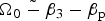
Equation (19) describes the coupling between the transverse current density and the transverse electric fields of the scattered wave. If the cyclotron frequency equals to the difference between the electron axial and phase velocity of the wave (i.e.,
 $\Omega _0 \;\tilde -\; {\rm \beta} _3 - {\rm \beta} _{\rm p} $
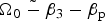
), then the denominator in the steady-state transverse velocity [Eqs. (8) and (9)] equals to zero and there will be a singularity at this point which is called the magnetoresonance point. This limits the group I and II trajectories to axial magnetic field below some critical values (given by the criterion Ω0 < 0.9 for group I and Ω0 > 0.95 for group II for the chosen parameter ωp = 2.24) and the trajectory curve breaks down in two distinct groups at this point. In the vicinity of the magnetic resonance at
 $\Omega _0 \;\tilde -\; {\rm \beta} _3 - {\rm \beta} _{\rm p} $
the resonant interaction between plasma electrons and laser pulse occurs which can cause an increase in the kinetic energy of the plasma electrons, so they can easily exchange energy with the propagating laser pulse. In addition, the energy contained in the plasma electrons could be effectively transferred to the scattered wave through the FEL coupling process. In order to illustrate the nature of the growth rate in the free-electron laser (FEL), the dispersion equation should be solved numerically and the range of axial magnetic field values should be picked corresponding to the region of group I and II orbits. Since these orbital trajectories are singular, it should be noted that the growth rate have a general increase in the resonance frequency. Therefore in a FEL, the gain, growth rate, and the efficiency are sensitively dependent on the axial velocity spread of the electrons. The peak of growth rate would increase to reach its maximum corresponding to the vicinity of magnetic resonance frequency and there would be an overall augmentation and decrement in the growth before and after the resonance frequency. It means that the transverse velocity of the electron increases as the cyclotron frequency approaches the resonance. It should be noted that such enhancement in the transverse velocity correspond to the decrease in the axial velocity of the electrons due to the presence of an axial magnetic field, and therefore correspond to the decrease in the resonant frequency of interaction.
4. NUMERICAL RESULTS AND DISCUSSION
A numerical analysis of the electron trajectories and the growth rate of a relativistic electron beam (REB) propagating parallel to a laser pulse in a plasma medium have been made in this section. The physical mechanism is as follows: the transverse electric field of the laser pulse induces a transverse motion on the beam electrons and also on the plasma background electrons leading to the formation of a ponderomotive force and the energy transition of the electrons into the EM energy of the scattered wave. In fact, the ponderomotive potential is based on the energy of the electron due to its transverse quiver motion in the laser field. Let us consider a test plasma electron initially at rest far from the peak of the pulse in the laboratory frame. As the electron goes up the ponderomotive potential barrier of the laser pulse, its kinetic energy, namely the part of energy due to its longitudinal motion, decreases and the potential energy increases until the electron reaches its maximum height on the potential barrier. In this case, the energy of the electron is transferred completely to the transverse direction. At this time the electron energy is purely potential. Since the peak amplitude of the ponderomotive potential or the peak intensity of the laser pulse is sufficiently large the electron can be trapped by the pulse. Since this laser pulse has a group velocity less than the speed of light in a plasma medium, it can act as a slow wave undulator, and therefore, the injected electron beam can be in synchronism the pulse. Besides, an axial guide magnetic field is employed to confine the transverse motion of the electron beam near the z-axis. The presence of the axial magnetic field can substantially modify many of the characteristics of the interaction. In the first place, the electron beam becomes more focused while traveling in the undulator section due to the axial guide magnetic field and the electrons execute cyclotron oscillations in the transverse plane. In the second place, the enhancements in the gain and growth rate when the Larmor period and undulator periods are comparable are present for the systems.
The graph of the normalized axial velocity of e-beam, β3 versus the normalized cyclotron frequency, is shown in Figure 2a–2c. The chosen parameters are γ = 40, Ωw = 0.05, ωb = 0.08, and ωp = 0.6, 2.24, 3.46. As seen in these figures, by increasing plasma frequency or plasma density, the maximum value of group I orbits decreases and the width of the curve increases to a higher value of normalized cyclotron frequencies. For group II orbits, by increasing plasma frequency, the curve shifts to left, that is, to lower values of normalized cyclotron frequencies. Finally, for group III orbits by increasing plasma density the curve shifts to higher values of normalized frequencies as it is evident in Figure 2c.
The graph of normalized growth rate,
 ${\rm Im} \,{\tilde {\rm \omega}}, $
as a function of normalized wave number,
 $\tilde k,$
has been depicted in Figures 3–11. To plot these figures, the coupled Eqs. of (11) and (12) have been solved simultaneously to obtain β3 and βp in terms of Ω0 and then we substitute them into Eq. (19). By passing a REB parallel to a laser pulse through background plasma, high-frequency radiation can be generated by coupling the EM wave (i.e., laser pulse) to the negative energy beam modes. The negative energy (or slow wave) electrostatic beam mode and the positive energy (or fast wave) EM laser pulse, in the presence of the plasma background, get strongly coupled together and therefore it leads to instability. The graph of the normalized growth rate for different values of plasma frequencies has been shown in Figures 3–5. As seen in these figures, by choosing higher magnitudes of plasma frequency for group I orbits, ωp, (ωp = 0.6, 2.24, and 3.46) the peak of the growth rate greatly decreases and also shifts to left (to lower magnitudes of
 $\tilde k$
). For group II orbits, by increasing the plasma frequency, the peak growth rate increases, as shown in Figure 4. Finally, for group III orbits (Fig. 5), increasing the plasma frequency causes an increase in the growth rate and the curves become smoother in higher plasma frequencies.
Graph of the normalized growth rate,
 ${\rm Im} \;{\tilde {\rm \omega}}, $
versus the normalized wave number
 $\tilde k,$
for group I orbits with parameters ωb = 0.08, γ = 40, Ωw = 0.05, Ω0 = 0.62,
 $\tilde v_{{\rm th}} = 0.6$
.

Graph of the normalized growth rate,
 ${\rm Im} \;{\tilde {\rm \omega}}, $
versus the normalized wave number
 $\tilde k,$
for group II orbits with parameters ωb = 0.08, γ = 40, Ωw = 0.05, Ω0 = 1.4,
 $\tilde v_{{\rm th}} = 0.6$
.

Graph of the normalized growth rate,
 ${\rm Im} \;{\tilde {\rm \omega}}, $
versus the normalized wave number
 $\tilde k,$
for group III orbits with parameters ωb = 0.08, γ = 40, Ωw = 0.05, Ω0 = 0.12,
 $\tilde v_{{\rm th}} = 0.6$
.

The graph of the normalized growth rate as a function of the normalized wave number, for different values of cyclotron frequencies Ω0, has been depicted in Figures 6–8. The peak growth rate for group I orbits by choosing higher values of cyclotron frequency, (Ω0 = 0.32, 0.62, and 0.88) increases to reach its maximum corresponding to the vicinity of magnetoresonance frequency (
 $\Omega _0 \tilde - 0.92$
). As we see in Figure 6 there is an increase in the peak of the growth rate for Ω0 = 0.88 (which is near to the resonance frequency for group I orbits). For group II orbits, an increase in the cyclotron frequency (Ω0 = 1.2, 1.4, and 1.6) causes a decrease in the peak of the growth rate. For values near to magnetoresonance frequency, the peak of the growth rate is much bigger compared to those far from the resonance value, in group II orbits. The general increase before and decrease after the resonance point in the growth rate is apparent in Figures 6 and 7, respectively. That means the transverse velocity of the electron beam increases as the cyclotron frequency moves toward the resonance due to the decrease in the axial velocity of the electrons in the presence of an axial guide magnetic field. When
 $\Omega _0 \tilde - {\rm \beta} _3 - {\rm \beta} _{\rm p} $
is approximately satisfied, the resonant interaction between plasma electrons and laser pulse occurs, which can cause an increase in the kinetic energy of the plasma electrons, so they can easily exchange energy with the propagating laser pulse. This is why the FEL instability presents a coupling process. As shown in Figure 9 by selecting higher values of cyclotron frequency (Ω0 = 0.08, 0.16, and 0.22) the growth rate increases and a smoother curve has been attained.
Graph of the normalized growth rate,
 ${\rm Im} \;{\tilde {\rm \omega}}, $
versus the normalized wave number
 $\tilde k,$
for group I orbits with parameters ωb = 0.08, γ = 40, Ωw = 0.05,
 $\mathop {\rm \omega} \nolimits_{\rm p} = 2.24,$
 $\tilde v_{{\rm th}} = 0.6$
.

Graph of the normalized growth rate,
 ${\rm Im} \;{\tilde {\rm \omega},} $
versus the normalized wave number
 $\tilde k,$
for group II orbits with parameters ωb = 0.08, γ = 40, Ωw = 0.05,
 $\mathop {\rm \omega} \nolimits_{\rm p} = 2.24,$
 $\tilde v_{{\rm th}} = 0.6$
.

Graph of the normalized growth rate,
 ${\rm Im} \;{\tilde {\rm \omega},} $
versus the normalized wave number
 $\tilde k,$
for group III orbits with parameters ωb = 0.08, γ = 40, Ωw = 0.05,
 $\mathop {\rm \omega} \nolimits_{\rm p} = 2.24,$
 $\tilde v_{{\rm th}} = 0.6$
.

Graph of the normalized growth rate,
 ${\rm Im} \;{\tilde {\rm \omega},} $
the versus normalized wave number
 $\tilde k,$
for group I orbits with parameters ωb = 0.08, γ = 40, Ωw = 0.05,
 $\mathop {\rm \omega} \nolimits_{\rm p} = 2.24,$
Ω0 = 0.62.

Figures 9–11 shows the graph of the normalized growth rate versus the normalized wave number for cold electron beam (i.e.,
 $\tilde v_{{\rm th}} = 0$
) and warm beams (i.e.,
 $\tilde v_{{\rm th}} = 0.3,$
0.6). As shown in Figures 9 and 10, by choosing more magnitudes of normalized thermal velocity, the growth rate for group I and III orbits trivially decreases because of the thermal motion of the electrons. In other words, for these groups of orbits the electrons in a warm beam run out of resonance with the radiation fields, due to their thermal motion. As can be seen in Figure 10, for group II orbits, by increasing the values of normalized thermal velocity, both the peak growth and band width of the curve increase, which means that the plasma oscillations are coupled to the EM waves through the transverse component of the magnetic field and perturbation resulting from the thermal motion are more significant. Therefore the instabilities, tend to be stronger compared with cold electron beams and consequently the growth rate for group II orbits becomes bigger.
Graph of the normalized growth rate,
 ${\rm Im} \;{\tilde {\rm \omega},} $
the versus normalized wave number
 $\tilde k,$
for group II orbits with parameters ωb = 0.08, γ = 40, Ωw = 0.05,
 $\mathop {\rm \omega} \nolimits_{\rm p} = 2.24,$
Ω0 = 1.4.

Graph of the normalized growth rate,
 ${\rm Im} \;{\tilde {\rm \omega},} $
versus normalized wave number
 $\tilde k,$
for group III orbits with parameters ωb = 0.08, γ = 40, Ωw = 0.05,
 $\mathop {\rm \omega} \nolimits_{\rm p} = 2.24,$
Ω0 = 0.12.

5. CONCLUSIONS
In this paper, we have presented a theory for FELs in which a linearly polarized laser pulse propagates parallel to a REB in the presence of a plasma background. It should be possible to reach the XUV and X-ray regimes using less expensive and more compact low γ by decreasing the undulator period λw. A suitable approach that has been suggested for decreasing λw is to replace the magnetostatic wiggler with a laser undulator. The undulator wavelength at the μm level allows one to reach the wavelength range from a few nm down to a few Å with moderately relativistic electrons of kinetic energies of tens of Mev. Several reasons exist for improvement the power of the FEL when a background of plasma present in the interaction region. Firstly, beam current enhances in the presence of the plasma in contrast with the vacuum-FEL. Secondly, the electron bunching process can be improved. Thirdly, the electron trajectory has a transverse drift in the plasma background while the conventional FELs did not have such drift, so radiation guiding would be enhanced. Taking the advantages of the plasma background for FELs, it may be an interesting way toward producing compact short wavelength FELs. By passing a relativistic e-beam through a laser undulator, high-frequency EM radiation is produced by coupling the EM wave to the negative energy electrostatic beam modes. This negative beam mode and the positive energy EM wave can strongly couple together and therefore leads to an instability, the amplitudes of beam modes increase and the waves begin to trap the electrons. Because of the relativistic effect on the mass of the electrons, the bounce period of the electrons trapped in the electrostatic potential well is long. During the bounce period, the unstable EM waves continue to grow to overshoot. This overshoot of the wave amplitudes results in further energy deposition into the EM radiation. By using the numerical solutions, the graph of electron beam axial velocity versus cyclotron frequency was obtained. As shown in Figure 2 the electron trajectories break down into three different groups of orbits, namely as G I, G II, and G III orbits, respectively. The group I orbits occur in Ω0 < 0.9, the group II orbits occur in Ω0 > 0.95 and the group III is broadened from about zero to near 2 (for ωp = 2.24). It can be seen that with changing in the plasma frequency (or plasma density), a considerable change was found in the maximum values of the group orbits of I, II, and III, respectively. Moreover, changing in the plasma frequency, results in an important shift in starting and resonance points of orbits of these three groups, which do not happen due to variation of other device parameters such as ωb, Ω0, Ωw, or γ. The dispersion relation was derived by solving the momentum transfer, continuity, and wave equations. Numerical studies have shown that the growth rate is sensitive to plasma density, e-beam temperature, and cyclotron frequency of the external magnetic field. By increasing the plasma frequency the growth rate for group I and II orbits decreased while for group III increased. It was found that by increasing the axial guide magnetic field strength, the growth rate for orbits of group I increased, while a decrement in growth rate was obtained for the orbits of groups II and III. Besides, by choosing more magnitudes of normalized thermal velocity, the peak growth rate for group I and III orbits trivially decreased, while for group II increased. Considering these fundamental parameters will lead higher tunability in FELs relative to conventional ones.
APPENDIX A
A1. DISPERSION RELATION DERIVATION
The Floquet theorem can be used to derive the dispersion equation; by using the axial and time dependence of all perturbed parameters take the general form,
 $$X = \sum\limits_{n = - \infty} ^{n = + \infty} {x_n \exp [i(k_n z - {\rm \omega} t)]},$$
with k n = k + nk L, (n = 0, ± 1, ± 2, …), ω and k n denote the frequency and wave number of mixed, radiation, and space charge waves, respectively. Substituting Eqs. (8)–(10) and (14)–(16) into Eqs. (4) and (13), assuming small transverse oscillations (i.e., ∂/∂x and ∂/∂y are ≪ ∂/∂z), and using orthogonality relation,
 $$\int_0^l {\exp [i(k_n} - k_m )z]dz = l{\rm \delta} _{mn} $$
and
 $$\int_0^T {\exp [i({\rm \omega}} - {\rm \omega} ^{\prime})t]dt = T{\rm \delta} _{{\rm \omega} {\rm \omega} ^{\prime}}, $$
we obtain the normalized perturbed velocity components as follows:
 $$\eqalign{{\rm \beta} _{xn} = & \displaystyle{{ - ie} \over {{\rm \gamma} _0 mc^2 k_{\rm L}}} \left[ {\displaystyle{{(1 - {\rm \beta} _3 (\tilde k_n /{\tilde {\rm \omega}} ))E_{xn} + B_0 {\rm \beta} _{yn}} \over {\Omega _n ({\tilde {\rm \omega}} )}}} \right. \cr & \left. { + \displaystyle{{i{\rm \beta} _3 \Omega _{\rm L} ({\rm \beta} _3 - {\rm \beta} _{\rm p} )^2} \over {2[({\rm \beta} _3 - {\rm \beta} _{\rm p} )^2 - \Omega _0^2 ]}}\left( {\displaystyle{{E_{\ln - 1}} \over {\Omega _n ({\tilde {\rm \omega}} - {\rm \beta} _{\rm p} )}} - \displaystyle{{E_{\ln + 1}} \over {\Omega _n ({\tilde {\rm \omega}} + {\rm \beta} _{\rm p} )}}} \right)} \right] \cr & - \displaystyle{{ie} \over {2{\rm \gamma} _0 mc^2 k_{\rm L}}} \left[ {{\rm \beta} _3 \left( {B_{\rm L} ({\rm \beta} _3 - {\rm \beta} _{\rm p} ) + \displaystyle{{\Omega _{\rm w} \Omega _0 ({\rm \beta} _3 - {\rm \beta} _{\rm p} )} \over {[({\rm \beta} _3 - {\rm \beta} _{\rm p} )^2 - \Omega _0^2 ]}}} \right) - \displaystyle{{B_{\rm L}} \over {{\rm \gamma} _0^2}}} \right] \cr & \quad \left( {\displaystyle{{{\rm \beta} _{zn - 1}} \over {\Omega _n ({\tilde {\rm \omega}} - {\rm \beta} _{\rm p} )}} + \displaystyle{{{\rm \beta} _{zn + 1}} \over {\Omega _n ({\tilde {\rm \omega}} + {\rm \beta} _{\rm p} )}}} \right),}$$
 $$\eqalign{{\rm \beta} _{yn} = & \displaystyle{{ - ie} \over {{\rm \gamma} _0 mc^2 k_{\rm L}}} \left[ {\displaystyle{{(1 - {\rm \beta} _3 (\tilde k_n /{\tilde {\rm \omega}} ))E_{yn} - B_0 {\rm \beta} _{xn}} \over {\Omega _n ({\tilde {\rm \omega}} )}} +} \right. \cr & \left. {\displaystyle{{\Omega _0 \Omega _{\rm L} ({\rm \beta} _3 - {\rm \beta} _{\rm p} )} \over {2[({\rm \beta} _3 - {\rm \beta} _{\rm p} )^2 - \Omega _0^2 ]}}\left( {\displaystyle{{E_{\ln - 1}} \over {\Omega _n ({\tilde {\rm \omega}} - {\rm \beta} _{\rm p} )}} + \displaystyle{{E_{\ln + 1}} \over {\Omega _n ({\tilde {\rm \omega}} + {\rm \beta} _{\rm p} )}}} \right)} \right] \cr & + \displaystyle{{{\rm \beta} _3 {\rm \gamma} _0^2 \Omega _{\rm L} \Omega _0 ({\rm \beta} _3 - {\rm \beta} _{\rm p} )^2} \over {2[({\rm \beta} _3 - {\rm \beta} _{\rm p} )^2 - \Omega _0^2 ]}}\left( {\displaystyle{{{\rm \beta} _{zn - 1}} \over {\Omega _n ({\tilde {\rm \omega}} - {\rm \beta} _{\rm p} )}} - \displaystyle{{{\rm \beta} _{zn + 1}} \over {\Omega _n ({\tilde {\rm \omega}} + {\rm \beta} _{\rm p} )}}} \right),} $$
 $$\eqalign{{\rm \beta} _{zn} = & \displaystyle{{ - ie\Omega _n^2 ({\tilde {\rm \omega}} )} \over {{\rm \gamma} _0 mc^2 k_{\rm L} \left(\Omega _n^2 ({\tilde {\rm \omega}} ) - (3{\tilde k}_n^2 v_{{\rm th}}^{\rm 2} /{\rm \gamma}_0 ) \right)}}\cr & \quad \left[ \displaystyle{{E_{\ln}} \over {{\rm \gamma} _3^2 \Omega _n ({\tilde {\rm \omega}})}} - \displaystyle{{i \Omega _{\rm L} ({\rm \beta} _3 - {\rm \beta} _{\rm p} )^2} \over {2{\tilde {\rm \omega}} [({\rm \beta} _3 - {\rm \beta} _{\rm p} )^2 - \Omega _0^2 ]}} \right. \cr & \quad \left( \displaystyle{{\tilde k_{n - 1} E_{xn - 1}} \over {\Omega _n ({\tilde {\rm \omega}} - {\rm \beta} _{\rm p} )}} - \displaystyle{{\tilde k_{n + 1} E_{xn + 1}} \over {\Omega _n ({\tilde {\rm \omega}} + {\rm \beta} _{\rm p} )}} \right) \cr & - \displaystyle{{\Omega _0 \Omega _{\rm L} ({\rm \beta} _3 - {\rm \beta} _{\rm p} )} \over {2{\tilde {\rm \omega}} [({\rm \beta} _3 - {\rm \beta} _{\rm p} )^2 - \Omega _0^2 ]}} \left(\displaystyle{{{\tilde k}_{n - 1} E_{yn - 1}} \over {\Omega _n ({\tilde {\rm \omega}} - {\rm \beta} _{\rm p} )}} + \displaystyle{{{\tilde k}_{n + 1} E_{yn + 1}} \over {\Omega _n ({\tilde {\rm \omega}} + {\rm \beta} _{\rm p} )}} \right) \cr & \quad + \displaystyle{{i{\rm \beta} _3 \Omega _{\rm L} ({\rm \beta} _3 - {\rm \beta} _{\rm p} )^2} \over {2[({\rm \beta} _3 - {\rm \beta} _{\rm p} )^2 - \Omega _0^2 ]}} \left(\displaystyle{{E_{xn - 1}} \over {\Omega _n ({\tilde {\rm \omega}} - {\rm \beta} _{\rm p} )}} - \displaystyle{{E_{xn + 1}} \over {\Omega _n ({\tilde {\rm \omega}} + {\rm \beta} _{\rm p} )}} \right) \cr & \left. {+ \displaystyle{{B_{\rm L}} \over 2}\left( \displaystyle{{{\rm \beta} _{zn - 1}} \over {\Omega _n ({\tilde {\rm \omega}} - {\rm \beta} _{\rm p} )}} - \displaystyle{{{\rm \beta} _{zn + 1}} \over {\Omega _n ({\tilde {\rm \omega}} + {\rm \beta} _{\rm p} )}} \right)} \right],} $$
in which we use Faraday's law (to eliminate the perturbed magnetic field) and
 $\Omega _n ({\tilde {\rm \omega}} ) = {\tilde {\rm \omega}} - {\rm \beta} _3 \tilde k_n, $
 $\tilde k_n = k_n /k_{\rm w}, $
 ${\tilde {\rm \omega}} = {\rm \omega} /ck_{\rm w}, $
 $\Omega _n ({\tilde {\rm \omega}} \pm {\rm \beta} _{\rm p} ) = {\tilde {\rm \omega}} \pm {\rm \beta} _{\rm p} - {\rm \beta} _3 \tilde k_n, $
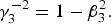 ${\rm \gamma} _3^{ - 2} = 1 - {\rm \beta} _{\rm 3}^{\rm 2}. $
Here v
th = (K
B
T/m)1/2 is the thermal velocity of the electron beam (where K
B is the Boltzmann's constant and T is the temperature of the electron beam).
Using continuity equation and linearizing it yields,
 $$\displaystyle{{\partial n} \over {\partial t}} + \nabla \cdot (n{\bf V}) = 0,$$
 $$n_n = \displaystyle{{\tilde k_n n_0 {\rm \beta} _3} \over {\Omega _n ({\tilde {\rm \omega}} )}.} $$
The current density has the form
 ${\bf J} = J_x {\bf x} + J_y {\bf y} + J_z {\bf z},$
where
 $$\left( {\matrix{ {J_x} \cr {J_y} \cr {J_z} \cr}} \right) = \sum\limits_{n = - \infty} ^\infty {\left( {\matrix{ {J_{xn}} \cr {J_{yn}} \cr {J_{zn}} \cr}} \right)} \exp [i(k_n z - {\rm \omega} t)].$$
Using Eq. (A6), the current density component amplitudes can be expressed as
 $$\eqalign{J_{xn} & = - en_0 c{\rm \beta} _{xn} - en_0 c\displaystyle{{\Omega _{\rm L} ({\rm \beta} _3 - {\rm \beta} _{\rm p} )^2} \over {2i[({\rm \beta} _3 - {\rm \beta} _{\rm p} )^2 - \Omega _0^2 ]}} \cr & \quad \left( {\displaystyle{{\tilde k_{n - 1}} \over {\Omega _{n - 1} ({\tilde {\rm \omega}} - {\rm \beta} _{\rm p} )}}{\rm \beta} _{zn - 1} - \displaystyle{{\tilde k_{n + 1}} \over {\Omega _{n + 1} ({\tilde {\rm \omega}} - {\rm \beta} _{\rm p} )}}{\rm \beta} _{zn + 1}} \right),} $$
 $$\eqalign{J_{yn} & = - en_0 c{\rm \beta} _{yn} + en_0 c\displaystyle{{\Omega _0 \Omega _{\rm L} ({\rm \beta} _3 - {\rm \beta} _{\rm p} )} \over {2[({\rm \beta} _3 - {\rm \beta} _{\rm p} )^2 - \Omega _0^2 ]}} \cr & \quad \left( {\displaystyle{{\tilde k_{n - 1}} \over {\Omega _{n - 1} ({\tilde {\rm \omega}} - {\rm \beta} _{\rm p} )}}{\rm \beta} _{zn - 1} + \displaystyle{{\tilde k_{n + 1}} \over {\Omega _{n + 1} ({\tilde {\rm \omega}} - {\rm \beta} _{\rm p} )}}{\rm \beta} _{zn + 1}} \right),} $$
 $$J_{zn} = \displaystyle{{ - en_0 {\tilde {\rm \omega}}} \over {\Omega _n ({\tilde {\rm \omega}} )}}c{\rm \beta} _{zn}.$$
With the restrictions ∂/∂x, ∂/∂y ≪ ∂/∂z, and assuming the z and T dependence of Eq. (A1) for E x,y,z and J x,y,z this equation leads to
 $$\left( {k_n - \displaystyle{{{\rm \omega} ^2} \over {c^2}}} \right)\left( {\matrix{ {E_{xn}} \cr {E_{yn}} \cr}} \right) - \displaystyle{{4{\rm \pi} i{\rm \omega}} \over {c^2}} \left( {\matrix{ {J_{xn}} \cr {J_{yn}} \cr}} \right) = 0,$$
 $$- \displaystyle{{{\rm \omega} ^2} \over {c^2}} - \displaystyle{{4{\rm \pi} i{\rm \omega}} \over {c^2}} J_{zn} = 0.$$
The normalized dispersion relation is obtained by substituting the source currents, Eqs. (A8)–(A10), and the perturbed velocities (A2)–(A4), into the scalar wave equations; the result is
 $$\eqalign{& \left\{ {{\tilde {\rm \omega}} ^2 - \tilde k_n ^2 - {\tilde {\rm \omega}} _{\rm b}^{\rm 2} + \displaystyle{{{\tilde {\rm \omega}} _{\rm b}^{\rm 2} \Omega _{\rm L}^{\rm 2} ({\rm \beta} _3 - {\rm \beta} _{\rm p} )^4} \over {4\Gamma _{n, +} [({\rm \beta} _3 - {\rm \beta} _{\rm p} )^2 - \Omega _{\rm 0}^{\rm 2} ]^2}}} \right. \cr & \quad \left( {\displaystyle{1 \over {\Omega _n ({\tilde {\rm \omega}} - {\rm \beta} _{\rm p} )}} + \displaystyle{1 \over {\Omega _n ({\tilde {\rm \omega}} + {\rm \beta} _{\rm p} )}}} \right) + \displaystyle{{{\tilde {\rm \omega}} _{\rm b}^{\rm 2} \Omega _{\rm L}^{\rm 2} ({\rm \beta} _{\rm 3} - {\rm \beta} _{\rm p} {\rm )}^2} \over {4\Gamma _{n, +} [({\rm \beta} _{\rm 3} - {\rm \beta} _{\rm p} {\rm )}^2 - \Omega _{\rm 0}^{\rm 2} ]}} \cr & \quad \left( {\displaystyle{1 \over {\Omega _n ({\tilde {\rm \omega}} - {\rm \beta} _{\rm p} {\rm )}}} - \displaystyle{1 \over {\Omega _n ({\tilde {\rm \omega}} + {\rm \beta} _{\rm p} {\rm )}}}} \right)\Bigg\} \cr & \quad \times \left\{ {{\tilde {\rm \omega}} ^2 - \tilde k_n ^2 - {\tilde {\rm \omega}} _{\rm b}^{\rm 2} + \displaystyle{{i{\tilde {\rm \omega}} _{\rm b}^{\rm 2} \Omega _{\rm L}^{\rm 2} \Omega _{\rm 0}^{\rm 2} ({\rm \beta} _3 - {\rm \beta} _{\rm p} )^2} \over {4\Gamma _{n, +} [({\rm \beta} _3 - {\rm \beta} _{\rm p} {\rm )}^2 - \Omega _{\rm 0}^{\rm 2} ]^2}}} \right. \cr & \qquad \left( {\displaystyle{1 \over {\Omega _n ({\tilde {\rm \omega}} - {\rm \beta} _{\rm p} )}} + \displaystyle{1 \over {\Omega _n ({\tilde {\rm \omega}} + {\rm \beta} _{\rm p} )}}} \right)\Bigg\} \cr & \quad = \displaystyle{{{\tilde {\rm \omega}} _{\rm b}^{\rm 4} \Omega _{\rm L}^{\rm 2} \Omega _{\rm 0}^{\rm 2} ({\rm \beta} _3 - {\rm \beta} _{\rm p} )^6} \over {16\Gamma _{n, -} ^2 [({\rm \beta} _{\rm 3} - {\rm \beta} _{\rm p} {\rm )}^2 - \Omega _{\rm 0}^{\rm 2} ]^4}} \cr & \qquad \left( {\displaystyle{1 \over {\Omega _n ({\tilde {\rm \omega}} - {\rm \beta} _{\rm p} )}} - \displaystyle{1 \over {\Omega _n ({\tilde {\rm \omega}} + {\rm \beta} _{\rm p} {\rm )}}}} \right)^2 \cr &\quad + \displaystyle{{{\tilde {\rm \omega}} _{\rm b}^{\rm 4} \Omega _{\rm L}^{\rm 4} \Omega _0^2 ({\rm \beta} _3 - {\rm \beta} _{\rm p} )^4} \over {4\Gamma _{n, +} \Gamma _{n, -} [({\rm \beta} _3 - {\rm \beta} _{\rm p} )^2 - \Omega _{\rm 0}^{\rm 2} ]}}\left( {\displaystyle{1 \over {\Omega _n^2 ({\tilde {\rm \omega}} - {\rm \beta} _{\rm p} )}} - \displaystyle{1 \over {\Omega _n^2 ({\tilde {\rm \omega}} + {\rm \beta} _{\rm p} )}}} \right),} $$
where
 $$\eqalign{\displaystyle{1 \over {\Gamma _{n, \pm}}} & = \displaystyle{{\tilde k_{n + 1}} \over {\Omega _{n + 1} ({\tilde {\rm \omega}} - {\rm \beta} _{\rm p} ) - (3\tilde k_{n + 1}^2 \tilde v_{{\rm th}}^{\rm 2} /{\rm \gamma} _0 )}} \cr & \quad \pm \displaystyle{{\tilde k_{n - 1}} \over {\Omega _{n - 1} ({\tilde {\rm \omega}} + {\rm \beta} _{\rm p} ) - (3\tilde k_{n - 1}^2 \tilde v_{{\rm th}}^{\rm 2} /{\rm \gamma} _0 )}}.} $$



