I. INTRODUCTION
Radiofrequency identification (RFID) technology working in UHF represents one of the most important and consolidated examples of a wireless power transfer (WPT) system where the electromagnetic energy is wirelessly exchanged between two devices: the reader and the tag. More specifically, the tag is a fully passive device equipped with an antenna and a chip embedding an energy harvesting circuit, which converts the radiofrequency signal (RF) provided by the reader antennas into DC voltage useful to power-up its internal circuitry [Reference Roselli1–Reference Fantuzzi, Masotti and Costanzo6]. For such a reason, the effectiveness of the whole RFID system relies most of all on the performance of the tag itself, which ultimately depends on both the chip sensitivity (i.e. the minimum power to turn-on the internal energy harvester) and the goodness of the conjugate matching between chip and tag antenna [Reference Nikitin, Rao and Lam7]. Factors like the need of compactness and low-cost, the use of flexible paper-based substrates and conductive inks [Reference Tentzeris8], or more simply the composition of the material on which the tag is attached to could strongly affect the WPT link and then the tag performance. In order to take into account all these factors and then to implement appropriate tag design strategies aiming at preserving performance, reliability, robustness, and working distance, the development of novel kinds of test environments, tools, and methods suitable for UHF RFID tag characterization is becoming a topic of interest for both Industrial and Scientific Communities.
At the state of the art, commercially available measurement systems are essentially used to characterize RFID tags. Among all the possible solutions [Reference Tentzeris8], the LabVIEW-controlled PXI RF platform by National Instruments [9] and the Voyantic Tagformance Lite tool [10] are frequently used thanks to their requirements of reliability and controllability. These systems are extremely accurate but cost several tens of thousands of dollars.
From the scientific literature point of view, different kinds of methods have been proposed. Some of them are based on direct measurements of some important RFID tag parameters, such as chip or tag antenna impedance. Some others characterize the assembled tags through over-the-air methods by analyzing the backscattered signal. In [Reference Chen and Lin11], for instance, the accurate RFID chip impedance measurement is performed by means of a single-ended probe and a vector network analyzer (VNA). Also in [Reference Nikitin, Rao, Martinez and Lam12] a method for the chip impedance measurement based on the use of the National Instrument PXI RF platform [9] is validated. In [Reference Palmer and Rooyen13–Reference Zhu, Ko and Ye15], specific text fixtures suitable for the impedance measurement of balanced RFID tag antennas are proposed.
Differently from such methods, over-the-air techniques allow for a characterization of the assembled tag. In [Reference Nikitin, Rao and Martinez16], the NI instrument platform is used to interrogate an RFID tag and derive its differential radar cross section (ΔRCS). Based on the use of the Voyantic TagFormance platform, some different RFID tag characterization methods are proposed. In particular, in [Reference Sydanheimol, Nummela, Ukkonen, McVay, Hoorfar and Kivikoski17] the tag ΔRCS as well as and the tag threshold power level, i.e. the minimum RFID reader emitted power turning on a tag at a certain distance, are computed. Instead, in [Reference Adel, Bauer and Grabowski18] the tridimensional radiation pattern (RP) of a tag is measured through the same Voyantic TagFormance.
Another approach, not making use of any commercial RFID tester was proposed by our research group [Reference Catarinucci, De Donno, Colella, Ricciato and Tarricone19, Reference De Donno, Catarinucci, Colella, Ricciato and Tarricone20] in 2012. It is based on an open-source SDR (Software-Defined Radio) [21, Reference Buettner and Wetherall22] implementation of a RFID reader, thus combining flexibility, accuracy, and cost-effectiveness. Nevertheless, restrictions on the maximum emitted power (250 mW only) and the need of two separate antennas for transmitting and receiving functions make difficult the setting up of a system suitable, for instance, for angular-dependent measurement. Indeed, angular tag sensitivity evaluation requires a power excursion as large as possible so to energize the tag when varying the angular position and, hence, the tag antenna gain.
Lying on a specific theoretical formulation of the EM problem, in this work a novel cost-effective system which allows for the fast calculation of a set of metrics characterizing an RFID tag as a function of the tag activation power threshold when varying both tag orientation and interrogation frequency in the 865–928 MHz band is proposed. The system is optimized to estimate RP, sensitivity, and reading distance of RFID tags through an over-the-air analysis when chip and antenna are assembled together. Hence, antenna gain, quality of antenna–chip conjugate matching, and substrate are contemporarily taken into account.
Even if the system is much less expensive than commercial solutions on the market [9, 10] (below 2000€ for the hardware), it is still accurate enough, very user-friendly, and easy to replicate. Moreover, compared with our previous solutions [Reference Catarinucci, De Donno, Colella, Ricciato and Tarricone19], it is more flexible, supports the evaluation of the interested metrics even when varying the interrogation angle, and guarantees a larger power excursion and, consequently, a finer detection of the tag activation power threshold.
More in detail, the RFID tag characterization system is composed of a hardware and a software subsystem. The former lies on a multi-programmable, multi-standard, GPIO-provided UHF RFID reader connected to a circularly polarized antenna and driving a stepper motor. The latter controls the hardware subsystem and processes the measured raw data. The whole system is able to evaluate all the relevant metrics characterizing an RFID tag also when varying the orientation between tag and reader antenna in steps as small as 1.8°.
Once implemented the novel characterization platform has been validated through a comparison with the Voyantic TagFormance Lite tool [10], and through a measurement campaign on three different commercial tags applied on different materials. Moreover, an experimental test has been carried out aimed at assessing the performance of flexible label-type RFID tags when applied on, or embedded into, electromagnetic hostile materials like the concrete.
II. THEORETICAL FORMULATION OF THE ELECTROMAGNETIC PROBLEM
In this section a theoretical definition of some metrics useful to evaluate the electromagnetic performance of a UHF RFID tag along with its radiation properties is presented.
As demonstrated in literature, in realistic environments the link between a UHF RFID reader and a tag is affected by multipath phenomena, so that the two-ray model or other more complex models should be adopted to study the communication channel. Nevertheless, since the proposed measurement system is thought to be used in an anechoic environment, the Friis's radiopropagation model becomes the most suitable one.
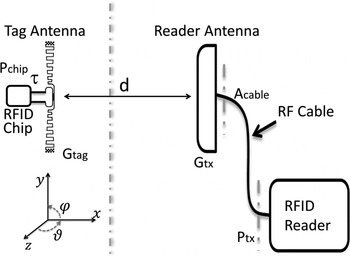
More in detail, let us consider the RFID communication system shown in Fig. 1 where both tag and reader antennas are placed along a straight horizontal line at a distance d large enough to guarantee the far-field condition. It is assumed that the reader antenna is kept fixed, while only the tag antenna can be rotated around its axes according to the reference system reported in the figure.
Friis's radiopropagation model for a passive UHF RFID system where the reader antenna is fixed and the tag can be rotated around its axes.

Under such assumptions, by using the Friis's formula the power reaching the RFID chip is given by:
 $$P_{chip,friis}(\theta, \varphi ) = P_{tx} \cdot G_{tx} \cdot G_{tag}(\theta, \varphi ) \cdot \tau \left( {\displaystyle{\lambda \over {4\pi d}}} \right)^2 \cdot \eta _{plf} \cdot A_{cable},$$
where in order to better describe only the possibility of the tag antenna to be arbitrarily oriented in the space, the gain of the reader antenna is assumed to be fixed and the gain of the tag antenna is assumed to be a function of (θ, ϕ). Moreover, P tx is the power transmitted from the reader, G tx is the maximum gain of the reader antenna, G tag (θ, ϕ) is the tag antenna gain, λ is the wavelength, d is the distance between RFID tag and reader (large enough to satisfy the far field condition), η plf is the polarization loss factor depending on the tag antenna structure, A cable is the attenuation due to the cable connecting reader and antenna and, finally, τis the power transmission coefficient between tag antenna and RFID chip.
Starting from (1), important metrics useful to quantify the performance of any RFID tag can be derived. In particular, let's consider to gradually increase, from zero to the maximum allowed value, the reader emitted power P tx and to contextually verify whether or not the tag is energized and answers to the reader. In this way, is it possible to experimentally determine the so-called tag activation power threshold, representing the minimum power emitted by the reader at which the tag starts working. When a power as large as the tag activation power threshold is emitted, the power at the chip terminal becomes the chip sensitivity S chip , that is constant and intrinsic characteristic of the RFID chip, usually reported in the chip datasheet. Consequently, (1) can be rewritten as:
 $$S_{chip} = P_{tx,ON}(\theta, \varphi ) \cdot G_{tx} \cdot G_{tag}(\theta, \varphi ) \cdot \tau \left( {\displaystyle{\lambda \over {4\pi d}}} \right)^2 \cdot \eta _{plf} \cdot A_{cable},$$
where it should be noted that the tag activation power threshold, denoted as P tx, ON (θ, φ), is an angle-dependent parameter, because if the interrogation angle changes, the minimum reader emitted power switching the tag on does change as well. Despite it is useful to characterize the chip quality, S chip is inadequate to quantify the goodness of the assembled tag, which definitely depends also on the quality of the tag antenna and on the quality of the conjugate matching between antenna and chip.
Instead, a significant metric is the sensitivity of the whole tag, S tag , which, as desired, depends on chip, antenna gain, and conjugate matching. Note that the lower is the tag sensitivity, the better is the tag.
Starting from (2), the tag sensitivity can be derived as a function of the tag activation power threshold P tx, ON (θ, φ):
 $$\eqalign{S_{tag}(\theta, \varphi ) & = \displaystyle{{S_{chip}} \over {\tau \cdot G_{tag}(\theta, \varphi )}} \cr & = P_{tx,ON}(\theta, \varphi ) \cdot G_{tx} \cdot \left( {\displaystyle{\lambda \over {4\pi d}}} \right)^2\eta _{plf} \cdot A_{cable}}$$
It is worth highlighting that the tag sensitivity evaluated in (3) is an angle-dependent parameter. Nevertheless, it could be also useful a performance evaluation when varying the frequency, so to verify the capability of a tag of working properly worldwide. By keeping constant the angles, the frequency-dependent tag sensitivity, once again as a function of the tag activation power threshold, can be written as:
 $$\eqalign{S_{tag}(f) & = \displaystyle{{S_{chip}} \over {\tau (f) \cdot G_{tag}\left( f \right)}} \cr & = P_{tx,ON}(f) \cdot G_{tx} \cdot \left( {\displaystyle{{c_{}} \over {4\pi df}}} \right)^2\eta _{plf} \cdot A_{cable}.}$$
Again, the tag sensitivity formulas (3) and (4) can be inverted in order to derive a parameter suitable also for non-technicians, such as the estimated maximum working distance by varying the angle:
 $$d_{\max} (\theta, \varphi ) = \displaystyle{\lambda \over {4\pi}} \sqrt {\displaystyle{{P_{tx,max} \cdot G_{tx} \cdot \eta _{plf} \cdot A_{cable}} \over {S_{tag}(\theta, \varphi )}}} $$
and by varying the frequency:
 $$d_{\max }(f) = \displaystyle{c \over {4\pi f}}\sqrt {\displaystyle{{P_{tx,max} \cdot G_{tx} \cdot \eta _{plf} \cdot A_{cable}} \over {S_{tag}(f)}}} . $$
Finally, another important tag characterization can be done in terms of RP of the tag antenna. Starting from (2) and after some simple steps, the tag antenna RP can be obtained as
 $$\eqalign{\displaystyle{{G_{tag}(\theta, \varphi )} \over {G{}_{tag,\max}}} & = \displaystyle{{S_{tag,\min}} \over {S_{tag}(\theta, \varphi )}} \cr & = \displaystyle{{P_{tx,ON,\min} \cdot G_{tx} \cdot {(\lambda /4\pi d)}^2 \cdot \eta _{plf}} \over {P_{tx,ON}(\theta, \varphi ) \cdot G_{tx} \cdot {(\lambda /4\pi d)}^2 \cdot \eta _{plf}}} \cr & = \displaystyle{{P_{tx,ON,\min}} \over {P_{tx,ON}(\theta, \varphi )}}.}$$
The five metrics (3)–(7), which would allow a complete characterization of a UHF RFID tag both by varying angle and frequency, directly or indirectly depends on the tag activation power threshold P tx, ON , once all the other static parameters of Fig. 1 (G tx , d, η plf , A cable ) are known. As already stated, P tx, ON could be evaluated for each angular- or frequency-step by gradually increasing the reader emitted power until the tag is energized. Consequently, as explained in the next section, the enabling element of the proposed system is a fully controllable RFID reader both in term of power and frequency, which allows the iterative evaluation of P tx, ON and the consequent evaluation, via software, of the desired metrics.
III. CHARACTERIZATION SYSTEM DESIGN AND IMPLEMENTATION
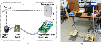
The architectural model of the proposed platform for UHF RFID Tag characterization and performance evaluation is illustrated in Fig. 2(a) and the system setup is shown in Fig. 2(b). As can be observed, the proposed measurement system is mainly composed of a fully-controllable UHF RFID reader board having its RF interface connected to a patch antenna with known electromagnetic characteristics and its digital interface connected to an automated rotating system. The selected reader board is the ThingMagic Mercury 6e (M6e) [23], which is equipped with four general purpose input output (GPIO) ports and which allows one to modify both the emitted power (in the range 5–31.5 dBm in steps of 0.5 dB) and the working frequency in the whole RFID bandwidth. It is worth highlighting that the wide power excursion along with the good power resolution of this reader allow for the implementation of a measurement procedure based on the iterative research of the tag activation power threshold P tx, ON . Besides the M6e, in order to implement the tag rotation with respect to the reader antenna, an unipolar stepper motor (Brother KE58KM2-032 with minimum angular step of 1.8°) has been selected. The stepper motor is controlled by the M6e GPIO ports through a properly designed driver board based on power transistors (see Fig. 2).
(a) Architecture of the proposed RFID tag characterization system. (b) Measurement setup: 1. Reader antenna, 2. Reader board 3. Driver Board, 4. Stepper Motor, 5. Coax Cable.

In order to carry out the performance evaluation of a tag, the main task to be performed by the proposed measurement platform is the individuation of the tag activation power threshold, as theorized in Section II. To perform this task a software subsystem implementing a specific measurement algorithm which iteratively detects the tag activation power threshold, has been designed so to drive the hardware subsystem in terms of emitted power, frequency, and stepper motor angular position. Definitely, the simplest algorithmic approach to individuate the activation threshold of an RFID tag consists of linearly scanning all the power values of the reader (starting from 5 dBm up to 31.5 dBm) in incremental steps of 0.5 dB until the minimum activation threshold is reached and the tag starts working. Despite the simplicity, this approach is both computationally onerous and time consuming due to the considerable number of iterations that might occur. In fact, in order to obtain a full tag characterization, the algorithm must be re-iterated for each angular step (corresponding to the minimum rotation of the stepper-motor of 1.8°) and for each frequency step (corresponding to minimum frequency variation of the reader of 1 MHz).
On the contrary, the proposed algorithm is based on a probabilistic consideration on the expected power value that minimizes the iteration number required to detect the tag activation threshold. Indeed, since angular steps are spatially very close to each other and, similarly, frequency steps are also small enough, it is reasonable to assume that tag activation power values for neighboring angular or frequency steps are correlated between them. According to this consideration, the idea of the proposed algorithm is to keep memory of the tag activation power detected at a certain measurement step (either angular step or frequency step) and then to use this last value as starting value in the next step. Then a generally very fast exploration performed around the starting power value allows the detection of the tag activation power threshold for each measurement step. In this way the scanning of the whole reader power range is no longer required.
After assembling the whole system, specific preliminary measurements have been carried out to take into account the effect of the cable connecting the antenna to the programmable reader as well as to calibrate the power actually emitted by the reader itself. In particular, as for the calibration of the programmable reader, the degree of coherence between nominal and actually emitted power in the whole power (5–31.5 dBm) and frequency (865–928 MHz) spans has been verified and a calibration pattern obtained. At each frequency step, the reader emitted power has been evaluated through a Spectrum Analyzer “Rohde&Schwarz” FSW and compared with the nominal one. For instance, an almost constant difference between nominal and actual power of about 1.1 dB on average has been observed and has been taken into account by means of an appropriate power calibration factor evaluated for each frequency step. Moreover, the evaluation of the attenuation A cable of the used CNT-195-FR coaxial cable, crucial for the evaluation of the metrics of Section II, has been performed with the VNA “Rohde&Schwarz” ZVL through a two-port S-parameter measurement. The obtained result is A cable = −0.53 dB.
IV. VALIDATION AND RESULTS
A) System validation and preliminary test
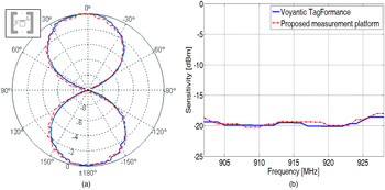
In this section, some validation tests are proposed in order to verify the capability of the proposed system of performing the electromagnetic characterization of any RFID tag also when varying the mutual orientation between reader antenna and tag. For this purpose, the comparison in terms of RFID tag RP with data obtained through the commercial Voyantic TagFormance has been firstly addressed. More specifically, the sensitivity of the broadband UHF RFID tag ALR-9634 (see inset of Fig. 3(a)) from Alien Technology has been measured in an anechoic environment at 866 MHz with an angular step of 3.6°, and the vertical RP has been consequently calculated through equation (7). The total time required for the whole measurement has been lower than 300 s. The measured RP has been then compared with the one reported in [Reference Ukkonen and Sydänheimo24] and obtained through the Voyantic TagFormance platform. The results, reported in Fig. 3(a), are in optimal agreement, thus demonstrating the ability of the proposed system to correctly estimate the RP of RFID tags. Figure 3(b), instead, is referred to the same kind of comparison performed in terms of tag sensitivity when varying the frequency in the whole RFID range. The perfect accordance among obtained results confirms once again the appropriateness of the proposed characterization platform also in case of sensitivity evaluation.
(a) Measured vertical RP s and (b) tag sensitivity of Alien ALR-9634 tag: comparison between the proposed system and Voyantic TagFormance.

Once experimentally validated, an example of application of the proposed system for easily and effortless create a taxonomy for RFID tags is proposed, in order to support, for instance, the selection of the most adequate tag for a specific use case. In particular, different RFID tags have been characterized when applied on different materials. Without loss of generality, in this case the USA RFID bandwidth instead of the European one has been analyzed. Each tag under test has been placed 1 m away from the interrogating antenna, a frequency step of 1 MHz has been considered, and a comparison in terms of tag sensitivity and maximum reading distance by varying the frequency has been performed. In particular, among the others, the SD UPM tag [25], a generic label-type tag, and the Xerafy Metal-Skin tag [26], specifically thought for on-metal applications, have been considered in this paper (see Table 1).
RFID tag selection.

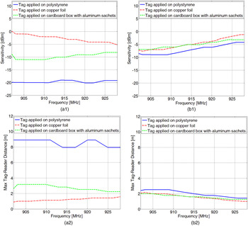
The two selected tags have been tested when applied on three different background materials: a polystyrene slab, as an example of low-permittivity and low-conductivity dielectric; a cardboard box containing aluminum sachets filled with liquids as an example of complex and heterogeneous material; a copper foil, as an example of good conductor. Before starting the measurement campaign, preliminary tests have been conducted, confirming the expected unsuitability of the label-type tag for direct on-metal applications. Consequently, only in the configuration UPM-SD on copper foil, a 7-mm-thick cardboard layer has been placed between metal and tag under test. Figure 4 shows the tag sensitivity and the maximum reading distance for the two tags under test, in the range 902–928 MHz, and when varying the background material. For each measurement, a total time of approximately 70 s has been necessary. In particular, it can be observed in Fig. 4(a1) and (a2) that, as expected, the UPM SD tag works better on polystyrene than metal and drug box. On the contrary, the Xerafy metal skin is the most platform independent, as it exhibits a really similar behavior on the three materials both in terms of tag sensitivity and maximum working range (Fig. 4(b1) and (b2)). Nevertheless, when comparing the maximum working range of the two tags, it is clear that the price paid in exchange for the platform tolerance is a strong reduction of the reading distance: despite the comparable sensitivity of both chips (see Table 1), the on-metal tag works properly at no more than 2 m from the antenna reader, against the 8 m of the label-type tag.
Sensitivity and max tag-reader distance of UHF RFID tags under test when applied on the three different materials: (a) UPM SD, (b) Metal skin.

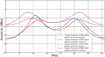
Finally, a further test has been performed in order to verify the capability of the proposed system to measure also the angular sensitivity of an RFID Tag by varying both θ and ϕ angles. In particular the commercial Tag Omni-ID Max-SQ-D, designed for on-metal applications, has been selected and tested in terms of angular sensitivity in two operative modalities: “on-air” (i.e. without any background material) and when applied on metal. In particular, a copper laminate having a size of 20 × 20 cm2 has been chosen as metal plane and used in this last case. In Fig. 5, angular sensitivity results obtained through the proposed system both by varying θ (blue lines) and ϕ (red lines) and related to the “on-air” case (dotted lines) as well as the “on-metal” one (continuous lines) are reported. First of all it can be observed that in both configurations the better performance is obtained with the tag facing the reader antenna (θ or ϕ around 0° and 360°) and the worst one with θ or ϕ around 90° or 270°. Moreover, a significant performance increase is obtained when the tag has been applied on the metal plate, with the tag sensitivity dropping from −8 to −18 dBm at 0°. This suggests that the Omni-ID Max-SQ-D tag has been designed by taking into account the background material, as expected.
Angular sensitivity by varying both θ and ϕ of an on-metal tag without any background material (dotted lines) and when applied to a metal plate (continuous lines).

Apart from the deductions related to the specific case, this test proves the ability of the proposed platform to measure the tag sensitivity also by varying θ and/or ϕ.
B) Performance evaluation of RFID tags applied on concrete blocks
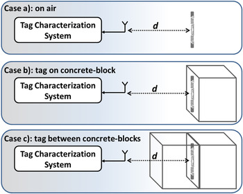
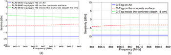
Once validated, a much more challenging test is performed, so to highlight the potentialities of the proposed RFID tag characterization system also in a possible use-case. More specifically, many applications require the integration of RFID tags into objects. Among them, the integration of tags into concrete-made structures or buildings could play a major role when autonomous vehicles or robots should need reference points from the environment. For such a reason, a selection of well-performing commercial RFID tags has been tested in three different working conditions, which are represented in Fig. 6(a) without any background material (on air), (b) applied on a concrete-block, and (c) between two concrete blocks. In Fig. 7(a), for instance, the results in terms of tag sensitivity in the European RFID band are reported for the Alien ALN-9640 tag. It is worth recalling that, as clear from (4), the lower is the tag sensitivity, the better is the tag performance. For this reason, it is confirmed that the ALN-9640 is a very well-performing tag for general purpose use. In fact, helped by the mounted higgs-4 chip characterized by a −20.5 dBm sensitivity, it exhibits a flat whole tag sensitivity of almost -18 dBm when air is used as background, corresponding to a reading range of more than 15 m. Despite this very good performance in the Case a) (see Fig. 5), the only presence of concrete in the background (Case b)) brings the sensitivity up to −9 dBm and even up to −3 dBm when the tag is between the two 15 cm-sided concrete cubes (case c)). Consequently, the application of the proposed characterization system confirmed that general purpose tags are not adequate for applications requiring tags immersed in concrete. In order to overcome such a problem, a new “concrete tag” (C-Tag) specifically tailored for these applications has been firstly designed by taking into account the presence of the concrete and by adopting the design strategy suggested in [Reference Catarinucci, Colella and Tarricone27], then realized with the method proposed in [Reference Catarinucci, Colella and Tarricone28], and finally tested with the proposed system. It is worth pointing out that the design has been done by considering a different RFID chip, the Impinj M3 with a sensitivity of only −15 dBm, so that a lower performance than the ALN-9640 is expected. Anyway, results reported in Fig. 7(b) deserve great interest. In fact, the performance drop measured when the tag is applied on the concrete surface is rather limited (from −9 to −4 dBm) and it is even smaller when the tag is immersed in the concrete.
Experimental setups for the tag characterization in/on concrete blocks.

(a) Tag sensitivity of both ALN-9640 and (b) C-Tag (b) for the three cases of Fig. 6.

Obtained results demonstrate that, regardless the simple analysis of commercial RFID tags placed on different materials or adopted in different working conditions, the proposed measurement system offers an important aid in designing RFID tags customized for specific applications.
V. CONCLUSIONS
In this paper, a cost-effective but accurate tool for performance analysis of UHF passive RFID tags has been presented. It is based on a commercial multi-programmable UHF RFID reader controlling a stepper motor and an appositely implemented software subsystem. In this way, it can perform the evaluation of the tag activation power threshold and, consequently, of tag sensitivity, working range and RP.
A validation campaign has been carried out on some commercial tags has been presented. A strong agreement with results obtained with commercial characterization platforms demonstrates the validity of the proposed solution. Moreover, results obtained by characterizing different tags applied on, and embedded into, concrete structures demonstrate the usefulness on the proposed system to be successfully used also in real application scenarios in which the support in selecting or designing RFID tags is crucial.
ACKNOWLEDGEMENTS
This work was supported in part by the TETRACOM Technology Transfer Project “TETRIS: TEchnology Transfer of RFID for Infrastructure Sensing”.
 Riccardo Colella received the M.Sc. degree (with honors) in Telecommunication Engineering in 2010 and the Ph.D. degree in Information Engineering in 2015 from the University of Salento, Lecce, Italy. Currently, he is a research fellow in the Electromagnetic Fields Group at the University of Salento. His main research interests are in the area of radio-frequency identification (RFID) technology with the design of novel RFID devices with augmented capabilities supporting the Internet of Things and novel techniques for RFID tag antenna prototyping and characterization. He authored about 70 papers that have appeared in international journals and at national and international conferences, two book chapters with international distribution, and a patent.
 Luca Catarinucci received the Laurea degree (with honors) in Electronic Engineering from the University of Perugia, Italy, in 1998. Since 2003, he has been with the University of Salento, Lecce, Italy, where he is currently an Assistant Professor of Electromagnetic Fields and Professor of Microwaves with the Department of Innovation Engineering. He authored more than 110 papers published in international journals and conferences and four chapters books with international diffusion. He holds two patents. His research activity has been mostly focused on the implementation of high-performance electromagnetic simulation tools, on the electromagnetic characterization of heterogeneous materials, on the use of time-domain reflectometry for the qualitative and quantitative characterization of fluids. Currently he is strongly involved in RFID-related activities, ranging from antenna and system design, integration between sensors and RFID tags, RFID-based robot navigation, and new techniques for tag characterization, optimization, and design. He is also responsible of the RFID division of the Electromagnetic Laboratory of the University of Salento.
 Luciano Tarricone received the Laurea degree (cum-laude) in Electronic Engineering and the Ph.D. degree from Rome University “La Sapienza,” Rome, Italy, in 1989 and 1994, respectively. Since 1994, he has been a Researcher at the University of Perugia, Italy, and since 1998, he has been a “Professore Incaricato” of EM fields and EM compatibility. Since November 2001, he is a Faculty Member with the Department of Innovation Engineering, University of Salento, Lecce, Italy, where he is Full Professor of Electromagnetic Fields. He has authored approximately 300 scientific papers. His main contributions are in the modeling of microscopic interactions of EM fields and biosystems, and in numerical methods for efficient computer-aided design (CAD) of microwave circuits and antennas. He is currently involved in bioelectromagnetics, EM energy harvesting and wireless power transmission, novel CAD tools and procedures for MW circuits, RFID, and EM high-performance computing.