Introduction
As demand for high-speed communications is constantly growing there are several proposals to build modules in the mm-wave spectrum. Frequency bands starting from 24 up to 65 GHz are receiving particular attention as they have potential for both high data rate communications and high-resolution radar applications. In near future transceivers covering a broad frequency band or switchable systems that can cover the mm-wave bands will be enabled [Reference Nawaz, Albrecht and Çağrı Ulusoy1]. In order for these transceivers to function there is a requirement for wideband antennas that can cover this wide bandwidth and at the same time have a reasonable gain and efficiency performance. The other solution would be to have multiple antennas catering to each individual frequency band, however this will require extra area in the module.
There have been studies going on to have a single antenna with an extremely wide bandwidth that can cover a wide frequency spectrum [Reference Novak, Miranda and Volakis2, Reference Moghaddam, Yang and Zaman3]. These require multiple via connections with multilayer printed circuit boards and are for broad side applications. In this work, an end fire antenna on a flexible substrate is proposed. Typically, end fire antennas for mm-wave applications are based on dipole and folded slot antennas [Reference Park, Seong, Whang and Hong4–Reference Harle, He and Papapolymerou6]. However, they have narrow bandwidth. 3D antennas can solve the bandwidth requirements as investigated in [Reference Ahmad and Hesselbarth7–Reference Ahmad and Hesselbarth9] but the drawback is they can occupy more space and are relatively rigid in nature.
To address the above-mentioned issues a wideband Vivaldi antenna is investigated in this work. These kinds of antennas are very broadband in nature and can cover extremely wide bandwidths.
Antenna concept
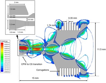
As a first step, a conventional Vivaldi antenna was simulated with a differential port. Flexible Ultralam 3850 and Polymide thin film were used as a substrate for this antenna. The antenna performance is optimized for a wide frequency band and gain performance. The antenna is designed to cover the frequency band of 25–65 GHz; therefore, it can cover the frequency range for the frequency bands allocated for 5G. Corrugations on the arms are added to increase the directivity of the antenna. As a next step a coplanar waveguide (CPW) to coplanar stripline transition was designed in order to probe the antenna with a ground-signal-ground (GSG) probe [Reference Anagnostou, Morton, Papapolymerou and Christodoulou10]. Alternatively, a ground-signal probe can be used to feed the antenna. Antenna has a total length of 15 mm and a flare opening of 11.5 mm. Figure 1 shows the dimension of the antenna along with the electric field plot on the surface of the antenna.
Top view of the printed Vivaldi antenna with E-field distribution across the structures and dimensions.

As mentioned earlier the main motivation of designing this antenna is to have a wideband performance for the upcoming 5 G systems. However, integrating the antenna with a wideband transceiver is also a big challenge as the typical chip integration approaches such as bond wire and solder bump are typically working for low frequencies and show a narrow band performance when compensation networks are introduced.
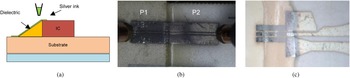
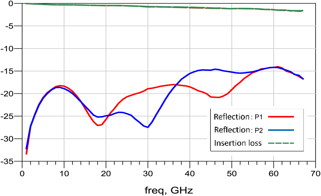
To solve this integration issue, a ramp transition was introduced from a dummy chip. These kinds of transitions have the potential to provide a wide bandwidth over the other conventional solutions [Reference Qayyum, Abt, Roch, Ulusoy and Papapolymerou11]. Figure 2(a) shows the transition concept where a chip can be placed on a substrate and a ramp can be made with a dielectric material starting from the edge of the chip to the substrate. Once the ramp is made, an aerosol jet printer can be used to print the conductive lines connecting the chip to the laminate. Figure 2(b) shows the ramp interconnect measured with a GSG probe. A laminate is used instead of chip for demonstration purposes. The measured reflection and insertion loss of this structure are shown in Fig. 3. The measurements show that this ramp interconnect can cover the mm-wave band up to 65 GHz without any matching networks. As this transition covers the mm-wave range the antenna can be integrated with such a transition. Figure 2(c) shows the antenna integrated with a ramp interconnect. A Polytec TC 430-T thermal adhesive was used as a ramp structure which was deposited by syringe. Once the adhesive is thermally cured, silver nano particle ink CPW lines are printed and sintered. Sixty percent of bulk conductivity of silver is obtained for the printed lines.
Coplanar waveguide (CPW) transition over the ramp structure. (a) Ramp transition concept. (b) Ramp fabricated with printed silver coplanar waveguide (CPW) lines. (c) Antenna integrated with the ramp transition.

Measured reflection and insertion loss of the ramp structure (see Fig. 2 (b)).

Antenna characteristics
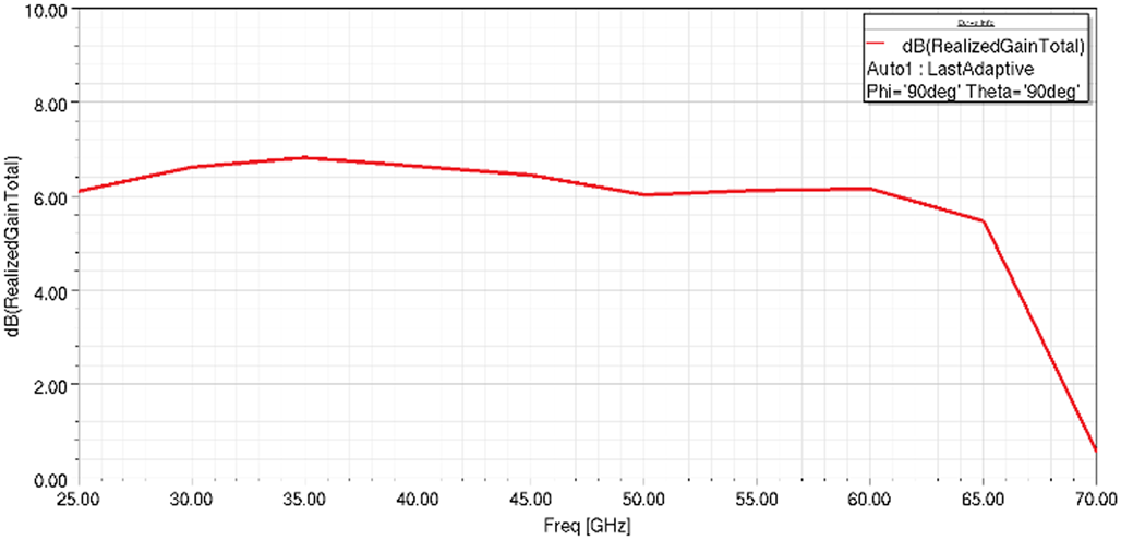
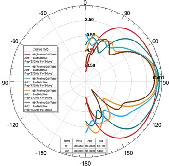
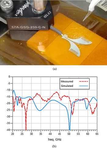
The antenna when integrated with a ramp transition shows a wide bandwidth performance. The simulated gain performance of the antenna is shown in Fig. 4. The gain of the antenna remains above 5 dBi for the frequency range of 25–65 GHz. The radiation pattern of the antenna is shown in Fig. 5 for 25–65 GHz with 10 GHz increment. The reflection of the antenna is measured with a GSG probe which is calibrated up to the probe tips with a Short, Open Load, Thru calibration kit. The setup is shown in Fig. 6. Measured and simulated S-parameters of the antenna are also shown in Fig. 6. The reflection remains under −10 dB for the frequency band of 25–65 GHz.
Simulated gain performance of the antenna.

Simulated radiation pattern of the antenna at 25, 35, 45, 55, and 65 GHz.

Measurement of the antenna. (a) Ground-signal-ground (GSG) measurement setup. (b) Simulated versus measured reflection of the antenna.

Conclusion
The design of a wideband Vivaldi antenna is presented in this work with a wideband interconnect concept. This provides a solution for a radiator to cover the millimeter-wave spectrum from 25 to 65 GHz. The main advantage of this approach is that wideband or switched transceivers for future 5 G communications can be integrated using this concept without the need of complex matching networks.
 Zunnurain Ahmad (S'17) received his Ph.D. degree in electrical engineering from University of Stuttgart, Germany. His current research interests include high efficiency 3-D antennas for millimeter wave applications and interconnect.
 Lee Harle (S'97–M'03) received her B.S. degree in physics from Indiana University, Bloomington, in 1996, and the M.S.E. and Ph.D. degrees in electrical engineering from The University of Michigan at Ann Arbor, in 1998 and 2003, respectively. Her thesis focused on micromachined cavity resonator filters in silicon.