Introduction
The Internet of Medical Things (IoMT) has experienced remarkable advancements, becoming a cornerstone in revolutionizing healthcare through efficient medical data transmission. Wireless communication technologies enable sensor nodes, strategically placed on the human body, to monitor vital signs. These sensors use protocols operating across frequency bands, including Bluetooth/Zigbee/WiFi in the 2.45 band, and 5G in both sub-6 GHz and millimeter wave bands. Additionally, LoRaWAN, operating in license-free ISM bands is gaining prominence for long-range, low-power medical Internet of Things (IoT) applications. Its license-free operation allows cost-effective deployment making it ideal for remote healthcare monitoring. The 3 GHz spectrum within the sub-6 GHz range also stands out for its balance of coverage, bandwidth, and low latency that are essential for medical IoT. Antennas are fundamental to the success of these systems, ensuring seamless data transmission across various frequency bands reducing signal loss, and enhancing energy efficiency. Their design and placement are crucial for optimizing the performance of medical IoT systems contributing to improved patient outcomes and a more connected healthcare ecosystem.
In literature, several antennas for on-body communications have been reported to support information technology. The design demands a highly flexible substrate, such as felt, textile, or other soft materials, to ensure comfort and conformability to the human body [Reference Khan, Sethi, Malik, A, Khalid, Almuhlafi and Himdi1]. While these substrates are commercially available, the fabrication of antennas in these materials is a challenging task owing to the non-suitability of the conventional photolithography process. To overcome this problem, a highly flexible polyimide material is chosen in this research to demonstrate the design and development of a conformal antenna for Wireless Body Area Network (WBAN).
A dual-port antenna with shorting annular ring resonator surrounded by substrate-integrated waveguide is presented in paper [Reference Mirhadi2] for operation at 5.8 GHz. An all-textile antenna functioning at 2.45/5.8 GHz and the IEEE 802.16 2005 band is reported in paper [Reference Li, Du, Yang and Gao3] using denim substrate. The reported antenna having a footprint of 60 × 60 mm exhibits negative gain characteristics. A pattern reconfigurable dual-mode antenna operating at 2.45 GHz with 3.8% fractional bandwidth (FBW) is demonstrated in paper [Reference Gao, Zhang, Dong, Dou, Yu and Hu4]. An optimized wearable antenna with slots and multi-resonant structures is described in paper [Reference Samal, Chen and Fumeaux5] for operation in 2.45 and 5.8 GHz frequency bands with an averaged maximum gain of 7.2 dBi. A combination of flexible polydimethylsiloxane and PF4-foam is used as a hybrid substrate to develop a wearable antenna with broadside radiation at 2.45 GHz and omnidirectional radiation pattern at 5.8 GHz spectrum is detailed in paper [Reference Samal, Chen and Fumeaux6]. The research in paper [Reference Musa, Shah, Majid, Mahadi, Rahim, Yahya and Abidin7] presents a dual-band wearable antennaoperating at 2.45 and 5.8 GHz with an FBW of 3.75% and 5.17%, respectively. An antenna for monitoring vital signs is presented in paper [Reference Waly, Smida, Bakouri, Alresheedi, Alqahtani, Alonzi and Smida8] for operating at 868 and 915 MHz LoRa bands. The antenna is characterized by a small gain of 2.12 dBi. The meta-surface inspired Multiple-Input Multiple-Output (MIMO) antenna in paper [Reference Althuwayb, Alibakhshikenari, Virdee, Rashid, Kaaniche, Atitallah, Armghan, Elhamrawy, See and Falcone9] operates from 5.0 to 6.0 GHz with an improved isolation of over 34 dB. A biopolymer substrate is utilized in paper [Reference Sid, Cresson, Joly, Braud and Lasri10] to develop a dual-band antenna operating at 2.45 and 5.8 GHz. The researchers in paper [Reference Noghanian11] has proposed a WiFi sensing antenna with rectangular geometry developed over denim material operating at 2.45 and 5.5 GHz. A defected ground structure–based advanced wireless systems antenna operating from 2.106 to 2.214 GHz and further covering 4.141–4.362 GHz is reported in paper [Reference Rao and Konkyana12]. The dual-band textile antenna for on-body and off-body communications described in paper [Reference Sharma, Kumar, Tiwari, Choi and Kim13] covers the 5G n79 frequency bands for WBAN communications. A triple-frequency antenna covering the C band, X band and Ku band frequencies are discussed in paper [Reference Ayyappan, Arulappan and Raj14]. A double-T-based sub-6-GHz antenna for fifth-generation smartphone applications in paper [Reference Jaglan, Gupta, Kanaujia and Sharawi15]. In paper [Reference Jaglan, Gupta and Sharawi16], the researchers presented the design of an 18-element MIMO antenna covering the fourth- and fifth-generation communication frequencies for smartphone applications. In addition to the development of ultra-wideband antenna with MIMO implementation, research has also been conducted to produce rejection within the operating bandwidth of the antenna as detailed in paper [Reference Naveen, G, Thakur, Kumar, Kanaujia and Srivastava17]. Many other multiband antennas with MIMO configuration has been reported in literature [Reference Kumkhet, Wongsin, Sangmahamad, Thaiwirot, Mahatthanajatuphat and Chudpooti18–Reference Kang, Tak and Choi22].
Thus, the recent research on wearable antennas for WBAN applications has shown significant progress, with dual-band characteristics. The conformal antenna is essential for the proposed IoMT and 5G-enabled WBAN scenario due to its flexibility, reliability, and suitability for wearable applications. Multiband antennas with MIMO configurations with high isolation are explored for enhanced performance in on-body scenario. However, a key research gap lies in optimizing antenna profile thickness, size, gain and coverage while maintaining low power consumption and minimizing mutual coupling for reliable performance for diverse healthcare applications. This article describes an eight-element MIMO antenna scheme with good FBW and gain characteristics. The realized antennas in the MIMO scheme have FBW more than 8% in both operating bands ensuring higher throughput. Further MIMO parameters are calculated and described for the eight-element MIMO scheme. The “Antenna design and development” section provides a details of the antenna geometry and the proposed MIMO scheme. The “Fabrication and measurement” section outlines the results and discussions. In the “Evaluation of diversity metrics” section, the diversity performance metrics are discussed. Finally, the “State-of-the-art comparison” and “Conclusion” sections describe the state-of-the-art comparison and concludes the research, summarizing the key findings respectively.
Antenna design and development
Geometry
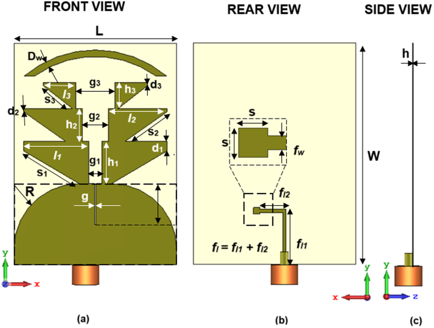
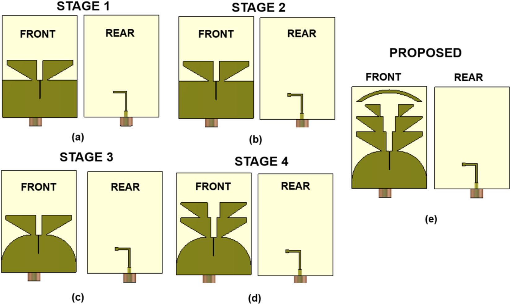
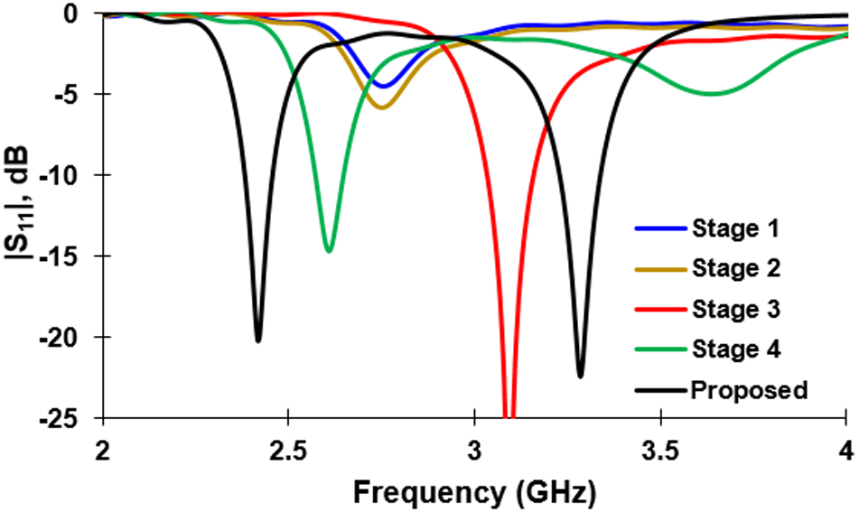
The proposed dual-band quasi-Yagi radiator is illustrated in Fig. 1. The antenna design is attempted to address the requirements of IoMT applications, where reliable on-body communication is critical. The proposed quasi-yagi radiator is designed on a polyimide material. The dielectric constant is 3.5, while the power loss tangent is 0.0023. The substrate thickness of 50 µm ensures excellent flexibility and conformal properties suitable for on-body antennas. The choice of polyimide material for the proposed conformal antenna is driven by its exceptional flexibility, low dielectric loss, and mechanical durability, making it ideal for wearable and body-mounted applications in IoMT and WBAN environments. The polyimide material is copper-clad on both sides, and the copper layer is patterned to make it frequency dependent while the rear side is patterned to offer the excitation line. The antenna during the developmental stages is detailed in Fig. 2. The corresponding S-parameters at various stages of development are described in Fig. 3. The simulations are performed in the frequency domain solver of Computer Simulation Technology Software with accuracy set to 10−6.
Proposed wedge-shaped dual band antenna (a–c) different views.

The design begins with a dual-radiating arm design, as illustrated in Fig. 2(a). These radiating arms are wedge-shaped, with the total length of the radiators (2l1 + g1) chosen to be approximately half a wavelength at 3.4 GHz. The radiator on the top is fed by an L-shaped feedline, which transfers microwave energy through a narrow slot line, as shown in Fig. 2(a). The initial design’s bandwidth performance is constrained by the antenna’s profile thickness. To address this limitation, several strategies are implemented to enhance bandwidth properties.
Developmental stages of the antenna: (a) basic radiator, (b) feedline terminated with square patch, (c) ground modified radiator, (d) modified radiating arms, and (e) proposed antenna.

First, an L-shaped feed transmission line is used as a feed to improve the antenna’s reflection coefficient bandwidth. The antenna in Fig. 2(a) exhibits resonant characteristics, as depicted in Fig. 3. Impedance matching at the spot frequency is further enhanced by introducing a square patch termination in the L-shaped feedline as in Fig. 2(b). Although this alteration strengthens the impedance matching, the antenna’s performance remains below acceptable levels. To overcome this limitation, modifications are made to the ground as in Fig. 2(c). The ground conductor is shaped and blended with a radius “R” to achieve optimal matching conditions. This adjustment produces a resonance around 3.15 GHz with |S11|min ≤ −35 dB. The primary research objective is to achieve dual-band resonance. To this end, the number of wedge-shaped resonators is increased progressively from one to two and then to three, as shown in Fig. 3. Adding two wedge-shaped radiators, as depicted in Fig. 2(d), introduces dual-band resonance characteristics, albeit with a weak resonant mode at the upper frequency. The impedance matching is further improved by incorporating a third pair of wedge-shaped radiating arms and a semicircular director, as shown in Fig. 2(e). This final antenna geometry successfully achieves the desired dual-frequency characteristics, providing FBWs of 8.16% and 8.59%, respectively. These dual-frequency bands meet the bandwidth requirements for the transmission of medical data. Table 1 summarizes the optimized geometrical parameters of the wedge shaped quasi-Yagi antenna.
|S11| characteristics of the wedge shaped quasi-Yagi antenna.

Optimized antenna parameters (unit millimeter)

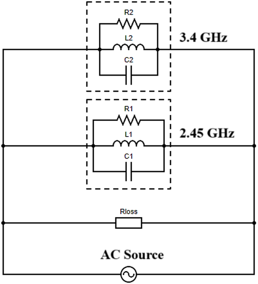
The operation of the proposed dual-band antenna is further illustrated with a help of an equivalent circuit diagram. The equivalent circuit of the proposed antenna described in Fig. 4 consists of two parallel resonant circuits (R1-L1-C1 and R2-L2-C2) indicating the resonant frequencies 2.45/3.4 GHz of the Yagi-Uda antenna with wedge shaped radiators. The losses associated with the antenna are represented by R loss. The antenna is connected to an excitation source as shown in Fig. 4. By effectively adjusting the values of L1-C1 and L2-C2, the resonant frequencies of the proposed dual-band antenna can be controlled. The inductance (L n) in the equivalent circuit is primarily due to the effective current path length of the wedge-shaped radiator, which influences the antenna’s resonant frequency. A longer path increases L n, lowering the resonant frequency, while a shorter path reduces L n, shifting the resonance higher. The capacitance (C n) arises from the gap and spacing between the radiator and the ground plane, as well as the coupling between the parasitic director elements in the Yagi configuration. A smaller gap results in higher capacitance, which helps in impedance matching and bandwidth control. Together, L n and C n govern the dual-band resonance, ensuring efficient radiation and frequency selectivity for 2.45 and 3.4 GHz operations.
Equivalent circuit model for the proposed dual-band antenna.

Development of MIMO antenna
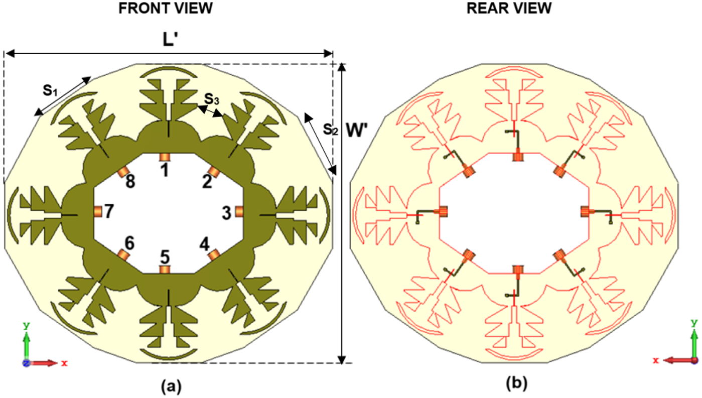
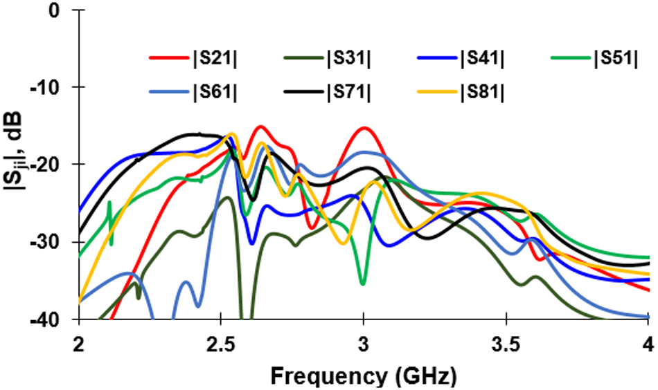
Building upon the proposed antenna, a multi-element scheme is developed to enhance communication performance, particularly for applications in on-body communications and IoMT. The MIMO configuration shown in Fig. 5 replicates the same wedge-shaped radiators and structural modifications discussed earlier, with 10 mm edge-to-edge separation. The total area of the proposed eight-element scheme is 125 mm × 115 mm, ensuring a compact footprint suitable for wearable and body-mounted devices. The antenna elements are distributed along the edges to form an octagonal arrangement, which optimizes spatial diversity and minimizes mutual coupling. The design features a connected ground scheme, which inherently provides mutual coupling less than −15 dB between elements as shown in Fig. 6, eliminating the need for additional electromagnetic structures to suppress mutual coupling. The central portion of the antenna structure is designed as an octagonal free space, allowing for the routing of cables or other components without interfering with the antenna’s radiation performance. This geometric distribution not only achieves the desired dual-band operation but also supports the reliable transmission of medical data across multiple channels. The compact size, dual-band characteristics, and robust performance in close-proximity scenarios make this design highly relevant for IoMT applications for real-time medical data transmission.
Eight-element MIMO antenna (a and b) different views. The red lines in (b) indicate the shape in the front side.

Mutual coupling characteristics with Port 1 as reference.

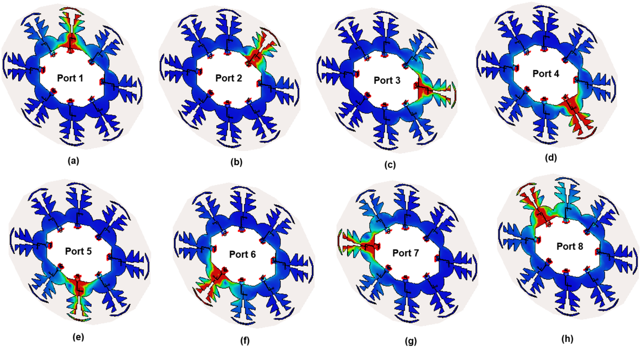
The surface current contour, as illustrated in Fig. 7, demonstrates the independent operation of each antenna element, ensuring minimal interference and strong performance. When a specific antenna element is excited, the surface current is highly concentrated along its radiating arms, feedline, and ground plane. This localized current concentration ensures optimal radiation and impedance matching for the excited antenna. In contrast, the neighboring antenna elements exhibit negligible current strength, which confirms the low mutual coupling achieved by the design. This behavior is primarily due to the connected ground scheme and the strategic octagonal distribution of the elements, which effectively decouples the radiating fields of adjacent antennas. The minimal interaction between antenna elements ensures that each operates independently, preserving the integrity of the MIMO scheme and enabling reliable dual-band performance for IoMT applications. This intrinsic isolation is critical for maintaining consistent signal quality and efficient data transmission in multichannel communication systems.
Surface current distribution during the excitation of different ports in the MIMO scheme at 2.45 GHz. (a–h) Excitation of Ports 1–8.

Fabrication and measurement
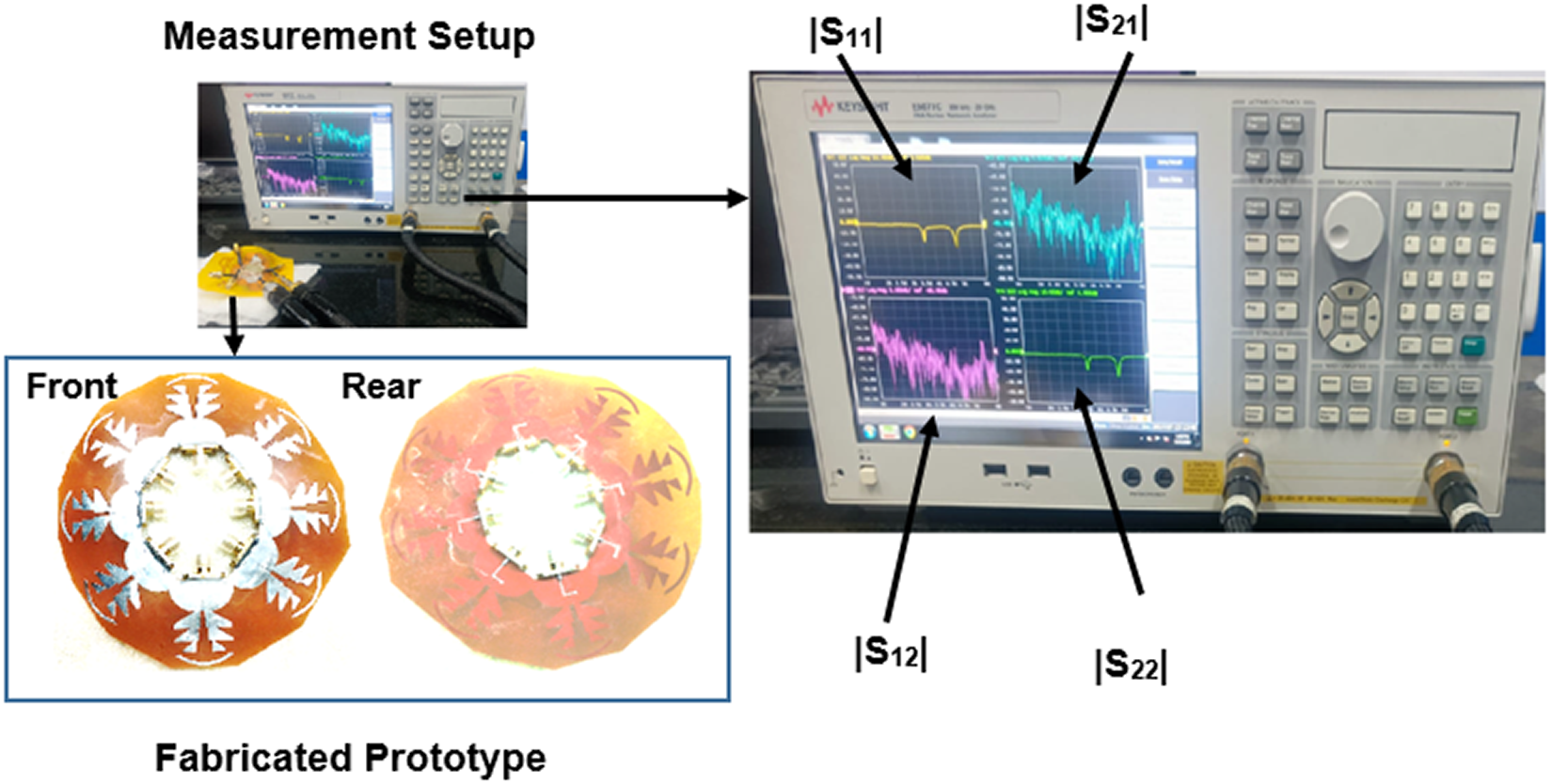
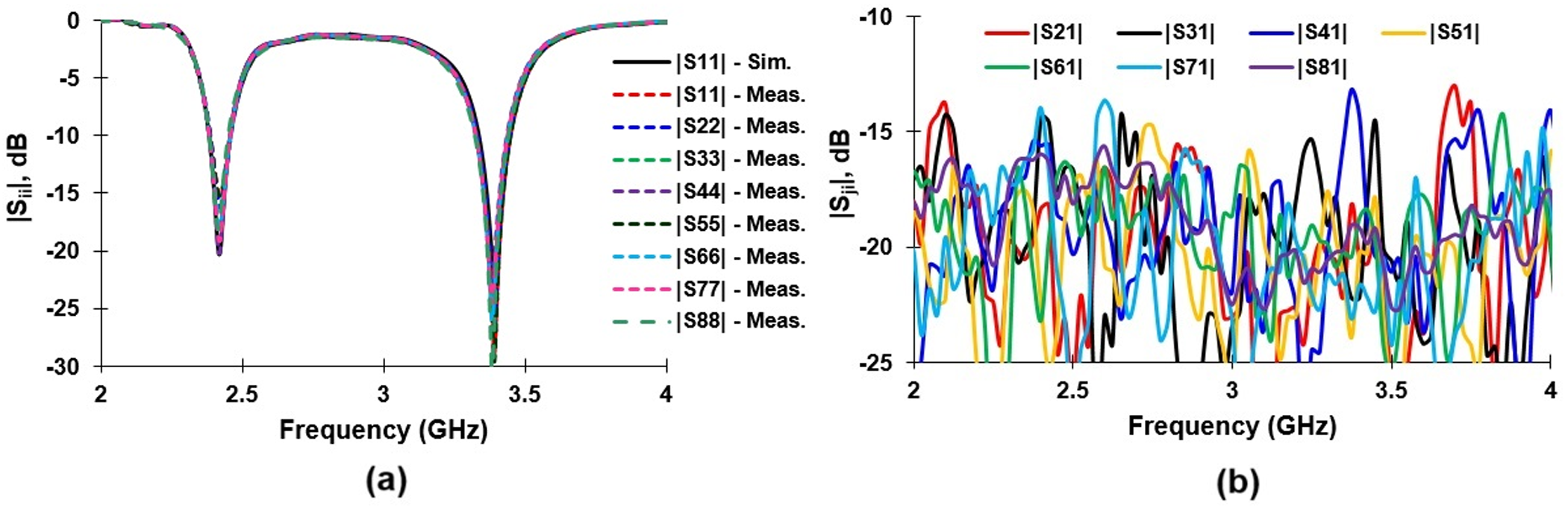
The prototype MIMO antenna is fabricated using the conventional printed circuit board (PCB) manufacturing process. The performance of the antenna in real-time is verified using real-time measurements. The measurement is conducted using Keysight E5071C Vector Network Analyzer. N4432D electronic calibration kit from Keysight Technologies is used for fine calibration. The prototype antenna is manufactured using photo-etching method. The developed antenna in the measurement environment is shown in Fig. 8. The fabricated prototype pictures are described in the inset of Fig. 8. The measurement S-parameters of the proposed eight-element antenna is illustrated in Fig. 9(a) and (b). The measured reflection and transmission coefficients are in close correlation with the simulation results as evidenced through Fig. 9. The measured FBW of the antenna is more than 8% in both the lower frequency and upper frequency band centered at 2.45 and 3.4 GHz, respectively. The mutual coupling characteristics described in Fig. 9(b) shows a strong decoupling between the ports of the eight-element antenna. In all the port combinations, the inter-port isolation is greater than 15 dB in both frequency bands.
Measurement setup showing the fabricated prototype and the measurement window.

(a) Reflection coefficient characteristics. (b) Mutual coupling characteristics.

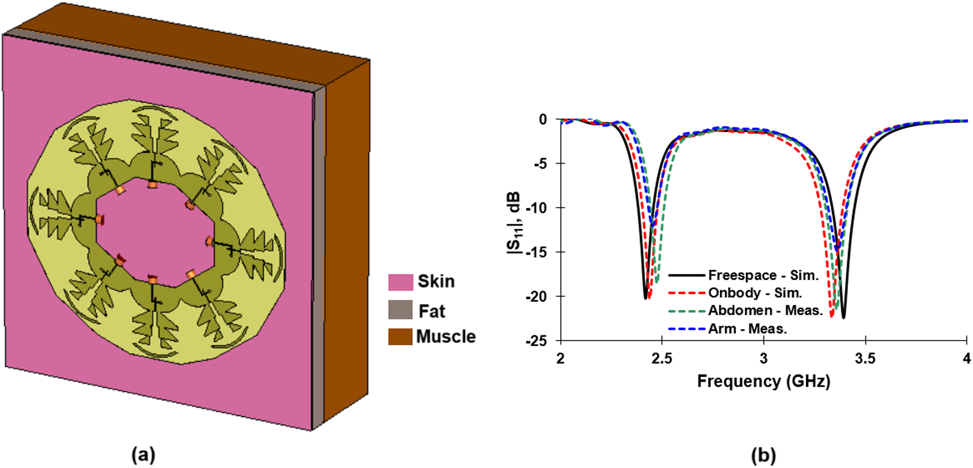
The prototype antenna is also measured in the presence of human body to validate its performance for WBAN applications. The simulated and measured on-body performance of the antenna is illustrated in Fig. 10. During simulations, a three-layer human body model is used for the simulations. The layer consists of skin (εr = 38; σ = 1.46 S/m), fat (εr = 10.8; σ = 0.268 S/m) and muscle (εr = 52.7; σ = 1.74 S/m) as shown in Fig. 10(a). The thickness of each layer is fixed as 1 mm, 5 mm and 100 mm respectively and the simulation analysis is carried out. The simulated and measured reflection coefficient characteristics are presented in Fig. 10(b). In order to retain the original characteristics of the antenna, the antenna and the human body are separated by a distance of 1 cm using foam material. In reality, the antenna will be positioned on a platform whose base is at least 1 cm thick holding the PCB with necessary electronics. This arrangement reduces the direct interaction of the human body with the antenna. In line with this, the spacing between the antenna and the human body is chosen as 1 cm. Further, for the sake of experiment, a female subject of age 37 is chosen. The antenna is located on the abdomen region where the antenna is maximally flat and in the arm region where the antenna undergoes some bending effects. In both the cases, the antenna exhibited dual-band response with a slight frequency shift. However, under flat and bent conditions, the required bandwidth specification to perform medical information exchange is satisfied making the antenna suitable for WBAN communications.
(a) On-body simulation setup. (b) Reflection coefficient characteristics.

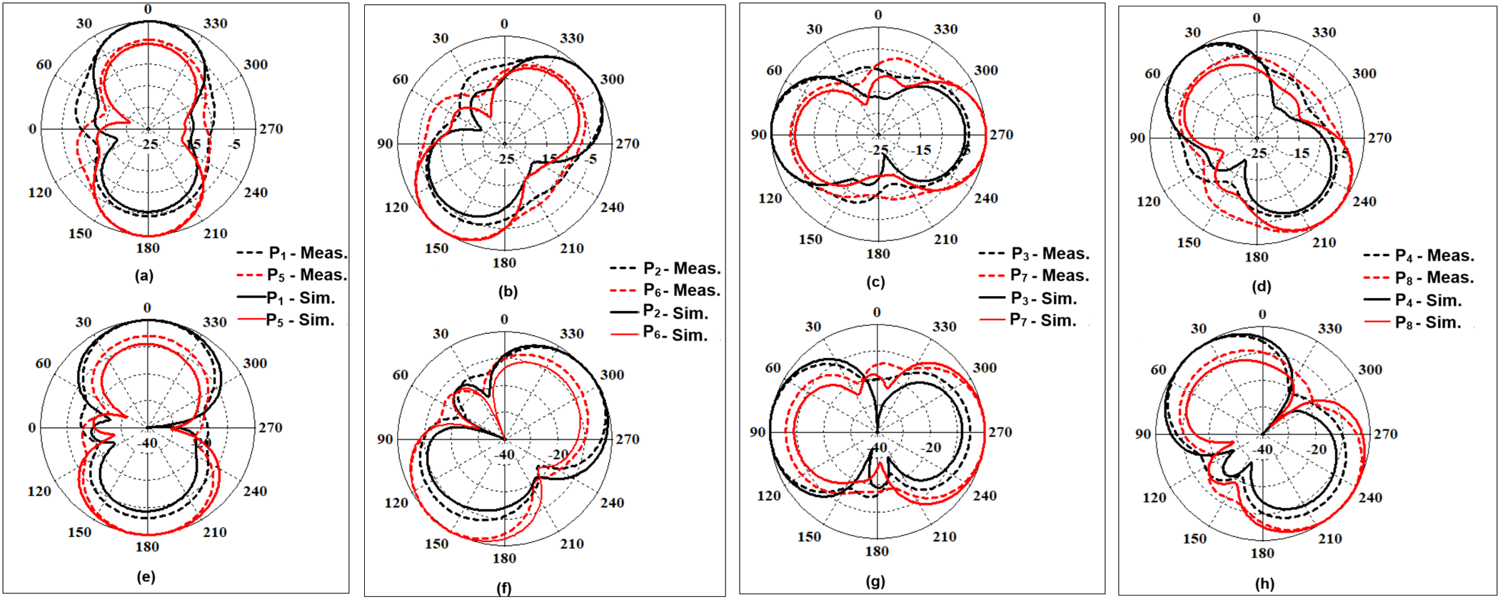
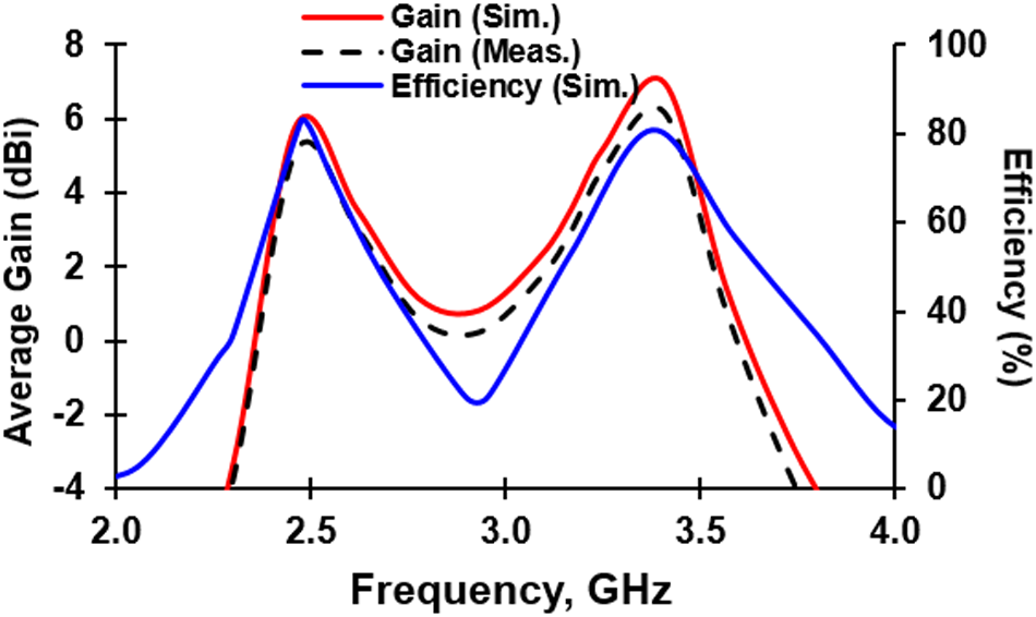
The antenna radiation pattern is measured in an anechoic chamber and the estimated radiation patterns in simulation and measurement are depicted in Fig. 11. The proposed eight-element antenna array exhibits unidirectional radiation pattern along specific direction. The port pairs producing oppositely directed radiation patterns are Ports 1–5, Ports 2–6, Ports 3–7, and Ports 4–8. Thus, the proposed scheme offers pattern diversity connecting to different sensor elements deployed along the surface of the human body. The peak measured gain of the antenna is 5.72 dBi at 2.45 GHz and 6.13 dBi at 3.4 GHz. The simulated peak antenna efficiency is greater than 80% in both the realized frequency bands. A plot of antenna gain, efficiency versus the frequency is described in Fig. 12.
Normalized radiation pattern: (a)–(d) At 2.45 GHz. (e)–(h) At 3.4 GHz.

Gain/efficiency versus frequency behavior of the MIMO radiator.

Evaluation of diversity metrics
The MIMO/diversity metrics is analyzed to validate its suitability for IoMT and 5G applications. Standard equations, as referenced in paper [Reference Sharawi23], are employed to calculate key parameters of the MIMO scheme. These calculations show the MIMO scheme’s capability to deliver high performance in terms of gain, diversity, and reliability, ensuring efficient communication for on-body sensor networks.
 \begin{equation}{\rho _e} = \frac{{|\iint {\left( {\mathop {\mathop F\nolimits_1 }\limits^ \to (\theta ,\phi ) \bullet \mathop {\mathop F\nolimits_2 }\limits^ \to (\theta ,\phi )} \right)d\Omega }{|^2}}}{{\iint {|\mathop {\mathop F\nolimits_1 }\limits^ \to (\theta ,\phi ){|^2}d\Omega \iint {|\mathop {\mathop F\nolimits_2 }\limits^ \to (\theta ,\phi ){|^2}d\Omega }}}}\end{equation}
In Equation (1), the field components (F 1 and F 2) along the 3D planes are utilized to assess the Envelope Correlation Coefficient (ECC) of the diversity scheme for different port combinations in the eight-element MIMO antenna. The Apparent Diversity Gain (ADG) is evaluated using the ECC through Equation (2).
 \begin{equation}{G_{app}} = 10 \times \sqrt {1 - \left| {{\rho _e}} \right|} \end{equation}
To evaluate the actual diversity performance of the eight-element dual-band MIMO radiator, the losses associated with the radiation are factored into the ADG as outlined in Equation (3) and specified as Effective Diversity Gain (EDG).
 \begin{equation}{G_{eff}} = {\eta _{total}} \times {G_{app}} = {\eta _{total}} \times 10 \times \sqrt {1 - \left| {{\rho _e}} \right|} \end{equation}
The Mean Effective Gain (MEG) determines the overall gain characteristics in the context of a multi-antenna system. The evaluation of MEG takes into account the cross-polarization ratio (XPR) as given in Equation (4). For isotropic conditions, the XPR is assumed to be 0 dB, implying ideal conditions with no polarization discrimination. In more realistic settings, the XPR is adjusted to 1 dB for indoor environments, where walls and other obstacles can affect signal polarization, and 5 dB for outdoor scenarios, where environmental factors such as buildings and foliage can introduce more significant polarization effects. Additionally, normal power distribution, with µ and σ of 10° are assumed during the calculation. This assumption accounts for the typical variation in signal propagation and antenna alignment, reflecting realistic conditions in both indoor and outdoor environments. By incorporating these factors, the MEG calculation ensures a comprehensive and accurate assessment of multi-antenna system performance for effective design suitable for real-world applications.
 \begin{equation}MEG = \int\limits_0^{2\pi } {\int\limits_0^\pi {\left[ \begin{gathered}
\frac{{XPR}}{{1 + XPR}}{G_\theta }(\theta ,\phi ){P_\theta }(\theta ,\phi ) \hfill \\
+ \frac{1}{{1 + XPR}}{G_\phi }(\theta ,\phi ){P_\phi }(\theta ,\phi ) \hfill \\
\end{gathered} \right]} } \sin \theta d\theta d\phi \end{equation}
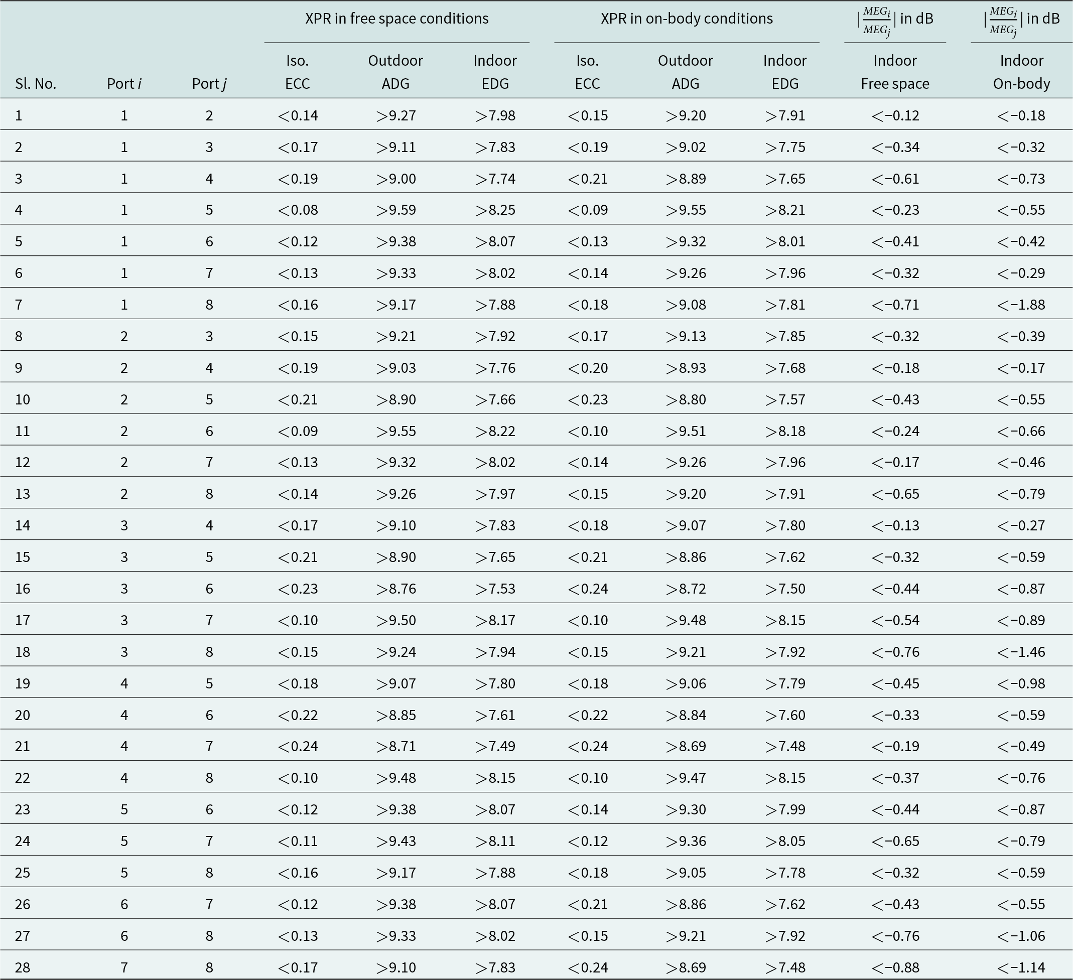
The estimated MIMO metrics for different scenarios (Isotropic (XPR = 0 dB); Indoor (XPR = 5 dB) and Outdoor (XPR = 1 dB)) are presented in Table 2. The far-field based ECC is significantly below 0.25 ensuring minimal correlation between antenna elements and excellent isolation. The ADG and EDG values are above 7.4, demonstrating the antenna’s ability to maintain high diversity performance under varying conditions. Additionally, the ratio of MEG is substantially lesser than −0.6 dB, further confirming the efficient gain characteristics of the proposed antenna system. These results highlight the effectiveness of the design in supporting reliable and robust MIMO performance, making it desirable for high throughput communications such as IoMT and 5G wireless communication.
MIMO performance parameters at 2.45 and 3.4 GHz using measurement data

State-of-the-art comparison
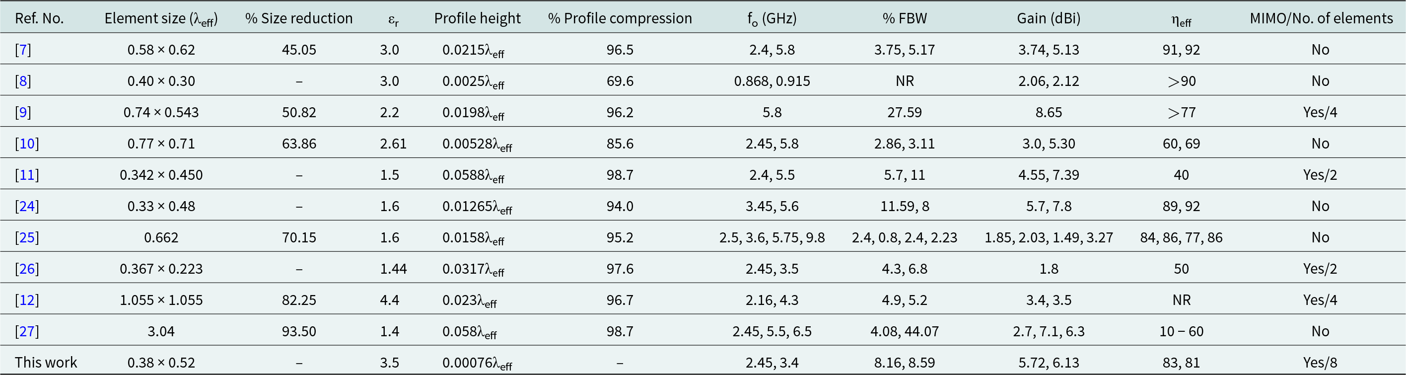
The proposed dual-band conformal antenna is compared with the existing dual-band MIMO antennas particular used from MIMO applications. Table 3 presents the detailed comparison of the quasi-Yagi antenna.
Comparison with the state-of-the-art

The following are the inferences derived from the Table 3:
1. The proposed antenna has an element size of 0.38λeff × 0.52λeff, which is smaller than many other designs, such as those in papers [Reference Musa, Shah, Majid, Mahadi, Rahim, Yahya and Abidin7, Reference Althuwayb, Alibakhshikenari, Virdee, Rashid, Kaaniche, Atitallah, Armghan, Elhamrawy, See and Falcone9, Reference Sid, Cresson, Joly, Braud and Lasri10, Reference Adam, Rahim, Yasin and Nasrol21, Reference Sharawi23, Reference Saeidi, Al-Gburi and Karamzadeh24].
2. The proposed antenna has an extremely low profile height of 0.00076λeff, much lower than other designs reported in papers [Reference Musa, Shah, Majid, Mahadi, Rahim, Yahya and Abidin7–Reference Noghanian11, Reference Rajawat, Mohta, Sharma and Gupta20–Reference Saeidi, Al-Gburi and Karamzadeh24]. This makes the proposed antenna highly suitable for wearable and space-constrained applications.
3. The antenna reported in this research operates at 2.45 and 3.4 GHz, with FBW of 8.16% and 8.59%, which is higher than many other antennas reported in papers [Reference Musa, Shah, Majid, Mahadi, Rahim, Yahya and Abidin7, Reference Sid, Cresson, Joly, Braud and Lasri10, Reference Adam, Rahim, Yasin and Nasrol21–Reference Sharawi23]. Although paper [Reference Althuwayb, Alibakhshikenari, Virdee, Rashid, Kaaniche, Atitallah, Armghan, Elhamrawy, See and Falcone9] offers higher FBW, the proposed work maintains a balance between FBW and compactness.
4. The reported antenna provides 5.72 and 6.13 dBi of gain, which is comparable to papers [Reference Althuwayb, Alibakhshikenari, Virdee, Rashid, Kaaniche, Atitallah, Armghan, Elhamrawy, See and Falcone9] and [Reference Adam, Rahim, Yasin and Nasrol21]. While paper [Reference Althuwayb, Alibakhshikenari, Virdee, Rashid, Kaaniche, Atitallah, Armghan, Elhamrawy, See and Falcone9] offers a higher peak gain, the proposed antenna achieves a good balance between gain and efficiency, which is higher than many others antennas [Reference Althuwayb, Alibakhshikenari, Virdee, Rashid, Kaaniche, Atitallah, Armghan, Elhamrawy, See and Falcone9, Reference Sid, Cresson, Joly, Braud and Lasri10, Reference Adam, Rahim, Yasin and Nasrol21, Reference Kang, Tak and Choi22, Reference Saeidi, Al-Gburi and Karamzadeh24].
5. The proposed antenna is replicated to implement an 8 elements for MIMO, which is the highest number of elements in this comparison, outperforming papers [Reference Althuwayb, Alibakhshikenari, Virdee, Rashid, Kaaniche, Atitallah, Armghan, Elhamrawy, See and Falcone9] and [Reference Noghanian11]. Thus, the proposed solution has a significant advantage in terms of data throughput and communication reliability.
In summary, the proposed dual-band eight-element MIMO antenna has attractive properties such as small element size and highly compresses profile height, large FBW, good gain and efficiency with enhanced channel capacity. These aspects make it highly suitable for modern applications like 5G, WBANs, and wearable devices, especially when compared to other designs that may prioritize larger size or fewer MIMO elements.
Conclusion
This work presented a flexible and conformal dual-band quasi-Yagi antenna designed for IoMT and WBAN applications, offering stable performance on the human body. The use of polyimide material ensures mechanical flexibility, while the wedge-shaped quasi-Yagi radiator achieves dual-band resonance at 2.45 and 3.4 GHz. The antenna’s optimized ground plane, microstrip-to-slot transition, and arc-shaped director contribute to improved impedance matching, gain, and directionality. The single-element antenna demonstrates high efficiency (∼80%) and wideband characteristics, making it suitable for wearable healthcare applications. Furthermore, the MIMO extension, with an eight-element configuration, enhances spatial diversity, reduces mutual coupling (<−15 dB), and ensures robust multi-channel communication. The proposed antenna effectively meets the demands of modern wireless medical communication, offering a compact, efficient, and scalable solution for real-time biomedical data transmission in 5G-enabled IoMT networks. The proposed antenna is ideal for healthcare, telemedicine, and military use, which ensures robust connectivity but requires precise fabrication and may need relay nodes for extended coverage.
Data availability statement
No new data generated for the execution of this research.
Author contributions
Suganyadevi Subramani – Concept, Simulation, Paper writing and Journal correspondence; Ramesh Subramaniam – Supervision, Paper revision
Funding statement
No funding was received for this research.
Competing interests
There is no conflict of interest with respect to this submission.

Suganyadevi Subramani received her B.E. in Electronics and Communication Engineering from Anna University, Chennai, in 2011, and her M.E. in Communication Systems from Anna University, Chennai, in 2016. She is currently pursuing full-time Ph.D. in the department of Electronics and Communication Engineering at SRM Valliammai Engineering College affiliated to Anna University, Chennai. Her research focuses on antennas, medical electronics, wireless sensor networks, energy efficiency, and energy harvesting. With a strong academic foundation and a passion for innovation, she aims to address critical challenges in wireless communication and sustainable energy systems through interdisciplinary approaches, blending theoretical insights with practical applications to drive advancements in academic and industry.

Ramesh Subramaniam received his B.E. in Electronics and Communication Engineering from University of Madras in April 2001; M.Tech. in Communication Engineering from VIT University, Vellore, June 2004; and received his Ph.D. degree from SRM University, Chennai, in March 2015. He is currently working as a professor in the department of Electronics and Communication Engineering, SRM Valliammai Engineering College, Chennai, with 21.9 years of experience. He is a senior member (S’10-M’17-SM’18) of IEEE Antennas & Propagation Society, Life member in IETE, ISTE, SEMCE, BES, CSI. He has authored 20 papers in SCI journals, 38 papers in Scopus journals, 54 papers in international/national conferences cum journals, 5 chapters, and 2 patents. He is having one international patent and one national patent. Centre for Research, Anna University, Chennai, has recognized him as a supervisor for guiding Ph.D. and M.S. (By Research) scholars of this university under the Faculty of Information & Communication Engineering in the field of Antennas, RF and Microwave, Wireless Communication and Wireless Networks. He has supervised five and supervising five research scholars in the field of antennas and RF Filter under Anna University, Chennai. He is associated with IEEE AP-S Madras chapter as a member in executive committee during 2018–2019 and IEEE MTT-S Madras Chapter for the year 2017. He is also associated with IETE Chennai Center Executive Council as co-opted member from May 2021. e has received the “ISTE Best Chapter Chairman Award for Engineering College” award during the 19th ISTE TN section students Convention-2019. He acted as a reviewer for various reputed international journals and conferences.