1 Introduction
The instillation of liquids into pulmonary airways occurs in certain medical treatments such as surfactant replacement therapy (SRT) (Long et al. Reference Long, Thompson, Sundell, Schumacher, Volberg and Guthrie1991; Yapicioglu et al. Reference Yapicioglu, Yildizdas, Bayram, Sertdemir and Yilmaz2003; Salvia-Roiges et al. Reference Salvia-Roiges, Carbonell-Estrany, Figueras-Aloy and Rodriguez-Miguelez2004; Donn & Dalton Reference Donn and Dalton2009; Jeng, Soong & Lee Reference Jeng, Soong and Lee2009), partial liquid ventilation (Hirschl et al. Reference Hirschl, Croce, Gore, Wiedemann, Davis, Zwischenberger and Bartlett2002; Cox et al. Reference Cox, Frndova, Karlsson, Holowka and Bryan2003; Mikawa et al. Reference Mikawa, Nishina, Takao and Obara2004; Guo et al. Reference Guo, Lu, Ren, Zheng, Gong, Yu and Liang2009; Rasche et al. Reference Rasche, Friedrich, Bleyl, de Abreu, Koch and Ragaller2010) and drug delivery (Jensen, Halpern & Grotberg Reference Jensen, Halpern and Grotberg1994; Yu & Chien Reference Yu and Chien1997; Zhang, Matar & Craster Reference Zhang, Matar and Craster2003; Iqbal et al. Reference Iqbal, Ritson, Prince, Denyer and Everard2004; Myrdal et al. Reference Myrdal, Karlage, Stein, Brown and Haynes2004). The effectiveness of these treatments depends on the ability to deliver the liquid into targeted areas. Hence, knowledge of the resulting distribution of the instilled liquid in the lungs is important.
The distribution of instilled liquid depends on the splitting of the liquid plug at airway bifurcations and on the deposition of the plug’s volume into a trailing film which coats the airways. This splitting process depends on numerous factors such as the physical properties of the liquid (viscosity, density, surface tension at the air/liquid interface), orientation of the bifurcation with respect to a gravitational field, the airway geometry, the thickness of the liquid lining the airway walls, the initial size of the liquid plug, the method of instillation, propagation speed of the liquid plug, surface effects due to surface tension, elasticity of the airway walls and potential airway blockages due to pre-existing tissue damage and the presence of other liquid plugs in nearby airways among other factors (Gilliard et al. Reference Gilliard, Richman, Merritt and Spragg1990; Ueda et al. Reference Ueda, Ikegami, Rider and Jobe1994; Espinosa & Kamm Reference Espinosa and Kamm1998; Cassidy et al. Reference Cassidy, Bull, Glucksberg, Dawson, Haworth, Hirschl, Gavriely and Grotberg2001; Anderson et al. Reference Anderson, Molthen, Dawson, Haworth, Bull, Glucksberg and Grotberg2004; Bull et al. Reference Bull, Tredici, Komori, Brant, Grotberg and Hirschl2004). We need to understand the effect of these factors to better predict the ultimate distribution of the instilled liquid in the lungs.
Organ-level mathematical modelling of the instillation of liquids and surfactant into the pulmonary tree started with the work of Halpern, Jensen & Grotberg (Reference Halpern, Jensen and Grotberg1998). Although that analysis neglected the effect of gravity during liquid plug splitting at bifurcations, it employed an axisymmetric boundary element model for the plug’s deposited trailing film, which was an extension of the channel model of Halpern & Gaver (Reference Halpern and Gaver1994). The next advances were the experiments and accompanying one-dimensional analyses of plug splitting at a bifurcation with gravity by Zheng et al. (Reference Zheng, Anderson, Suresh and Grotberg2005, Reference Zheng, Fujioka, Grotberg and Grotberg2006). Recently Filoche, Tai & Grotberg (Reference Filoche, Tai and Grotberg2015) utilized the coating results of Halpern et al. (Reference Halpern, Jensen and Grotberg1998) and splitting results from Zheng et al. (Reference Zheng, Anderson, Suresh and Grotberg2005, Reference Zheng, Fujioka, Grotberg and Grotberg2006) in a three-dimensional airway tree structural geometry. A major result of that analysis was to offer an explanation of why SRT applied to adults began with successful clinical trials (Gregory et al. Reference Gregory, Steinberg, Spragg, Gadek, Hyers, Longmore, Moxley, Cai, Hite and Smith1997), but later experienced failed clinical studies (Spragg et al. Reference Spragg, Lewis, Walmrath, Johannigman, Bellingan, Laterre, Witte, Richards, Rippin and Rathgeb2004, Reference Spragg, Taut, Lewis, Schenk, Ruppert, Dean, Krell, Karabinis and Günther2011) possibly due to alterations of the fluid mechanical parameters. A goal of this work is to develop an improved plug splitting model that can be incorporated into the organ-level model used in Filoche et al. (Reference Filoche, Tai and Grotberg2015).
A liquid plug can be viewed as the liquid that lies between two long bubbles. These long bubbles, referred to as Taylor bubbles (Taylor Reference Taylor1961), deposit a thin trailing film of constant thickness as they propagate at a uniform velocity. This trailing thickness was studied by Bretherton (Reference Bretherton1961) using a lubrication approximation that provided estimates for the trailing film thickness that showed good agreement for small capillary numbers
 $(Ca<10^{-3})$
. In Aussillous & Quéré (Reference Aussillous and Quéré2000), an empirical update to Bretherton’s results was provided, which provided good agreement with Taylor’s experimental data (Taylor Reference Taylor1961) for
 $Ca<2$
. In Klaseboer, Gupta & Manica (Reference Klaseboer, Gupta and Manica2014), an extended Bretherton model provided an estimate of trailing film thickness that shows good agreement with both the results of Taylor (Reference Taylor1961) and Aussillous & Quéré (Reference Aussillous and Quéré2000).
Taylor bubbles have also been studied in tubes of square and rectangular cross-sections (Kolb & Cerro Reference Kolb and Cerro1993; Cubaud & Ho Reference Cubaud and Ho2004; Abadie et al. Reference Abadie, Aubin, Legendre and Xuereb2012) and in numerical studies by Halpern & Gaver (Reference Halpern and Gaver1994), Suresh & Grotberg (Reference Suresh and Grotberg2005) and Zheng, Fujioka & Grotberg (Reference Zheng, Fujioka and Grotberg2007) in rigid channels in two dimensions. The results from Halpern & Gaver (Reference Halpern and Gaver1994) was extended to flexible channels in two dimensions by Gaver et al. (Reference Gaver, Halpern, Jensen and Grotberg1996) and Heil (Reference Heil2000). The effects of surfactant transport on bubble flows was investigated in Ghadiali, Halpern & Gaver (Reference Ghadiali, Halpern and Gaver2001) and Ghadiali & Gaver (Reference Ghadiali and Gaver2003). Reviews of experimental, theoretical and numerical studies on Taylor bubbles have been given by Angeli & Gavriilidis (Reference Angeli and Gavriilidis2008) and Gupta, Fletcher & Haynes (Reference Gupta, Fletcher and Haynes2010).
Previous studies of liquid plug splitting in pulmonary airways have employed animal, benchmark, analytical and numerical models. Espinosa & Kamm (Reference Espinosa and Kamm1998) and Cassidy et al. (Reference Cassidy, Bull, Glucksberg, Dawson, Haworth, Hirschl, Gavriely and Grotberg2001) found that the formation of liquid plugs in the trachea resulted in a more uniform distribution than with gravitational drainage only. Anderson et al. (Reference Anderson, Molthen, Dawson, Haworth, Bull, Glucksberg and Grotberg2004) investigated the effect of ventilation rate of liquid plug splitting in excised rat lungs. Bull et al. (Reference Bull, Tredici, Komori, Brant, Grotberg and Hirschl2004) found that faster instillation rates of perfluorocarbon into rabbit tracheas resulted in the formation of liquid plugs in large airways.
A benchtop model of a symmetric airway bifurcation in an iso-gravitational orientation for studying liquid plug splitting and the effect of plugs in daughter airways was performed by Cassidy et al. (Reference Cassidy, Halpern, Ressler and Grotberg1999). They observed symmetric splitting over the range of capillary numbers and plug volumes. In addition, the introduction of a blockage in a daughter airway by a liquid plug caused more liquid to enter the unblocked daughter airway. This effect was stronger for small capillary numbers and larger blockage volumes.
In Zheng et al. (Reference Zheng, Anderson, Suresh and Grotberg2005), a benchtop model of a symmetric airway in a gravitational field was introduced to observe the effect of gravity on the splitting of liquid plug. They observed that the splitting was more asymmetric when the bifurcation was more aligned with the gravitational field with the asymmetry becoming more pronounced for small
 $Ca$
and larger Bond numbers (
 $Bo$
). In addition, they demonstrated the existence of a critical
 $Ca$
where the liquid plug does not split and it propagates into the gravitationally favoured daughter airway only.
Zheng et al. (Reference Zheng, Fujioka, Grotberg and Grotberg2006) investigated the effect of inertia on the splitting of liquid plugs in a benchtop model of a symmetric airway under the influence of a gravitational field. They observed that with higher Reynolds numbers (
 $Re$
), the asymmetry of the liquid plug splitting is reduced, even for smaller
 $Ca$
.
In Zheng et al. (Reference Zheng, Anderson, Suresh and Grotberg2005, Reference Zheng, Fujioka, Grotberg and Grotberg2006), a simple one-dimensional analytical model for the splitting of a liquid plug for various bifurcation orientations with respect to gravity,
 $Ca$
, and
 $Re$
. In Filoche et al. (Reference Filoche, Tai and Grotberg2015), a one-dimensional analytical model was used to generate a three-dimensional, organ-level model of SRT. In addition, numerical models on the effects of inertia (Fujioka & Grotberg Reference Fujioka and Grotberg2004), gravity (Jensen et al.
Reference Jensen, Libchaber, Pelce and Zocchi1987; Suresh & Grotberg Reference Suresh and Grotberg2005), material properties (Zamankhan et al.
Reference Zamankhan, Helenbrook, Takayama and Grotberg2012) and surfactant (Fujioka & Grotberg Reference Fujioka and Grotberg2005) on the propagation of liquid plugs through two-dimensional channels and axisymmetric tubes have been performed. In Chen, Zielinski & Ghadiali (Reference Chen, Zielinski and Ghadiali2014), the hydrodynamic stresses exerted on the walls of a two-dimensional bifurcation during the presplit propagation of a microbubble were studied.
The presence of an air/liquid interface can exert stresses on the airway walls. These stresses, if sufficiently large, can damage or kill pulmonary epithelial cells (Bilek, Dee & Gaver Reference Bilek, Dee and Gaver2003; Huh et al. Reference Huh, Fujioka, Tung, Futai, Paine, Grotberg and Takayama2007). In Bilek et al. (Reference Bilek, Dee and Gaver2003), Yalcin, Perry & Ghadiali (Reference Yalcin, Perry and Ghadiali2007) and Smith & Gaver (Reference Smith and Gaver2008), spatial gradients of pressure were shown to cause cell damage in a microbubble flow while Douville et al. (Reference Douville, Zamankhan, Tung, Li, Vaughan, Tai, White, Christensen, Grotberg and Takayama2011) demonstrated the effects of hydrodynamic stresses on epithelial cells compared with solid mechanical stresses in microfluidic alveolar model. Hence, in addition to studying the splitting of a liquid plug by a pulmonary bifurcation of the instilled liquid, we will additionally study the wall stresses that result from the propagation of air/liquid interfaces through the bifurcation.
The remainder of this paper will be organized as follows: § 2 will introduce the two-dimensional airway bifurcation model including the bifurcation geometry, governing equations and numerical methods employed. Results are given in § 3 and we discuss our conclusions in § 4.
2 Two-dimensional airway bifurcation model
Our two-dimensional airway bifurcation geometry is similar to previous models (Cassidy et al.
Reference Cassidy, Bull, Glucksberg, Dawson, Haworth, Hirschl, Gavriely and Grotberg2001; Zheng et al.
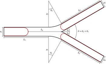
Reference Zheng, Anderson, Suresh and Grotberg2005, Reference Zheng, Fujioka, Grotberg and Grotberg2006). Here, the bifurcation is formed by the splitting of a rigid parent channel of length
 $L_{1}$
and height
 $a_{1}$
into two smaller rigid daughter channels of lengths
 $L_{2}$
and
 $L_{3}$
and heights
 $a_{2}$
and
 $a_{3}$
, respectively (see figure 1). This branching is characterized by the total branch angle
 ${\it\theta}={\it\theta}_{2}+{\it\theta}_{3}$
, where
 ${\it\theta}_{2}$
and
 ${\it\theta}_{3}$
are the branch angles for the upper and lower daughters, respectively. In the expansion region between the parent and daughter channels, the outer walls curve with a constant radius of curvature
 ${\it\rho}_{2}$
and
 ${\it\rho}_{3}$
. The carina is formed at the intersections of the daughter channels and, in our model, it is a sharp point.
We assume the plug is presplit, which is defined as the configuration when the front meniscus has already reached the carina and has split into two daughter menisci. The liquid plug is bounded by these two menisci and the rear meniscus in the parent channel. The initial size of the plug is characterized by the plug length,
 $L_{p}$
, which is the distance from the tip of the rear meniscus to the carina. The daughter channels are coated by a precursor film of height
 $h_{p}$
and the parent channel is coated by a trailing film of height
 $h_{t}$
.
The liquid plug is assumed to propagate due to a constant volumetric flow,
 $Q$
, into the rear airfinger. This constant inflow drives the liquid plug through the bifurcation, potentially splitting the plug into two daughter plugs and is chosen to mimic the experimental setup given in Zheng et al. (Reference Zheng, Anderson, Suresh and Grotberg2005).
In this paper, we will assume the bifurcation is symmetric. Therefore,
 $L_{2}=L_{3}$
,
 $a_{2}=a_{3}$
,
 ${\it\rho}_{2}={\it\rho}_{3}$
and
 ${\it\theta}_{2}={\it\theta}_{3}$
. The ratio of the height of the daughter channels with the height of the parent is assumed to be governed by the Murray–Hess law (
 $a_{2}=a_{3}=2^{-1/3}a_{1}$
).
Geometry of the two-dimensional airway bifurcation.

The bifurcation is assumed to reside in a plane within a three-dimensional gravitational field in the
 $z$
-direction (
 $\boldsymbol{g}=-\hat{\boldsymbol{k}}$
). We use a roll angle (
 ${\it\varphi}$
) and then a pitch angle (
 ${\it\psi}$
) to define the plane’s orientation within this gravitational field. The resulting gravitational field in the bifurcation plane is
 $$\begin{eqnarray}\boldsymbol{g}=g\left[\begin{array}{@{}c@{}}\sin ({\it\psi})\cos ({\it\varphi})\\ -\text{sin}({\it\varphi}),\end{array}\right]\end{eqnarray}$$
where
 $g$
is the gravitational constant. For
 ${\it\varphi}={\it\psi}=0^{\circ }$
, the bifurcation is iso-gravitational and there are no effects due to gravity. For
 ${\it\varphi}=90^{\circ }$
and
 ${\it\psi}=0^{\circ }$
, gravity is only in the
 $y$
-direction and for
 ${\it\varphi}=0^{\circ }$
and
 ${\it\psi}=90^{\circ }$
, gravity is in only the
 $x$
-direction.
Assuming that the liquid plug is a Newtonian fluid with constant material properties, the governing equations for the fluid are the dimensionless Navier–Stokes and continuity equations in two dimensions:
 $$\begin{eqnarray}\left.\begin{array}{@{}c@{}}\displaystyle La\left(\frac{\partial \boldsymbol{u}}{\partial t}+\boldsymbol{u}\boldsymbol{\cdot }\boldsymbol{{\rm\nabla}}\boldsymbol{u}\right)={\rm\nabla}^{2}\boldsymbol{u}-\boldsymbol{{\rm\nabla}}P+Bo(\sin ({\it\psi})\cos ({\it\varphi})\boldsymbol{e}_{x}-\sin ({\it\varphi})\boldsymbol{e}_{y}),\\ \displaystyle \boldsymbol{{\rm\nabla}}\boldsymbol{\cdot }\boldsymbol{u}=0,\end{array}\right\}\end{eqnarray}$$
where
 $\boldsymbol{u}=(u,v)^{\text{T}}$
is the two-dimensional fluid velocity vector,
 $P$
is the pressure,
 ${\it\psi}$
is the pitch angle,
 ${\it\varphi}$
is the roll angle,
 $\boldsymbol{e}_{x}$
and
 $\boldsymbol{e}_{y}$
are the unit vectors in the horizontal and vertical directions, respectively. The two dimensionless parameters are the Laplace number,
 $La={\it\rho}{\it\sigma}a_{1}/{\it\mu}^{2}$
, where
 ${\it\rho}$
is the fluid density,
 ${\it\sigma}$
is the surface tension on the air/liquid interface,
 ${\it\mu}$
is the fluid viscosity and the Bond number
 $Bo={\it\rho}ga_{1}^{2}/{\it\sigma}$
. Since the strength of the gravitational field within the bifurcation plane varies with the roll angle only when
 ${\it\psi}=0$
, we also define an effective Bond number,
 $Bo^{\ast }=Bo\sin ({\it\varphi})$
. We define an additional dimensionless quantity, the capillary number
 $Ca=Q{\it\mu}/a_{1}^{2}{\it\sigma}$
where
 $Q$
is the constant volumetric gas flow into the rear airfinger that drives the liquid plug.
In this paper, we assume that the gas phase is passive in parent and daughter channels. Since we are focusing on the effect of gravity on the splitting of the liquid plug, we assume that the pressures in the daughter airfingers are constant and equal. This assumes that there are no blockages or other phenomena that would cause the pressures in the daughter airfingers to vary in time. The pressure in the parent airfinger is assumed to vary as the liquid plug propagates through the bifurcation and is chosen to enforce the constant gas flow into the parent airfinger. The choice to enforce a constant gas flow rate into the parent airfinger instead of a constant pressure is done to mimic the experiments in Zheng et al. (Reference Zheng, Anderson, Suresh and Grotberg2005). In addition, we seek to examine the effect of gravity only, without inertial effects, on the splitting of the liquid plug, so we assume negligible inertia by taking
 $La\ll 1$
and assuming Stokes flow.
On the air/liquid interface, we enforce that the jump in stress depends only on surface tension effects, so
 $$\begin{eqnarray}\hat{\boldsymbol{n}}\boldsymbol{\cdot }(\boldsymbol{{\rm\nabla}}\boldsymbol{u}+\boldsymbol{{\rm\nabla}}\boldsymbol{u}^{\text{T}})-\hat{\boldsymbol{n}}P=\hat{\boldsymbol{n}}({\it\kappa}-P_{i}),\end{eqnarray}$$
where
 $\hat{\boldsymbol{n}}$
is the unit normal on the air/liquid interface,
 ${\it\kappa}$
is the curvature of the interface, and
 $P_{i}$
is the pressure in the gas phase for
 $i=1,2,3$
, which correspond to the parent, upper daughter and lower daughter airfingers, respectively. We assume the no-slip condition on the channel walls and the pressure at the inflow and both outflows is constant and equal to the pressure of the corresponding airfinger.
The motion of the air/liquid interface is captured by setting the velocity of the interface at a point equal to the velocity of the fluid at that point:
 $$\begin{eqnarray}\dot{\boldsymbol{X}}(\boldsymbol{x},t)=\boldsymbol{u}(\boldsymbol{x},t),\end{eqnarray}$$
where
 $\dot{\boldsymbol{X}}$
is the velocity of a material point on the interface.
We solve the above system of equations numerically. The computational algorithm used consists of three components: finite element solver for the Navier–Stokes and continuity equations, interface tracking using adaptive marker particles and an iterative solver for determining the pressure in the parent airfinger.
Since we are assuming
 $La\ll 1$
, we solve the quasi-steady-state Navier–Stokes and continuity equations,
 $$\begin{eqnarray}\left.\begin{array}{@{}c@{}}{\rm\nabla}^{2}\boldsymbol{u}-\boldsymbol{{\rm\nabla}}P+Bo(\sin ({\it\psi})\cos ({\it\varphi})\boldsymbol{e}_{x}-\sin ({\it\varphi})\boldsymbol{e}_{y})=0,\\ \displaystyle \boldsymbol{{\rm\nabla}}\boldsymbol{\cdot }\boldsymbol{u}=0,\end{array}\right\}\end{eqnarray}$$
for a given interface configuration using the boundary conditions discussed previously using the mixed finite element method. Here, we have used quadratic elements for the velocity and linear elements for the pressure.
The location of the interface is tracked using adaptive marker particles with cubic spline interpolation. The interface is discretized into markers that are advected passively by the fluid using the condition (2.4). The resulting system of ordinary differential equations (ODEs) are advanced in time using the forward Euler method. This method was chosen to reduce the number of solutions of the Navier–Stokes and continuity equations that more sophisticated multi-step or implicit solvers would require at the cost of the smaller timestep needed for accuracy. The time step for forward Euler update is chosen to be
 ${\rm\Delta}t=10^{-3}$
, which is sufficiently small for stability and the desired accuracy. Appendix A demonstrates the convergence and accuracy of this numerical approach. To improve the accuracy and stability of the method, the distance between marker particles is maintained within a prescribed range,
 $10^{-3}<{\rm\Delta}s<10^{-2}$
where
 ${\rm\Delta}s$
is the Eulerian distance between two adjacent markers, by adding new markers when the distance between successive particles is above the given range and the markers are removed when the distance is below the given threshold. When introducing new particles or computing interface properties such as the interface normal or curvature, cubic spline interpolation is employed to minimize numerical errors.
To enforce the given constant volumetric gas flow rate into the parent airfinger, the pressure in the parent airfinger is determined by an iterative process. We first note that the volumetric flow rate,
 $Q$
, is a function of the pressure of the parent airfinger so that
 $Q=f(P_{1})$
. We use the secant method to iteratively approximate the root of the equation
 $f(P_{1})-Q^{\ast }=0$
, where
 $Q^{\ast }$
is the prescribed volumetric flow rate using a convergence tolerance of
 ${\it\varepsilon}=10^{-3}$
. This tolerance provides sufficient accuracy in approximating the parent airfinger pressure without excessive iterations, with each timestep requiring two to three iterations per timestep. This is demonstrated in appendix B.
3 Results
Since we are interested in the effect gravity has on the splitting of a liquid plug, we examine the changes in the system as we vary the roll angle,
 ${\it\varphi}$
, and the volumetric flow of gas into the parent airfinger,
 $Q$
. The dimensionless geometric parameters are
 $a_{1}=1$
,
 $a_{2}=a_{3}=2^{-1/3}$
,
 $L_{1}=L_{2}=L_{3}=5$
,
 ${\it\theta}=60^{\circ }$
with
 ${\it\theta}_{2}={\it\theta}_{3}=30^{\circ }$
,
 $L_{p}=3.75$
unless noted. In this paper, we focus on the effect gravity has on the splitting of the liquid plug. Hence, we assume a transverse gravitational field with
 ${\it\psi}=0^{\circ }$
for all of the simulations. These parameters were chosen to match the experimental set-up in Zheng et al. (Reference Zheng, Anderson, Suresh and Grotberg2005).
We assume the trailing and precursor film thicknesses determined by the relation given by Halpern & Gaver (Reference Halpern and Gaver1994):
 $$\begin{eqnarray}h=0.417(1-\text{e}^{-1.69Ca^{0.5025}}).\end{eqnarray}$$
Here, we use the capillary numbers based on the volumetric flow rate
 $Ca=Q{\it\mu}/a_{1}^{2}{\it\sigma}$
. This choice for the trailing film thickness is made from assuming that the plug deposited fluid along the wall as it propagated through the parent channel as predicted by (3.1). The choice for the precursor thickness is arbitrary since nothing is known a priori about the thickness of the fluid lining the daughter channels, which could range from a dry wall to a fully occluded channel. While the thickness of the precursor film can cause the plug to gain or lose volume as it propagates into the daughter channel, we use the same relation for the precursor film as for the trailing film in each of the simulations since we are not studying the effect of the precursor film thickness on the splitting process in this paper.
Liquid plug position at various dimensionless times,
 $t$
, for
 ${\it\varphi}=45^{\circ }$
and
 $Ca\approx 4\times 10^{-2}$
.

The dimensionless parameters are
 $Bo=2.5$
and
 $Ca=Q\,Ca_{0}$
where
 $Ca_{0}$
is a baseline value of
 $Ca$
when
 $Q=1$
and takes the value
 $Ca_{0}\approx 0.16276$
in this paper. Note that the Bond number is different from the experiments in Zheng et al. (Reference Zheng, Anderson, Suresh and Grotberg2005) and was chosen to allow for a larger range of effective Bond numbers in the simulations.
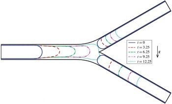
Figure 2 shows the position of the air/liquid interfaces for various dimensionless times
 $t$
where
 ${\it\varphi}=45^{\circ }$
and
 $Ca\approx 4\times 10^{-2}$
. The plug propagates from its initial configuration (
 $t=0$
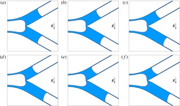
), driven by the constant gas inflow. The trailing film on the bottom wall of parent channel becomes thicker than the corresponding trailing film on the top wall of the parent channel. This is due to the buoyancy of the airfinger. Due to the gravitational field, the front meniscus in the lower daughter channel propagates at a faster rate than the meniscus in the upper daughter channel. This is due to a larger portion of the liquid plug is travelling down the gravitationally favoured daughter channel as the plug splits and will lead to an asymmetric splitting. In addition, as the rear meniscus entered the transition region where the parent channel branches into the two daughter channels, the parent airfinger expands until it reaches the carina. This is where we end the simulation and consider the plug completely split. Figure 3 shows the liquid plug of length
 $L_{p}=2$
after splitting for various roll angles,
 ${\it\varphi}$
.
Liquid plug of length
 $L_{p}=2$
after splitting for various roll angles,
 ${\it\varphi}$
: (a)
 ${\it\varphi}=0^{\circ }$
; (b)
 ${\it\varphi}=15^{\circ }$
; (c)
 ${\it\varphi}=30^{\circ }$
; (d)
 ${\it\varphi}=45^{\circ }$
; (e)
 ${\it\varphi}=60^{\circ }$
; (f)
 ${\it\varphi}=90^{\circ }$
. The liquid region is shaded in blue and air/liquid interface is denoted by the red curve. As the roll angle increases, more of the liquid plug propagates into the gravitationally favoured daughter, leading to an asymmetric splitting of the plug.

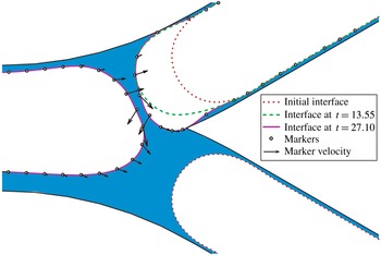
Position of the air/liquid interface over time when the top front meniscus renters the bifurcation. Since the plug is assumed to be presplit and the top front meniscus and the rear meniscus eventually will coincide, we assume the presplit plug assumption is not valid and we assume the plug would not have split, setting
 $R_{S}=0$
.

Splitting ratio,
 $R_{S}$
, versus capillary number,
 $Ca$
, for various roll angles
 ${\it\varphi}$
. The data points correspond to individual numerical simulations and the curves correspond to the curve
 $R_{S}=1-(A\,Ca)^{-p}$
, where
 $A$
and
 $p$
are determined from a nonlinear least-squares fit. The Bond number used in these simulations is
 $Bo=2.5$
.

To measure the asymmetry of the splitting, we introduce the splitting ratio,
 $R_{S}$
, which is the ratio of liquid in the upper daughter channel versus the liquid in the lower daughter channel minus the corresponding precursor film volumes. Here
 $R_{S}$
varies from 0, which corresponds to no splitting (the entire plug propagates into the gravitationally favoured daughter channel), to 1, which corresponds to a symmetric splitting (the plug splits into two equal daughter plugs). In our model, we have assumed that the plug is presplit. If it is observed that the front meniscus in the top daughter renters the bifurcation and begins to propagate into the bottom daughter channel, we assume that the presplit assumption is not valid and that the plug would not have split, setting
 $R_{S}=0$
for these simulations. Figure 4 provides an example of a simulation that demonstrates this behaviour.
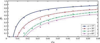
Figure 5 shows the splitting ratio versus the capillary number for various roll angles,
 ${\it\varphi}$
, with
 $Bo=2.5$
.
 $R_{S}$
increases as the capillary number increases and
 $R_{S}\rightarrow 1$
as
 $Ca\rightarrow \infty$
so the splitting becomes more symmetric as the plug speed increases. This occurs because the pressure difference due to gravity becomes less significant as the overall pressure drop increases, which leads to a more symmetric splitting. As the roll angle,
 ${\it\varphi}$
, increases,
 $R_{S}$
decreases with
 $R_{S}\equiv 1$
for all
 $Ca>0$
when
 ${\it\varphi}=0^{\circ }$
(not shown), which corresponds to the bifurcation being iso-gravitational and, hence, each the plug will always split symmetrically. In addition, there exists a critical capillary number,
 $Ca_{\mathit{crit}}$
, such that for
 $Ca\leqslant Ca_{\mathit{crit}}$
,
 $R_{S}=0$
and the plug does not split into two daughter plugs but propagates completely into the lower daughter channel. This is due to the existence of a minimal driving pressure, which corresponds to a minimal
 $Ca$
, that is required to overcome gravity before any fluid can go uphill. Below this minimal driving pressure, no fluid goes uphill and the plug does not split. Note that this critical capillary number decreases as the roll angle decreases and becomes
 $Ca_{c}=0$
when
 ${\it\varphi}=0^{\circ }$
. In addition, figure 5 shows the nonlinear least-squares fit using the results from numerical simulations for discrete values of
 $Ca$
and
 ${\it\varphi}$
. We use a fit of the form
 $$\begin{eqnarray}R_{S}(Ca,{\it\varphi})=1-A({\it\varphi})\,Ca^{-p({\it\varphi})},\end{eqnarray}$$
where
 $A$
and
 $p$
are parameters that depend on the roll angle,
 ${\it\varphi}$
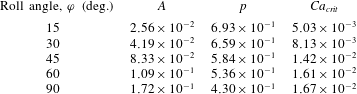
, and are given in table 1. The parameters
 $A$
and
 $p$
appear to vary linearly with the roll angle so we now assume
 $A=a{\it\varphi}$
and
 $p=b-c{\it\varphi}$
and determine the parameters
 $a$
,
 $b$
, and
 $c$
by minimizing the sum of the errors for
 $A$
,
 $p$
, and
 $Ca_{\mathit{crit}}$
using the constraint that
 $Ca_{\mathit{crit}}$
must be a monotonically increasing function of
 ${\it\varphi}$
. This fitting produces the values
 $a=1.846\times 10^{-3}$
,
 $b=0.753$
, and
 $c=3.59\times 10^{-3}$
. From this, the splitting ratio can be written as
 $$\begin{eqnarray}R_{S}(Ca,{\it\varphi})=1-(a{\it\varphi})Ca^{-(b-c{\it\varphi})},\end{eqnarray}$$
with the critical capillary number given by
 $$\begin{eqnarray}Ca_{\mathit{crit}}=(a{\it\varphi})^{(b-c{\it\varphi})^{-1}}.\end{eqnarray}$$
Parameter values obtained from nonlinear least-square fits of the numerical results to (3.2) for various roll angles. The Bond number used to obtain these results is
 $Bo=2.5$
.

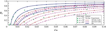
To assess the accuracy of our model, we compare the results from the two-dimensional model with the experimental and one-dimensional results from the LB-400-X dataset in Zheng et al. (Reference Zheng, Anderson, Suresh and Grotberg2005) and the one-dimensional model from Filoche et al. (Reference Filoche, Tai and Grotberg2015). Note that the experimental and theoretical results from Zheng et al. (Reference Zheng, Anderson, Suresh and Grotberg2005) are for dry walls in the daughters and the two-dimensional model presented here and the one-dimensional model in Filoche et al. (Reference Filoche, Tai and Grotberg2015) have wet walls in the daughters. Since the Bond number used to generate the results presented in figure 5 and table 1, and the nonlinear fitting is
 $Bo=2.5$
and the Bond number used in the dataset from Zheng et al. (Reference Zheng, Anderson, Suresh and Grotberg2005) is
 $Bo=1.26$
, we must adjust the roll angle before we can compare results.
The gravity term in the
 $y$
-direction in the Navier–Stokes equation (2.2) is
 $Bo\sin ({\it\varphi})$
. Since there are two degrees of freedom in this term, we are able to compare the data generated using two different value of
 $Bo$
by varying
 ${\it\varphi}$
under certain conditions. To do this, we define the effective Bond number
 $Bo^{\ast }=Bo\sin ({\it\varphi})$
and let
 $Bo_{2D}=2.5$
denote the Bond number used to generate the two-dimensional data and
 $Bo_{Z}=1.26$
the Bond number used in Zheng et al. (Reference Zheng, Anderson, Suresh and Grotberg2005). We can compute the appropriate roll angle that equates the gravity terms using the relation
 $$\begin{eqnarray}{\it\varphi}_{2D}=\sin ^{-1}\left(\frac{Bo_{Z}}{Bo_{2D}}\sin ({\it\varphi}_{Z})\right),\end{eqnarray}$$
where
 ${\it\varphi}_{2D}$
is the roll angle to use with (3.3) to compare with the roll angle
 ${\it\varphi}_{Z}$
data from Zheng et al. (Reference Zheng, Anderson, Suresh and Grotberg2005). This is valid if
 $Bo_{\text{Z}}\sin ({\it\varphi})\leqslant Bo_{2D}$
. Using this conversion, we compare the three models with the experimental data in figure 6 and observe improved agreement between the two-dimensional model and the experimental results compared with the one-dimensional models for capillary numbers close to the critical value. This allows for improved prediction of when the plug will or will not split.
When we compare the two one-dimensional models, we see the presence of a contact line in the dry wall model causes an increase in the splitting ratio compared with the wet wall model. This suggests that the two-dimensional model would underpredict the splitting ratio compared with a two-dimensional model that included the contact lines, which is not presented here.
Each theoretical model overpredicts the splitting ratio compared with the experiments for larger
 $Ca$
with the two-dimensional model having a larger overprediction compared with the one-dimensional models. This suggests that neglecting inertial effects and the presplit plug assumption might not yield a good approximation for this range of capillary numbers since this assumption assumes that the front meniscus has split symmetrically and neglects the asymmetrical shape of the menisci before it reaches the bifurcation that can occur due to gravity. This might cause an increased predicted splitting ratio, which corresponds to a more symmetric splitting that was is expected.
Comparison of the splitting ratio,
 $R_{S}$
, between the two-dimensional model and the one-dimensional and benchtop models in Zheng et al. (Reference Zheng, Anderson, Suresh and Grotberg2005) and the one-dimensional model in Filoche et al. (Reference Filoche, Tai and Grotberg2015). For each line, the markers indicate which roll angle was used. The Bond number used in this figure is
 $Bo=1.26$
and corresponds to the LB-400-X fluid in Zheng et al. (Reference Zheng, Anderson, Suresh and Grotberg2005).

In addition to measuring the splitting ratio, we examined the stresses exerted by the propagation of the liquid plug on the airway walls and the effect the presence of a bifurcation has on these stresses. The presence of an air/liquid interface can induce large stresses and stress gradients on the airway walls and can potentially damage pulmonary epithelial cells. The parameters in the results below are
 $Ca\approx 4\times 10^{-2}$
and
 ${\it\varphi}=45^{\circ }$
.
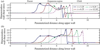
Figure 7 shows the dimensionless wall shear stress,
 ${\it\tau}_{s}$
, along the top and bottom walls of the entire bifurcation at various dimensionless times,
 $t$
. There is in increase in
 ${\it\tau}_{s}$
near the rear meniscus and a large spike near the front menisci. The spikes in
 ${\it\tau}_{s}$
propagate with the menisci and we see a decrease
 ${\it\tau}_{s}$
near the rear meniscus when it enters the expansion region of the bifurcation. This is due to a decrease in the propagation speed of the meniscus when it begins to expand in this region due to conservation of mass.
Dimensionless wall shear stress on the upper and lower bifurcation walls at various dimensionless times,
 $t$
. The region between the vertical dotted lines corresponds to the expansion region in the bifurcation. The triangles mark the location of the tip of the front menisci and the circles mark the location of the tip of the rear meniscus.

In figure 8, the values of
 ${\it\tau}_{s}$
at dimensionless time
 $t=3.25$
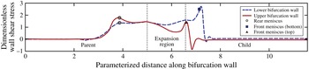
are shown for both the upper and lower walls of the entire bifurcation. We can observe both the increase in
 ${\it\tau}_{s}$
near the rear meniscus with the upper bifurcation wall taking a larger value. This is from the thinning of the trailing film due to gravity. As the trailing film thins,
 ${\it\tau}_{s}$
increases and we observe an asymmetry due to gravity. There is a distinct asymmetry in the spikes in
 ${\it\tau}_{s}$
near the front menisci, with the lower bifurcation wall taking a much larger value than the upper bifurcation wall. This is due to the increased speed of the lower front meniscus when compared with the upper front meniscus. Note that the
 ${\it\tau}_{s}$
is higher near the rear meniscus than near the front meniscus on the upper bifurcation wall.
Dimensionless wall shear stresses on the upper and lower bifurcation walls at
 $t=3.25$
. The region between the vertical dotted lines corresponds to the expansion region in the bifurcation. The square and triangle mark the location of the tip of the front meniscus in the top and bottom daughters, respectively, and the circles mark the location of the tip of the rear meniscus.

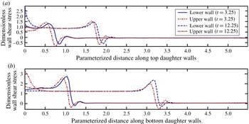
Figure 9 shows
 ${\it\tau}_{s}$
on the walls of the upper and lower daughter channels at
 $t=3.25$
and
 $t=12.25$
, which corresponds to the time when the rear meniscus reached the carina. The walls of the lower daughter channel see a higher
 ${\it\tau}_{s}$
than the walls of the upper daughter channel. In addition, the highest
 ${\it\tau}_{s}$
occurs at the carina, which is expected due to the sharp point at the carina.
Dimensionless shear stresses on the walls of the top and bottom daughter channels for
 $t=3.25$
and
 $t=12.25$
. The point
 $x=0$
corresponds to the carina in the upper (lower) wall of the bottom (top) daughter channel and the point closest to the carina on the opposite walls.

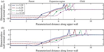
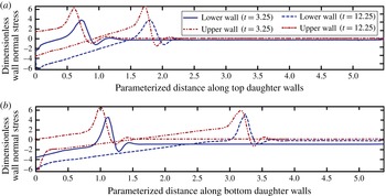
Dimensionless wall normal stress on the upper (
 ${{\it\tau}_{n}}_{\mathit{upper}}$
) and lower (
 ${{\it\tau}_{n}}_{\mathit{lower}}$
) bifurcation walls for various dimensionless times,
 $t$
. The region between the vertical dotted lines corresponds to the expansion region in the bifurcation. The triangles mark the location of the tip of the front menisci and the circles mark the location of the tip of the rear meniscus. Note that in this figure, we have plotted
 $-{{\it\tau}_{n}}_{\mathit{upper}}$
for comparison purposes.

In addition to the wall shear stress, we computed the wall normal stresses,
 ${\it\tau}_{n}$
, on the walls of the bifurcation. Figure 10 shows
 ${\it\tau}_{n}$
on the lower bifurcation wall for various dimensionless times. The value of
 ${\it\tau}_{n}$
is approximately constant in the trailing and precursor films with a linear increase from the tip of the rear meniscus to the tip of the lower front meniscus. Since
 ${\it\tau}_{n}$
is essentially the negative of the pressure, we observe an approximately linear drop in pressure within the liquid plug. Near the front meniscus, we see a large spike in
 ${\it\tau}_{n}$
, which decreases when the rear meniscus propagates through the expansion region. This is due to the drop in driving pressure as the tip of the parent airfinger expands.
Dimensionless wall normal stresses on the upper (
 ${{\it\tau}_{n}}_{\mathit{upper}}$
) and lower (
 ${{\it\tau}_{n}}_{\mathit{lower}}$
) bifurcation walls at
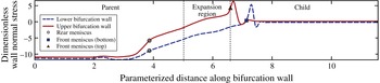
 $t=3.25$
. The region between the vertical dotted lines corresponds to the expansion region in the bifurcation. The square and triangle mark the location of the tip of the front meniscus in the top and bottom daughters, respectively, and the circles mark the location of the tip of the rear meniscus. Note that in this figure, we have plotted
 $-{{\it\tau}_{n}}_{\mathit{upper}}$
, for comparison purposes.

Dimensionless normal stress on the upper (
 ${{\it\tau}_{n}}_{\mathit{upper}}$
) and lower (
 ${{\it\tau}_{n}}_{\mathit{lower}}$
) walls of both the top and bottom daughter channels for
 $t=3.25$
and
 $t=12.25$
. The point
 $x=0$
corresponds to the carina in the upper (lower) wall of the bottom (top) daughter channel and the point closest to the carina on the opposite wall. Note that in this figure, we have plotted
 $-{{\it\tau}_{n}}_{\mathit{upper}}$
for comparison purposes.

Figure 11 shows
 ${\it\tau}_{n}$
on the upper and lower bifurcation walls at
 $t=3.25$
. There is a slight difference in
 ${\it\tau}_{n}$
in the trailing and precursor films due to the hydrostatic pressure gradient. The hydrostatic pressure gradient is more pronounced within the liquid plug and the peak in
 ${\it\tau}_{n}$
is higher on the upper bifurcation wall than on the lower. This is due to the slower propagation speed of the upper front meniscus. Figure 12 shows
 ${\it\tau}_{n}$
on the walls of both daughter channels. There is a decrease in
 ${\it\tau}_{n}$
on the bottom walls of both the top and bottom daughter channels, with the effect slightly more pronounced in the top daughter (from slightly above six to slightly above four in the bottom daughter while it drops to less than four in the top daughter). Once again, the highest value of
 $|{\it\tau}_{n}|$
is observed near the carina.
4 Conclusion
In this paper, we introduced a two-dimensional pulmonary bifurcation model to study the behaviour of a presplit liquid plug driven by a constant gas inflow and subject to a transverse gravitational field. We observed that the presence of a transverse gravitational field induces asymmetries in plug splitting, which are mitigated by an increase in the driving gas flow rate. This is in agreement with previous experimental and analytical models introduced by Zheng et al. (Reference Zheng, Anderson, Suresh and Grotberg2005) and Filoche et al. (Reference Filoche, Tai and Grotberg2015). We measured the asymmetry of the splitting using the splitting ratio,
 $R_{S}$
, and generated sufficient numerical data to allow for a nonlinear least-squares fit to that could be used to predict an approximate splitting ratio for a given roll angle and capillary number.
Since the presence of an air/liquid interface can induce large wall stresses and stress gradients, which can potentially damage or kill pulmonary epithelial cells, we computed the wall stresses to observe the effect of the bifurcation geometry and the transverse gravitational field. The highest stresses are observed near the carina. In addition, the stress distribution on the bifurcation walls is asymmetric in the presence of a transverse gravitational field. The largest wall shear stress occurs on the lower daughter channel walls due to the increased propagation speed of the front meniscus. The largest wall normal stress occurs on the upper daughter channel walls.
This work is an additional step towards the development of tools and observations to develop an improved model capable of predicting the distribution of instilled liquids in the lungs and allows for targeted delivery by manipulation of instillation rate, gravitational orientation, material properties of the instilled liquid and instillation volume. Models such as that presented here as well as improved models that include the effects of other phenomena such as inertia and the presence of soluble and insoluble surfactants coupled with organ-level models such as that presented in Filoche et al. (Reference Filoche, Tai and Grotberg2015) could become a highly accurate tool for understanding the dynamics of instilled liquids in the lungs.
Acknowledgements
Research reported in this publication was supported by the National Institutes of Health under Award numbers HL84370 and HL85156.
Appendix A. Convergence results for the numerical method
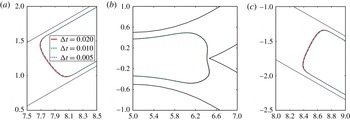
To demonstrate the convergence of the numerical methods described in § 2, we ran three simulations with different
 ${\rm\Delta}t$
values using
 $Ca=8.14\times 10^{-2}$
. As shown in figure 13, the position of the air/liquid interface approaches a unique solution, indicating the described numerical method is convergent with the estimated error for
 ${\rm\Delta}t=10^{-2}$
being approximately
 $E\approx 1.54\times 10^{-5}$
. Since the velocity of the interface increases with increasing
 $Ca$
and the value of
 $Ca$
chosen is at the upper end of the range studied, the choice of
 ${\rm\Delta}t=10^{-3}$
will provide sufficient accuracy.
Position of the two front menisci and the rear meniscus as the rear meniscus approaches the carina for different
 ${\rm\Delta}t$
values: (a) top daughter; (b) parent; (c) bottom daughter. The position of the air/liquid interfaces converges as
 ${\rm\Delta}t$
is reduced with
 ${\rm\Delta}t=10^{-2}$
and
 ${\rm\Delta}t=5\times 10^{3}$
having a maximum difference of
 $E\approx 1.54\times 10^{-5}$
. The capillary number for these simulations is
 $Ca=8.14\times 10^{-2}$
, which is at the upper end of the range of
 $Ca$
studied, indicating that
 ${\rm\Delta}t=10^{-3}$
is sufficiently small to provide the desired accuracy needed for this study.

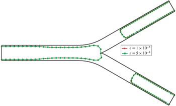
Position of the air/liquid interfaces as the rear meniscus approaches the carina for different values of the convergence tolerance in the pressure iteration. It is observed that reducing the tolerance below
 ${\it\varepsilon}=10^{-3}$
does not provide an appreciable increase in accuracy of the interface position. The capillary number in these simulations was
 $Ca=8.14\times 10^{-2}$
.

Appendix B. Convergence results of the pressure iteration
To demonstrate the convergence of the iterative method used to determine the pressure in the parent airfinger, the convergence tolerance was reduced from
 ${\it\varepsilon}=10^{-3}$
to
 ${\it\varepsilon}=5\times 10^{-4}$
. Figure 14 shows the position of the marker particles and the interpolated air/liquid interfaces for both simulations as the rear meniscus approaches the carina. There is no appreciable difference between the two solutions, which suggests that the choice of convergence tolerance,
 ${\it\varepsilon}=10^{-3}$
, used in this study is sufficient to provide a sufficiently accurate approximation of the solution. In both of these simulations,
 $Ca=8.14\times 10^{-2}$
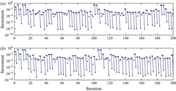
. Figure 15 shows the increment between successive pressure iterations. We observe rapid convergence in normally two or three iterations when
 ${\it\varepsilon}=10^{-3}$
while a slight increase in the number of iterations needed for convergence when
 ${\it\varepsilon}=5\times 10^{-3}$
.
Values of the increment for successive pressure iterations for convergence tolerances (a)
 ${\it\varepsilon}=10^{-3}$
and (b)
 ${\it\varepsilon}=5\times 10^{-4}$
. Each circle represents a pressure iteration with the connecting lines indicating a single timestep. We observe rapid convergence normally after two or three iterations for both
 ${\it\varepsilon}=10^{-3}$
and
 ${\it\varepsilon}=5\times 10^{-4}$
. The capillary number in these simulations was
 $Ca=8.14\times 10^{-2}$
.