Soft machines and soft active materials
Machines in engineering use mostly hard materials, while machines in nature are often soft. This conspicuous contrast has been an inspiration for the nascent field of soft machines. What does softness impart to the life of animals and plants? Softness enables deformation, which in turn provides vital functions. Familiar examples include the beating of a heart, sound shaped by the vocal folds, sound heard by the ear, movements in the gastrointestinal tract, and adjustment of the focal length of the eye.Reference Guyton and Hall1
A camera is often said to mimic the eye, but it is the differences between the two—rather than their similarities—that intrigue and inspire. The camera adjusts its focal length by zooming, while the eye does so by deforming the lens. Zooming—a rigid-body translation—requires large space and is unsuitable for slim mobile phones. The worldwide adoption of mobile phones has motivated the development of deformable lenses; for example, an elastomeric lens can change its curvature by deforming in response to an applied voltage.Reference Carpi, Frediani, Turco and De Rossi2
In plants, the rate of flow of water changes in response to variations in the concentration of salt. This regulation is thought to be mediated by pectins, polysaccharides that are present in jellies and jams.Reference Zwieniecki, Melcher and Holbrook3 Pectins imbibe water and swell, forming hydrogels. The amount of swelling changes in response to the variation in the concentration of salt. The swelling alters the size of the microchannels in the plants, regulating the rate of flow. The swelling of gels is being exploited in engineering to regulate microfluidics,Reference Beebe, Moore, Bauer, Yu, Liu, Devadoss and Jo4 seal oil wells,Reference Cai, Lou, Ganguly, Robisson and Suo5 and modulate light.Reference Sidorenko, Krupenkin, Taylor, Fratzl and Aizenberg6 Many applications of hydrogels involve the interaction between mechanics and chemistry. Such an interaction is illustrated by hydrogels in superabsorbent diapers: babies feel dry when sitting on wet diapers.Reference Masuda7
Figure 1 presents a schematic of these examples and the flow from stimulus to function. The environment provides stimuli, the stimuli cause materials to deform, and deformation gives rise to functions. Materials capable of large deformation connect the stimuli to functionality. We call such a material a soft active material (SAM). The material is soft in order to undergo large and reversible deformation and is active in order to respond to stimuli in addition to mechanical forces. Soft active materials in engineering are apt in mimicking a salient feature of life: movements in response to stimuli. An electric field can cause an elastomer to stretch several times its length. A change in pH can cause a hydrogel to swell many times its volume. A soft active material is a transducer, converting energy from one form to another.
The environment provides stimuli such as the application of a force (F), a change in pH, and a change in temperature (T). In response to the stimuli, a soft active material (SAM) deforms. The deformation provides functions such as a change in focal length and a change in flow rate.

This article describes the mechanics inspired by the emerging field of soft machines. We begin with hybrids of soft and hard materials, where mechanics meets geometry to enable large deformation of a structure, while keeping the components of hard materials intact. We then describe two examples of soft active materials: dielectric elastomers and hydrogels, where mechanics meets electrostatics and chemistry to create soft transducers. The emphasis of this article is on mechanics. Mechanics enables many designs of stretchable electronics that integrate hard materials and soft materials. Many more examples of stretchable electronics and soft materials are described in other articles in this issue of MRS Bulletin.
Islands of stiff materials on polymer substrates
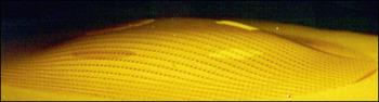
Enthusiasm for creating soft machines notwithstanding, few soft machines can be made entirely of soft materials. Rather, soft machines will be mostly hybrids of soft and hard materials. For example, one may wish to use silicon as a semiconductor, indium oxide as a transparent conductor, or silicon nitride as a hermetical seal. One way to use the hard materials in deformable devices is to fabricate islands of the hard materials on a substrate made of a polymer (Figure 2).Reference Hsu, Bhattacharya, Gleskova, Huang, Xi, Suo, Wagner and Sturm8 This basic design highlights many issues concerning mechanics.Reference Suo, Vlassak and Wagner9
Islands of stiff materials are fabricated on a flat foil of polyimide. The foil is then clamped by a circular ring of 6 cm in diameter and is deformed plastically by pressured gas into a spherical cap.Reference Hsu, Bhattacharya, Gleskova, Huang, Xi, Suo, Wagner and Sturm8

A thin, flat substrate can be bent into a cylindrical shape with a small radius. According to the elementary theory of beams, when a substrate of thickness H is bent to a radius of curvature r, the strain on the surface of the substrate is ε = H/(2r). For example, ε = 0.5% for H = 0.1 mm and r = 10 mm. This estimate of strain can be made more accurate by considering effects such as variations in elastic moduli between the substrate and the islands, and the residual stresses in the islands, but the conclusion remains true that strains in flexible electronics can be made quite small. Furthermore, when a thin sheet is bent down, the top surface is in tension, and the bottom surface is in compression. The middle surface, however, is not under any strain and is called the neutral surface. To reduce strains in hard materials, one may place them on the neutral surface by laminating the substrate with another layer of material.Reference Suo, Ma, Gleskova and Wagner10
Deformation of a flat substrate to a non-developable surface—such as spherical surface—is more difficult than to a cylindrical one.Reference Hsu, Bhattacharya, Gleskova, Huang, Xi, Suo, Wagner and Sturm8, Reference Ko, Stoykovich, Song, Malyarchuk, Choi, Yu, Geddes, Xiao, Wang, Huang and Rogers11 Transforming a flat surface to a non-developable surface requires that the substrate be stretched, and the strain cannot be reduced by thinning the substrate. Stretching a substrate while keeping the islands of hard materials intact is difficult and requires several considerations.
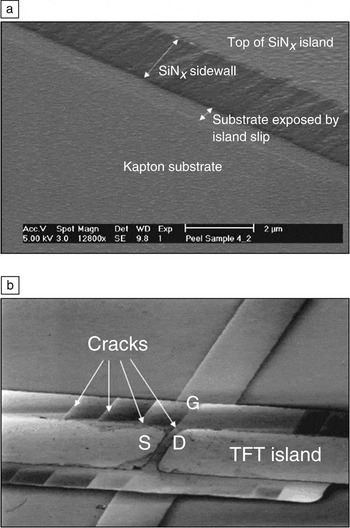
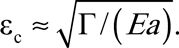
When a polymer substrate is stretched beyond a critical strain, the islands may debond from the substrate, or form cracks (Figure 3). The islands are thin films, and flaws in the islands are also small, such that the islands can sustain higher strains than their bulk counterparts. According to fracture mechanics, for an island made of a brittle material, the critical strain to cause fracture is approximately
For islands of stiff materials fabricated on a polymeric substrate, when the substrate is stretched, damage may occur by (a) debondingReference Bhattacharya, Salomon and Wagner12 or (b) cracking.Reference Gleskova, Wagner and Suo13 Note: S, source; D, drain; G, gate; TFT, thin-film transistor. The distance between the source and drain is 15 μm (b).

Here the fracture energy Γ and Young’s modulus E are material properties independent of the feature size; the flaw size a is typically on the order of the film thickness. Considering representative values, Γ = 10 J/m2, E = 1011 N/m2, and a = 10−6 m, we estimate that the critical strain is εc = 1%. More detailed calculations show that the critical strain applied on a substrate increases when the substrate has a low elastic modulus and the islands are small.Reference Lu, Yoon and Suo14 For example, islands of silicon nitride on a substrate of a polyimide crack and debond when the substrate is stretched by only a few percent.Reference Gleskova, Wagner and Suo13 In contrast, islands of diamond-like carbon on a substrate of an elastomer (PDMS) remain intact even when the substrate is stretched beyond 25%.Reference Lacour, Wagner, Narayan, Li and Suo15
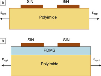
The islands of stiff materials can be isolated from the strains imposed on the substrate by a thin layer of a soft material.Reference Kim, Kim, Wu, Liu, Song, Kim, Huang, Hwang and Rogers16, Reference Sun, Lu, Yoon, Oh, Suo and Vlassak17Figure 4 illustrates two types of specimens: one with islands of silicon nitride on a substrate of polyimide, and the other with islands of silicon nitride on a substrate of polyimide coated with a thin layer of PDMS.Reference Sun, Lu, Yoon, Oh, Suo and Vlassak17 Experiments show that islands on bare polyimide crack when the substrate is pulled at small strains, ∼1%. By contrast, samples with the PDMS interlayer can be stretched to strains over 20%. This strain-isolation effect has been quantified by using a shear-lag model, in which the shear stress in the PDMS interlayer couples the islands and the substrate.Reference Sun, Lu, Yoon, Oh, Suo and Vlassak17 The strain-isolation interlayer decouples the choices of electronic materials and substrates. High-performance electronics can be made on fabric, vinyl, leather, and paper.Reference Kim, Kim, Wu, Liu, Song, Kim, Huang, Hwang and Rogers16
(a) SiN islands are fabricated on a polyimide substrate. (b) The polyimide substrate is first coated with a thin layer of polydimethylsiloxane (PDMS), and SiN islands are fabricated on PDMS. The soft PDMS interlayer isolates the SiN islands from the strain applied (εappl) to the polyimide substrate. Adapted from Reference Reference Sun, Lu, Yoon, Oh, Suo and Vlassak17.

Wrinkling, twisting, and necking
Helical springs can elongate substantially, even though materials that make the springs—metals and plastics—can only recover from small strains. One could fabricate electronic circuits on a helical platform, but this approach would require microfabrication in three dimensions, a technology that requires substantial development itself. To be compatible with planar microfabrication technology, the platform must be planar.
Several designs of stretchable electronics use planar microfabrication technology and achieve stretchability through wrinkles and twists. It has been shown that wavy metal interconnects on elastomeric substrates can sustain more than 200 cycles of loading and unloading with a strain amplitude of 25%.Reference Gray, Tien and Chen18 It has also been shown that a metal film with initial microcracks can sustain large elongation of the substrate.Reference Lacour, Wagner, Huang and Suo19 Stretchable electronics have been fabricated with single-crystal silicon in wrinkled shapes.Reference Khang, Jiang, Huang and Rogers20
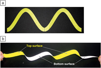
Figure 5 shows a serpentine strip cut from a piece of paper. When the strip is pulled, it twists out of the plane.Reference Li, Suo, Lacour and Wagner21 The serpentine strip is initially flat and, on pulling, acts like a helical spring: the strip elongates substantially but keeps the strain small. The same principle applies to a thin film of a stiff material suitably patterned and bonded to a compliant substrate. A large elongation of the substrate induces small strains in the film, and the film accommodates the large elongation by twisting out of the plane. Such a patterned film can serve as a platform on which entire electronic circuits can be fabricated using the planar microfabrication technology. These circuits will function without appreciable fatigue when the substrate is repeatedly bent, twisted, and stretched. Furthermore, the out-of-plane twisting of the patterned platform requires only the compliance of the top layer of the substrate. Underneath such a compliant top layer, a less compliant material may be used as a backing if some overall rigidity is desired.Reference Li, Suo, Lacour and Wagner21
(a) A serpentine strip is cut out of a piece of paper. (b) When the strip is pulled, it elongates by twisting out of plane.Reference Li, Suo, Lacour and Wagner21

We next turn to the stretchability of thin metal films. Compared to bulk metals, freestanding thin metal films yield at high stresses but rupture at small strains. For example, when single-crystal gold films, 50–200 nm thick, are stretched in a transmission electron microscope, the films deform elastically to about 1% strain and rupture.Reference Li, Huang, Xi, Lacour, Wagner and Suo22 This behavior can be understood in terms of dislocations. Upon initiation, dislocations move across the film and escape from the surfaces. The film strains plastically but does not harden. Subsequent thinning localizes in a segment of the film, of a length comparable to the thickness of the film, leading to rupture. The total length of the film is much larger than its thickness, such that the overall strain at rupture is slightly beyond the elastic limit.
While the local elongation is accommodated in the freestanding metal film by the ruptured halves moving apart, local elongation cannot be so accommodated for a metal film bonded to a substrate of a relatively stiff polymer, such as polyimide. This constraint from the substrate delocalizes strain in the film so that the film deforms uniformly to a large strain. Indeed, for such a metal film on a polymer substrate to rupture by localized deformation, the localized deformation must be accommodated by debonding of the interface over a length larger than the thickness of the film.Reference Li, Huang, Xi, Lacour, Wagner and Suo22
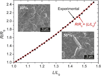
Large strains in metal films adherent to polymer substrates have been demonstrated experimentally.Reference Lu, Wang, Suo and Vlassak23 When a copper film is adherent to a polyimide substrate, the sample can be strained beyond 50% without rupturing the copper film. Furthermore, the electrical resistance of the metal film increases with elongation in a way predicted based on the assumption that the film retains its rectangular shape during deformation, and the resistivity of the film remains unchanged during the deformation. These assumptions lead to the prediction R/R 0 = (L/L 0)2, where R and L are the electrical resistance and the length of the stretched film, respectively, and R 0 and L 0 are the resistance and length of the unstrained film, respectively. In the full range of deformation, negligible deviation is found between the measured resistance and the theoretical prediction (Figure 6). Images taken in a scanning electron microscope show no cracks in a film strained 40%, and only a few isolated short cracks at 50%. This experiment was terminated when the substrate ruptured at an elongation of 56%.Reference Lu, Wang, Suo and Vlassak23
A 1-μm-thick Cu film is deposited on a polyimide substrate, with a 10-nm-thick Cr interlayer to improve adhesion. The sample is annealed and then subjected to a tensile load. The electrical resistance R increases with the length L of the specimen, both quantities being normalized by the initial values, R 0 and L 0, respectively. The squares are experimental data, and the curve is the theoretical prediction. Microcracks are observed at an elongation of 50%, but not at an elongation of 40%.Reference Lu, Wang, Suo and Vlassak23

Dielectric elastomers
Recently a soft robot has been made exclusively with an elastomer.Reference Shepherd, Ilievski, Choi, Morin, Stokes, Mazzeo, Chen, Wang and Whitesides24 The robot is capable of sophisticated locomotion and is actuated by pumping air through a network of channels. While this and many other soft machines have been demonstrated with familiar materials, intense efforts are being made to develop new actuation materials. It was discovered a decade ago that voltage can cause a dielectric elastomer to strain beyond 100%.Reference Pelrine, Kornbluh, Pei and Joseph25 This discovery has inspired the creation of muscle-like transducers. In addition to large voltage-induced strains, attributes of dielectric elastomers include fast response, lightweight, silent operation, ease of processing, and low cost. Promising applications range from adaptive optics to energy harvesting.Reference Carpi, De Rossi, Kornbluh, Pelrine and Sommer-Larsen26–Reference Carpi, Bauer and De Rossi28 The mechanics of coupled large deformation and electrostatics dates back to the 1950sReference Toupin29 and has since gained momentum.Reference Goulbourne, Mockensturm and Frecker30–Reference Suo33
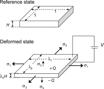
Figure 7 illustrates the principle of operation of a dielectric elastomer transducer. A membrane of a dielectric elastomer is sandwiched between two electrodes. When the transducer is subjected to a voltage, charge flows through a conducting wire from one electrode to the other. The charges of opposite sign on the two electrodes cause the membrane thickness to reduce and the area to be enlarged. For the elastomer to deform substantially, the electrodes are even softer than the elastomer. A commonly used substance for electrodes in dielectric elastomer transducers is carbon grease—a mixture of a fluid and carbon particles. Other options include carbon nanotubes, silver nanowires, and salt water. Charge can also be sprayed, by using a corona, onto the surface of the elastomer without electrodes.Reference Keplinger, Kaltenbrunner, Arnold and Bauer34
A dielectric elastomer in the reference state and in a deformed state. In the reference state, the membrane is of unit area and of thickness H. Note: σ1, σ2, σ3, applied stresses in the 1, 2, and 3 directions, respectively; λ1, λ2, λ3, stretches in the 1, 2, and 3 directions, respectively; Q, charge; and V, applied voltage.

An elastomer is a three-dimensional network of long and flexible polymers held together by cross-links. Each polymer chain consists of a large number of monomers. Consequently, the cross-links have a negligible effect on the polarization of the monomers—that is, the elastomer can polarize nearly as freely as a polymer melt. This molecular picture is consistent with the following experimental observation: the permittivity changes by only a few percent when a membrane of an elastomer is stretched to increase the area 25 times.Reference Kofod, Sommer-Larsen, Kornbluh and Pelrine35 As an idealization, known as the model of ideal dielectric elastomers,Reference Zhao, Hong and Suo36 the dielectric behavior of an elastomer is assumed to be liquid-like. That is, the electric displacement relates to the electric field E el as D = εelE el, where ε is the permittivity of the elastomer, taken to be a constant independent of deformation.
With reference to Figure 8, if σ1, σ2, and σ3 are the stresses applied to the membrane, λ1, λ2, and λ3 are the stretches, and the elastomer is considered to be incompressible, λ1 λ2 λ3 = 1. Then the model for an ideal dielectric elastomer takes the form


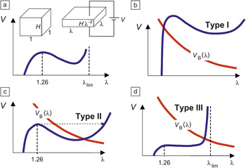
Three types of behavior of a dielectric transducer.Reference Zhao and Suo42 The blue curves are the equation of state V(λ). The red curves are the breakdown voltage as a function of stretch, V B(λ). (a) A membrane of a dielectric elastomer subject to a voltage reduces thickness and expands area. The voltage-stretch curve is typically not monotonic, reaching local maximum at a stretch of 1.26. (b–d) Three types of behavior are distinguished, depending on where the two curves, V(λ) and V B(λ), intersect. Note: H, thickness; λ, stretch; λlim, limiting stretch; V, applied voltage; V B(λ), breakdown voltage.

where W stretch (λ1, λ2) is the Helmholtz free energy associated with stretching the elastomer without the presence of an electric field. The two equations are readily interpreted: the elasticity of the network—the right-hand side of Equations 2 and 3—are balanced by the applied stresses and by the Maxwell stress εelE el2.Reference Pelrine, Kornbluh, Pei and Joseph25 This model has been reviewed, along with models of nonideal dielectric elastomers.Reference Suo33 The stress-stretch relations can be determined by experimental measurements.Reference Lochmatter, Kovacs and Michel37
While all dielectrics deform under voltage, the amount of deformation differs markedly among different materials. Under a voltage, piezoelectric ceramics attain strains of typically less than 1%. Glassy and semi-crystalline polymers can attain strains of less than 10%.Reference Zhang, Bharti and Zhao38 Strains over 100% have been achieved for soft materials in several ways, such as by pre-stretching an elastomer,Reference Suo33 by using an elastomer of interpenetrating networks,Reference Ha, Yuan, Pei, Pelrine and Stanford39 and by swelling an elastomer with a solvent.Reference Shankar, Ghosh and Spontak40
These experimental advances have prompted a theoretical question: What is the fundamental limit of deformation that can be induced by voltage? After all, one can easily increase the length of a rubberband several times by using a mechanical force. Why is it difficult to induce large strain by applying a voltage?
The difficulty in inducing large deformation by voltage has to do with two modes of failure: electrical breakdown and electromechanical instability. For a stiff dielectric such as a ceramic or a glassy polymer, voltage-induced deformation is limited by electrical breakdown, when the voltage mobilizes charged species in the dielectric to produce a path of electrical conduction. For a compliant dielectric such as an elastomer, the voltage-induced deformation is often limited by electromechanical instability, or pull-in instability, caused by the positive feedback between the reduction in thickness and increase in electric field.
The pull-in instability has long been recognized as a mode of failure of soft dielectrics.Reference Stark and Garton41 It has been shown recently, however, that the pull-in instability can be harnessed to enable giant voltage-induced deformation.Reference Zhao and Suo42 As illustrated in Figure 8a, subject to voltage V, the membrane stretches by a factor of λ in both directions in the plane and shrinks by a factor of λ2 in thickness. The voltage-stretch curve V(λ) goes up, down, and then up again.Reference Zhao, Hong and Suo36 At a small stretch, the voltage increases with the stretch. At an intermediate stretch, thinning of the membrane gives rise to an intense electric field, and the voltage falls as the stretch increases. As the elastomer approaches the limiting stretch λlim of the polymer network, the voltage rises again.
The stretching also affects the voltage for electrical breakdown, V B(λ). Experiments indicate that the breakdown voltage is a monotonically decreasing function of the prestretch.Reference Kofod, Sommer-Larsen, Kornbluh and Pelrine35 This trend may be understood as follows: the larger the prestretch, the thinner the membrane, and the higher the electric field for the same applied voltage.
According to where the curves V(λ) and V B(λ) intersect in Figure 8, transducers can be classified into three types (Figure 8b–d).Reference Zhao and Suo42 A Type I transducer suffers electrical breakdown when the breakdown-voltage curve intersects the equation of state before the peak and is capable of small voltage-induced deformation. A Type II transducer reaches the peak of the curve and thins down excessively, leading to an electrical breakdown. The transducer has been recorded to fail at the peak of V(λ), which can be well below the breakdown voltage. The useful voltage-induced deformation is limited by the stretch at which the voltage reaches the peak. A Type III transducer eliminates or survives electromechanical instability, reaches a stable state before the electrical breakdown, and attains a large voltage-induced deformation.
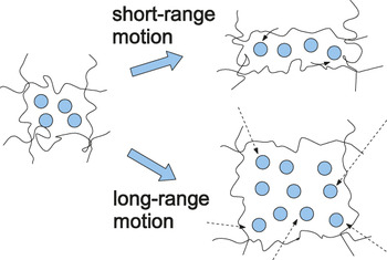
Two modes of deformation in a hydrogel.Reference Hong, Zhao, Zhou and Suo48 Short-range motion of water molecules causes the gel to change shape but not volume (viscoelasticity). Long-range motion of water causes the gel to change both shape and volume (poroelasticity).

Ceramics and glassy polymers are all Type I transducers; they are so stiff that they suffer electrical breakdown at small strains. PDMS is also Type I, while the widely used acrylic elastomer VHB (very high bond) is Type II. Analyses using this model have accounted for experimentally observed large voltage-induced deformation by pre-stretching an elastomer, by using an elastomer of interpenetrating networks, and by swelling an elastomer with a solvent.Reference Zhao and Suo42 The model has been used to design experiments that use VHB to achieve a voltage-triggered expansion of area by 1692%.Reference Keplinger, Li, Baumgartner, Suo and Bauer43
As dielectric elastomer transducers enter the consumer market, the topics of research in this area will evolve. Most current work uses two types of elastomers: VHB and PDMS. Neither was originally designed as a material for transducers. Designing new materials will require dialogue between chemists and engineers. To facilitate the dialogue, as well as to compare materials, a set of figures of merit will have to be identified. While a large number of configurations of dielectric elastomer transducers have been demonstrated,Reference Carpi, De Rossi, Kornbluh, Pelrine and Sommer-Larsen26 few have been analyzed in any detail. Existing commercial finite-element software is not coded for dielectric elastomers and has been adapted with limited functionality.Reference Wissler and Mazza44–Reference O’Brien, McKay, Calius, Xie and Anderson46 Further challenges include dissipative processes such as viscoelasticity and current leakage, and modes of failure such as rupture, electrical breakdown, and fatigue.
Hydrogels
Human body parts and the foods we consume—body parts of other species—are mostly hydrogels, mixtures of macromolecules and water. Here we focus on a class of hydrogels of particular significance to soft machines.Reference Calvert47 Long, flexible, and hydrophilic polymer chains are cross-linked into a network. The network imbibes water and swells, forming a hydrogel. The volume of water in a hydrogel often exceeds 10 times the volume of the polymer. A hydrogel has attributes of both a solid and a liquid. The network is flexible and is held together by strong bonds, enabling large and reversible deformation. Water molecules interact with each other and with polymers by weak bonds, enabling long-range transport of water and molecules dissolved in water.
For the network to deform, water molecules in the hydrogel must change neighbors, a process similar to that in pure water. Depending on the range of motion of water molecules, two modes of deformation can be distinguished (Figure 9).Reference Hong, Zhao, Zhou and Suo48 The first mode results from a local rearrangement of molecules, allowing the gel to change shape but not volume. This mode, called viscoelastic deformation, occurs over a timescale independent of the size of the sample. The second mode results from long-range migration of water, allowing the gel to change both shape and volume. This mode, called poroelastic deformation, occurs over a timescale that becomes long when the sample is large. Both modes can give rise to large deformation.
The amount of swelling of a hydrogel is affected by mechanical forces, pH, salt concentration, temperature, light, and the electric field.Reference Meng and Hu49 Gels have also been used to make stretchable batteries.Reference Kaltenbrunner, Kettlgruber, Siket, Schwodiauer and Bauer50 In many applications, structures made of hydrogels are miniaturized, alleviating a major limitation of actuation by hydrogels: the speed. The swelling rate of a hydrogel is limited by the migration of water, so that a small size leads to a fast response. Response times of some milliseconds have been demonstrated.Reference Sidorenko, Krupenkin, Taylor, Fratzl and Aizenberg6 Fast actuation can also be achieved by placing a large structure near the verge of elastic instability and then triggering the instability as a small volume of a hydrogel swell.Reference Forterre, Skotheim, Dumains and Mahadevan51, Reference Lee, Xia and Fang52
The development of hydrogel-actuated structures has also led to another major consideration. In hybrids of hydrogels and hard materials, the hydrogels must swell against the constraint of the hard materials. For example, a microfluidic valve involves a gel anchored by a rigid pillar, and the gel swells in response to a change in the pH, pushing against the walls of the fluid channel and blocking the flow.Reference Beebe, Moore, Bauer, Yu, Liu, Devadoss and Jo4 Analogous mechanisms have been used to regulate flow in oilfields.Reference Cai, Lou, Ganguly, Robisson and Suo5 It has also been demonstrated that an array of rigid rods embedded in a gel rotates when the humidity in the environment drops below a critical value.Reference Sidorenko, Krupenkin, Taylor, Fratzl and Aizenberg6 As mentioned before, diapers are designed to absorb water and swell against the weights of babies.Reference Masuda7
Despite the ubiquity of constrained swelling, the theory of constrained swelling requires substantial further work to be useful in analyzing engineering devices and natural phenomena. Developers of analysis methods face two challenges. First, swelling of a gel is affected by a large number of stimuli. Quantifying the relation between deformation and stimuli requires several important considerations. Second, when a gel is constrained by a hard material, the swelling often induces an inhomogeneous field of stress and large deformation in the gel. The magnitude of the stress is of central importance to applications such as valves and actuators. Swelling may also lead to cavities, creases, buckles, and other intriguing patterns that are hard to analyze.
Uncross-linked polymers dissolve in water and form an aqueous solution. When the aqueous solution is separated from pure water by a semipermeable membrane permeable to water but not the polymer, the solution draws water in, driven by the free energy of mixing water and the polymer. The process sets up a pressure in the solution relative to the pure water. This osmotic pressure Π is balanced by gravity and can be measured by the difference in the heights of the solution and the pure water. If the ratio of the volume of the solution to the volume of the dry polymers is denoted by J, then the osmotic pressure is characterized by the function Π(J). For a given species of polymer, the function Π(J) can be varied by changing temperature, pH, and concentrations of other solutes in water. Such variations have been studied extensively by experimental measurements and theoretical modeling.Reference des Cloizeaux and Jannink53 Commonly used models of Π(J) for neutral hydrogels and pH-sensitive hydrogels have been previously reviewed.Reference Hong, Zhao, Zhou and Suo48, Reference Hong, Liu and Suo54, Reference Marcombe, Cai, Hong, Zhao, Lapusta and Suo55
A network of covalently cross-linked polymers does not dissolve in water, but rather imbibes water. In the absence of applied forces and free from any constraint, the osmotic pressure is balanced by the elasticity of the network, and swelling is isotropic. When the gel is subject to nonhydrostatic stresses, however, swelling is anisotropic. If the applied stresses are σ1, σ2, and σ3, and the stretches are λ1, λ2, and λ3, the ratio of the volume of the hydrogel and the volume of the dry polymers is J = λ1λ2λ3. Due to swelling, the volume of the gel is larger than that of the dry polymer, J > 1. Because the density of cross-links in a gel is very low, cross-linking negligibly affects the function Π(J). That is, the function Π(J) for a hydrogel takes the same form as that for the aqueous solution. The stress-stretch relations take the formReference Cai and Suo59
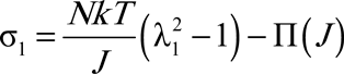
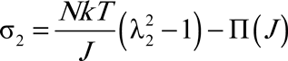
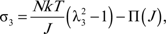
where N is the number of polymer chains per unit volume of the dry network, T is the temperature, and k is the Boltzmann constant. In hydrogels, osmotic pressure is balanced by the elasticity of the network and by the applied stresses. In the equations of state, Equations 4–6 characterize a gel in terms of a scalar N and a single-variable function Π(J).
Models of this type have been added to commercial finite-element software such as ABAQUS for neutral gels and pH-sensitive hydrogels.Reference Hong, Liu and Suo54–Reference Chester and Anand56 For example, motivated by an experimental demonstration,Reference Beebe, Moore, Bauer, Yu, Liu, Devadoss and Jo4 we have developed a finite-element method to analyze a pH-sensitive valve in a microfluidic channel.Reference Marcombe, Cai, Hong, Zhao, Lapusta and Suo55 In the channel, a pH-sensitive gel is anchored by a pillar. The valve opens when the pH of the solution in the channel is low, and closes when the pH is high. As the pH increases further, both the size of the contact and the pressure in the contact increase. At each value of the pH of the solution in the channel, the analysis assumes that the gel is in thermodynamic equilibrium with the solution in the channel. Both the pillar and the walls of the channel are taken to be rigid. They constrain the swelling of the gel and make the deformation in the gel inhomogeneous.
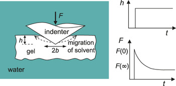
Mechanical testing of gels can be challenging. Gels are soft, and some of them are brittle and slippery. An attractive testing method involves indentation, which is easy to perform and can probe small volumes of materials.Reference Galli and Oyen57Figure 10 illustrates a particular method of indentation, known as poroelastic relaxation indentation.Reference Hu, Zhao, Vlassak and Suo58 When an indenter is pressed into a hydrogel to a fixed depth, water in the gel migrates, and the force on the indenter relaxes. The concurrent deformation and transport can be analyzed within the theory of poroelasticity. The force-relaxation curves for indenters of several types are obtained in a simple form, enabling indentation to be used with ease as a method for determining the shear modulus, Poisson’s ratio, and the permeability of the gel. Furthermore, indentation can differentiate two types of time-dependent behavior: viscoelasticity and poroelasticity. Viscoelastic relaxation time is independent of the radius of indentation, while poroelastic relaxation time is inversely quadratic in the radius of indentation.
Schematic of poroelastic relaxation indentation.Reference Hu, Zhao, Vlassak and Suo58 A disk of a hydrogel is submerged in water throughout the experiment. Prior to indentation, the gel imbibes the solvent and swells to a state of equilibrium. An indenter is then rapidly pressed into the gel and is subsequently held at a fixed depth h. The indenter causes the solvent to migrate in the gel so that the force F on the indenter decreases as a function of time (t) until the gel reaches a new state of equilibrium. Note: b, radius of contact.

Concluding remarks
Nature’s machines are mostly soft. This inspiration, along with decades of innovations in soft materials and microfabrication, has instigated the emergence of the field of soft machines. To realize functions, soft machines are often hybrids of soft and hard materials. Enabling large deformation of the hybrids requires structural designs that pay close attention to various phenomena of instability and failure. In addition to requiring stretchable electronics, soft materials also use soft active materials that are capable of large deformation in response to many types of stimuli in addition to mechanical forces. Characterizing such materials requires theories that couple large deformation with electrostatic field and mass transport. These coupled fields are often not coded in existing finite-element software and need be developed. Furthermore, the coupling of large deformation with other fields gives rise to new phenomena of instability and failure. Their discovery pushes the frontier of mechanics. The field is wide open.
Acknowledgments
The work is supported by NSF through grant CMMI-0800161 and MRSEC, by the U.S. Army Research Office through contract W911NF-09–1-0476, and by DARPA through contract W911NF-10–1-0113.