I. INTRODUCTION
Carbon nanotubes (CNTs) are promising for applications in different fields, such as electronics,Reference Aguirre, Auvray, Pigeon, Izquierdo, Desjardins and Martel1–Reference Wu, Chen, Du, Logan, Sippel, Nikolou, Kamaras, Reynolds, Tanner, Hebard and Rinzler3 fibers,Reference Andrews, Jacques, Minot and Rantell4–Reference Viry, Mercader, Miaudet, Zakri, Derré, Kuhn, Maugey and Poulin6 sensors,Reference Fukushima, Asaka, Kosaka and Aida7,Reference Bartholome, Derré, Roubeau, Zakri and Poulin8 and composites.Reference Blanchet, Fincher and Gao9,Reference Saint-Aubin, Poulin, Saadaoui, Maugey and Zakri10 In particular, CNTs are considered as one of the most convincing alternative to inorganic oxides for future transparent electrodes. As CNTs are practically insoluble in all solvents, different methods have been developed, using sonication or high shear mixing, to disperse CNTs in water or in organic solvents. CNT aqueous dispersions can be obtained using surfactants and sonication.Reference Shen, Curran, Xu, Rogelj, Jiang, Dewald and Pietrass11 Nevertheless, these methods are known to damage CNTs, creating defects on the walls of nanotubesReference Lu, Lagon, Chen, Green and Harris12 and shortening them.Reference Lucas, Zakri, Maugey, Pasquali, vd Schoot and Poulin13,Reference Pagani, Green, Poulin and Pasquali14 An alternative method known as reductive dissolution has been developedReference Pénicaud, Poulin, Derré, Anglaret and Petit15–Reference Vigolo, Hérold, Marêché, Bourson, Margueron, Ghanbaja and McRae19 in which CNTs are reduced by potassium naphthalide in Tetrahydrofuran (THF).Reference Petit, Mathis, Journet and Bernier20 A negatively charged CNT salt is obtained, which is spontaneously soluble in polar aprotic solvents, such as Dimethyl sulfoxide (DMSO). No sonication is used. It has been shown that the reductive dissolution individualizes nanotubes without damaging them.Reference Voiry, Drummond and Penicaud21,Reference Pénicaud, Dragin, Pécastaings, He and Anglaret22 Here we show that transparent conducting films (TCFs) prepared from CNT solutions obtained by reductive dissolution have far better performances than films prepared from aqueous, sonication-aided dispersions. The study is focused on understanding the effects of the reductive dissolution on film electrical performances and on highlighting the key parameters to control these performances. Nanotube length appears to be a key parameter to tune the sheet resistivity of the films. Moreover, it has been shown that indium tin oxide (ITO) can be damaged under acidic conditions.Reference Senthilkumar, Mathiyarasu, Joseph, Phani and Yegnaraman23 In this article, we show that the electroactivity of CNT films, in addition to their better chemical resistance to acids, allows their use in applications where ITO is unsuitable.
Among different alternative materials,Reference Lee, Wang, Kim and Hahn24 such as grapheneReference Bae, Kim, Lee, Xu, Park, Zheng, Balakrishnan, Lei, Kim, Sng, Kim, Kim, Özyilmaz, Ahn, Hong and Iijima25 and metal electrodes,Reference Kang, Kim, Kim and Guo26 CNTs are a promising material for the replacement of ITO used in current electronic devices.Reference Hecht, Hu and Irvin27,Reference Kumar and Zhou28 Indeed, ITO has some limitations, such as its brittleness, high cost, and limited supply. New materials with comparable performances are actively sought after. Those materials should ideally exhibit a transmittance higher than 80% and a surface resistivity of 10 Ω/sq.Reference Minami and Miyata29 TCFs are one of the possible applications for CNTs as it was shown first by Rinzler et al.Reference Wu, Chen, Du, Logan, Sippel, Nikolou, Kamaras, Reynolds, Tanner, Hebard and Rinzler3 CNT thin films can be prepared by different techniques, such as by filtration technique. This method has the advantage of being easily performed and to produce homogeneous network of randomly distributed CNTs. In 2004, Rinzler et al. produced CNT films having a surface resistivity of 30 Ω/sq for 90% transmittance using laser ablation single-walled carbon nanotubes (SWCNTs).Reference Wu, Chen, Du, Logan, Sippel, Nikolou, Kamaras, Reynolds, Tanner, Hebard and Rinzler3 Grüner et al. developed a similar method in 2006.Reference Zhou, Hu and Grüner30 In their study, CNT network was transferred by stamping CNTs from filtration membrane on flexible substrates. These CNT films showed a surface resistivity of 120 Ω/sq for 70–80% of transmittance. Pasquali et al. worked on a draw–roll method and obtained CNT films with a surface resistivity of 600 Ω/sq for 90% of transmittance.Reference Dan, Irvin and Pasquali31 This method is one of the most promising methods for future scale-up.Reference Lima, de Andrade, Bergmann and Roth32 Other techniques, such as dip coating, spray coating, electrodeposition, or chemical vapor deposition (CVD), have been studied and display interesting features in terms of achieved performances and scalability.Reference Lima, de Andrade, Bergmann and Roth32–Reference Pint, Xu, Pasquali and Hauge34 In particular, using very long nanotubes, Pasquali et al. have obtained films by dip coating that exhibit a 100 Ω/sq resistivity for 90% transmittance.Reference Mirri, Ma, Hsu, Behabtu, Eichmann, Young, Tsentalovich and Pasquali35
For clarity, in this article, we call rd-CNTs, CNTs processed by reductive dissolution to prepare the solutions and then the films, whereas the term ad-CNTs are used to describe CNT aqueous dispersions. Using routinely available CNTs from commercial source (MWCNTs from Arkema, FWCNTs (Elicarb™) from Thomas Swan and SWCNTs (CoMoCAT™) from SWeNT), we show that the reductive dissolution avoids cutting the tubes and allows to obtain better performing TCFs, with surface resistance as low as 200 Ω/sq at 80% transmittance reachable for CoMoCAT SWCNTs.
II. TCFs: RESULTS
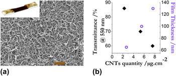
The so-called membrane filtration method allows the thickness of CNT films to be controlled by varying the volume of filtered solution. As shown in the scanning electron micrograph of Fig. 1, CNT networks are homogeneous. Moreover, measurements by x-ray photoelectron spectroscopy of film surface show that the rinsing process is efficient to obtain clean CNTs, indeed, neither potassium nor surfactant was found on the surface. Atomic force microscopy (AFM) measurements have been performed to characterize the thickness of the films by measuring the depth of a straight scratch made into them [see inset to Fig. 1(a)]. Varying the quantity of filtered solution, the thickness and, therefore, the transmittance of the CNT films can accurately be controlled. Using multiwalled carbon nanotubes (MWCNTs), film thickness can be tuned between 60 and 130 nm for a transmittance between 85 and 60%. Thickness of few-walled carbon nanotubes (FWCNTs) films was found to vary between 30 and 60 nm for a transmittance from 80 to 60%. The difference from MWCNTs suggests that FWCNTs are more densely packed for the same transmittance.
(a) SEM picture of a MWCNT film. Scale bar is 0.5 micrometer. Inset: AFM image of a scratch made to measure thickness. The actual thickness of this film is 40 nm while the width of the scratch is 20 micrometer. (b) Transmittance and thickness of MWCNT films versus CNT quantity.

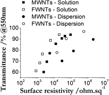
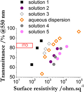
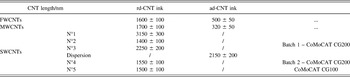
Electrical performances of CNT TCFs have been then investigated. Film transmittance versus the surface resistivity is plotted in Fig. 2. Influence of the reductive dissolution route on film performances can be compared to that of the aqueous dispersion method, for MWCNTs and FWCNTs. Considering FWCNT films, surface resistivity is much lower using the solvent method than the aqueous method. At 80% of transmittance, the surface resistivity is about 2500 Ω/sq for films made with rd-FWCNTs, which is an order of magnitude lower than the surface resistivity (about 20,000 Ω/sq) of ad-FWCNT films. A similar result is obtained for MWCNT films, rd-MWCNT films have a surface resistivity of 5000 Ω/sq at 80% of transmittance compared to a surface resistivity of about 100,000 Ω/sq at the same transmittance for ad-MWCNT films. Moreover, we can observe that electrical performances of films depend on the type of CNTs. As shown in Fig. 2, using the same solution preparation, FWCNT films have better electrical performances than MWCNT films at the same transmittance. As sonication is known to shorten CNTs,Reference Pagani, Green, Poulin and Pasquali14,Reference Badaire, Poulin, Maugey and Zakri36 CNT length was investigated and compared for both solution and dispersion methods. CNT length can be measured by dynamic light scattering (DLS) using a method detailed in the literature.Reference Pagani, Green, Poulin and Pasquali14,Reference Badaire, Poulin, Maugey and Zakri36,Reference Shetty, Wilkins, Nanda and Solomon37 Results show that ad-CNTs are shorter than rd-CNTs. rd-FWCNTs are 1.6 ± 0.1 µm long in organic ink compared to 500 ± 50 nm for ad-FWCNTs in aqueous inks. rd-MWCNTs are 1.7 ± 0.1 µm long in organic inks. They are much shorter in aqueous dispersions, with a length of 320 ± 50 nm. These results show that the reductive dissolution is efficient at maintaining long CNTs in liquids opening thereby an important route to improve the properties of CNT films. We stress that no sonication was used in the above experiments for nanotubes treated by reductive dissolution. This is why their length is greater than that of nanotubes dispersed in water. This holds for all types of CNTs: MWCNTs, FWCNTs and SWCNTs. Effect of length and relation with electrical performances of CNT films is discussed below, thanks to the study of SWCNT films. These films were prepared as described above with different batches of CNTs. A first batch of CoMoCAT CG200 CNTs has been used to prepare three solutions (from number 1 to 3) by the solvent method and one aqueous dispersion. For each solution, 64 mg of raw CNTs were used to prepare a CNT potassium salt that was then dissolved to form ca 8 mL of solution. In spite of originating from the same batch, the resultant solutions have been observed to differ because of the heterogeneity of the raw powder. As seen latter, the variability in the raw powder allowed solutions with nanotubes of different lengths to be investigated. The CNTs in solutions differ in their average length by almost a factor 2. A second batch of CoMoCAT CG200 has been used to prepare solution 4 and a batch of CoMoCAT CG100 to prepare solution 5—both by solvent method. All these inks were done to investigate the reproducibility of electrical performances of SWCNT films. First, using rd-SWCNT solution, good conductive films are obtained. The best films, made with solution 1, have a surface resistivity of 210 Ω/sq at 80% transmittance, which approach ITO performances by roughly one order of magnitude. Nevertheless, Fig. 3 clearly shows that a wide range of surface resistivity is obtained using the same kind of SWCNTs, from 210 to 10,000 Ω/sq at 80%, fact that we ascribe to the heterogeneity of the CNT batch use and the different average CNT lengths in each solution. Following the results obtained for MWCNT and FWCNT solutions and films, DLS measurements have been performed to measure CNT average length. The obtained results are shown in Table I. A link between CNT length and electrical performances of films can clearly be seen. The most conductive films (R sq = 210 Ω/sq, T = 80%) have been prepared with the longest CNTs with a length of about 3.1 µm. The shorter the CNTs, the more resistive are the CNT films. As shown in Fig. 3, results can be separated in three groups: the most conductive films (represented by squares), the most resistive ones (represented by circles), and the intermediate ones (represented by rhombs). As has been amply documented in the literature,Reference Pénicaud, Petit, Fischer and Monthioux38,Reference Khoerunnisa, Morelos-Gomez, Tanaka, Fujimori, Minami, Kukobat, Hayashi, Hong, Choi, Miyahara, Terrones, Endo and Kaneko39 doping could further improve conductivity of the films but has not been attempted here.
Transmittance of FWCNT and MWCNT films versus their surface resistivity.

Transmittance of CNT films versus their surface resistivity. The results are represented in three groups according to the CNT length. Squares correspond to the longest CNTs, about 3.1 µm long. Rhombs correspond to an intermediate length, about 2.2 µm long, and circles represent the shortest CNTs, about 1.5 µm long.

CNT length measured by DLS for the different inks.

III. TCFs: DISCUSSION
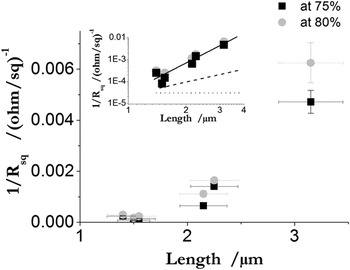
Results show that the surface resistivity of the CNT films depends strongly on the CNT length [Fig. 4]. This dependency suggests that the conductivity is limited by the contact resistance of the nanotube junctions, as observed in several other nanotube-based composites and transparent electrodes.Reference Song, Yang, Kim, Kanoh and Kaneko33,Reference Li, Thostenson and Chou40–Reference Yang, Kong, Jung, Baek, Han, Oh and Jung42 Indeed, when the nanotubes are sufficiently long, their resistance exceeds the resistance of a contact. In this regime, the conductivity is not anymore expected to depend on the length of the nanotubes.Reference Hecht, Hu and Grüner43 The conductivity is just expected to depend on the density of nanotubes present in the films. By contrast when nanotubes are short, the conductivity can become length dependent. In particular, close to the percolation threshold, it has been shown that the conductivity is expected to scale as ∼L 2.5.Reference Hecht, Hu and Grüner43 Note that this is an upper bound only valid close to percolation. At greater concentrations, lower exponents can be expected. In this regime, one has to consider the density of contacts. But the latter is still independent on the nanotube length as long as the volume fraction is kept constant.Reference Chen, Chen, Hough, Islam and Yodh44 In brief, depending on the CNT concentration and length, variations of conductivity are expected to vary between scaling laws with exponents from 0 to 2.5.Reference Hecht, Hu and Grüner43 Our experiments are in disagreement with such expectations. They are also in disagreement with previous studies in which the nanotubes were sorted by centrifugation instead of being sorted by length using the sonication method to shorten them.Reference Simien, Fagan, Luo, Douglas, Migler and Obrzut45 If the data would be fitted by a scaling law, the conductivity would approximately scale as ∼L 4 [Fig. 4]. This large variation indicates that the conductivity is limited by the contact resistance between nanotubes, meaning that the nanotubes are not yet long enough so that the film conductivity becomes independent on the nanotube length. But geometrical effects alone cannot explain the present results as the data are outside the range defined by the limiting cases of near percolated networks and constant conductivity.
TCF Conductivity versus CNT length for two sets of TCF transmittance, the inset shows on a log–log scale the experimental data, experimental trend in L 4 (black line), theoretical behaviors for constant conductivity in L 0 (dotted line), and for length dependent conductivity in L 2.5 (dashed line).

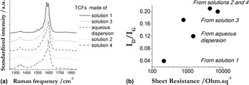
Other effects have, therefore, to be considered. The main deviations from the simplest expectations detailed above are likely due to intrinsic features of the nanotubes. In particular, the density of structural defects is expected to strongly alter the conductivity of the films. Indeed, defects play an important role on the conductivity, since they alter the π conjugation of the nanotubes. The presence of defects has been confirmed by Raman experiments. As shown in Fig. 5, the ratio I D/I G increases with the sheet resistance of the TCFs, confirming that the most conductive films are obtained with the less defective nanotubes. Even a slight degradation of the CNT structure can result in a substantial decrease of the conductivity and can likely explain substantial deviations from the length dependence expected for random networks of homogeneous CNTs.
(a) Raman spectra of the different TCFs and (b) I D/I G ratio versus sheet resistance for the TCFs.

IV. ELECTROACTIVITY OF CNT FILMS
In this section, CNT films are studied as a substitute to ITO electrodes in electrochemical applications. Several studies have already shown that CNTs are electroactive and can be used as electrochemical sensors, for example, to detect insulin,Reference Snider, Ciobanu, Rue and Cliffel46 ammonia gas,Reference Nguyen, Phi, Phan, Vu, Nguyen Duc and Fossard47 or traces of heavy metals.Reference Xu, Zheng, Yang, Liu and Jin48 CNT catalytic activity has also been studied in dye-sensitized solar cell.Reference Grätzel49–Reference Kavan, Marcaccio and Paolucci52 ITO, on the other hand, is widely used as electrode material under mild conditions, in particular in organic media,Reference Alam and Cameron53 while it is known to be unsuitable under more extreme conditions, as for instance in aqueous solutions, at low pH and negative potentials where it rapidly undergoes an irreversible degradation with a severe loss of conductivity, transparency, and electroactivity.Reference Mirri, Ma, Hsu, Behabtu, Eichmann, Young, Tsentalovich and Pasquali35,Reference Stotter, Show, Wang and Swain54 Thus, a comparison of CNT films and ITO as electrode materials has been performed at low pH, using a standard redox couple 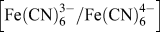 $\left[ {{{\rm{Fe}}\left( {{\rm{CN}}} \right)_6^{3 - } } \mathord{\left {\vphantom {{{\rm{Fe}}\left( {{\rm{CN}}} \right)_6^{3 - } } {{\rm{Fe}}\left( {{\rm{CN}}} \right)_6^{4 - } }}} \right. \kern-\nulldelimiterspace} {{\rm{/Fe}}\left( {{\rm{CN}}} \right)_6^{4 - } }} \right]$ to study their electroactivity. Results showed that CNT films can be used in acidic media where ITO is damaged.
rd-CNT films made with SWCNT from both SWeNT (CoMoCAT) and CCNI origin were used to prepare the electrodes, and Fig. 6 shows cyclic voltammograms of potassium ferrocyanide measured with two different CNT films. The high symmetry of the cyclic voltammetry (CV) curves along with the linear dependence of the peak currents on ν1/2 and the invariance of peak potentials with the scan rate (not shown) highlight the expected Nernstian behavior of such a redox couple on the CNT electrodes. Such electrodes are, therefore, virtually indistinguishable from ITO, whose behavior is also shown for comparison in Fig. 6.
Cyclic voltammograms of the  ${{{\rm{Fe}}\left( {{\rm{CN}}} \right)_6^{3 - } } \mathord{\left {\vphantom {{{\rm{Fe}}\left( {{\rm{CN}}} \right)_6^{3 - } } {{\rm{Fe}}\left( {{\rm{CN}}} \right)_6^{4 - } }}} \right. \kern-\nulldelimiterspace} {{\rm{/Fe}}\left( {{\rm{CN}}} \right)_6^{4 - } }}$ couple measured with an ITO film, two (CoMoCAT) CNT films as working electrodes. “NT1” and “NT2” films had respective surface resistivities of 94 and 212 Ω/sq. The inset shows the linear evolution of the anodic
 $\left( {I_{\rm{p}}^{\rm{a}}} \right)$ peak currents as a function of ν1/2 for NT1 film (red dots) and ITO (black dots).

The effect of cathodic treatment in acidic conditions on the electroactivity was investigated by electrochemical impedance spectroscopy (EIS). Figure 7 shows the spectra measured at the CNT film, at 0.18 V, i.e., the standard potential of the [Fe(CN)63−/Fe(CN)64−] redox couple. The electrodes were treated with 10 polarization cycles from 0.2 to −1.2 V at a scan rate of 0.1 V/s in acidic aqueous solutions. In the case of CNT films, the above treatment resulted in an improved electroactivity than in the pristine films. A significant decrease of the charge transfer resistance, from ∼600 to <320 Ω cm−2, is in fact observed after treatment at pH 5 and even larger at pH 3. Such a behavior may be attributed to the removal of defects, such as oxidized sp 3 groups onto the CNT surface, during the cathodic treatment that would improve its electrocatalytic performance. The effect of the surface state upon the charge transfer kinetics on CNT electrodes has been the subject of numerous investigations, which have shown that the electrochemical pretreatments are, in particular, able to change the electronic properties of the carbon material producing different electrocatalytic behaviors.Reference Valentini, Amine, Orlanducci, Terranova and Palleschi55 In addition, the pristine CNT films show values of the double layer capacitance typical for electrolytic aqueous solutions (15–20 μF cm−2). Although the above treatment results in an increase of the charge transfer resistance, no significant difference was observed in the double layer capacitance. This is a further indication that the cathodic treatment improved the kinetics of the electrochemical reaction maintaining unchanged the morphology of the electrode surface.
(a) EIS of (CCNI) CNT film and (b) EIS of ITO glass. For both electrodes, EIS has been done before any treatment and after acidic treatment at pH 5 and pH 3, in 0.1 M KCl + 1 mM  ${{{\rm{Fe}}\left( {{\rm{CN}}} \right)_6^{3 - } } \mathord{\left {\vphantom {{{\rm{Fe}}\left( {{\rm{CN}}} \right)_6^{3 - } } {{\rm{Fe}}\left( {{\rm{CN}}} \right)_6^{4 - } }}} \right. \kern-\nulldelimiterspace} {{\rm{/Fe}}\left( {{\rm{CN}}} \right)_6^{4 - } }}$ solution. A treatment is 10 cathodic polarization cycles from 0.2 to −1.2 V at 0.1 V/s. Pictures of ITO substrates from the left to the right: before treatment and after treatment at pH 5 and pH 3. ITO surface changes color when exposed to the treatment; the circle part is due to the electrochemical cell design. Inset to a: the cyclic voltammogram of the
 ${{{\rm{Fe}}\left( {{\rm{CN}}} \right)_6^{3 - } } \mathord{\left {\vphantom {{{\rm{Fe}}\left( {{\rm{CN}}} \right)_6^{3 - } } {{\rm{Fe}}\left( {{\rm{CN}}} \right)_6^{4 - } }}} \right. \kern-\nulldelimiterspace} {{\rm{/Fe}}\left( {{\rm{CN}}} \right)_6^{4 - } }}$ couple measured with the film used for EIS. This film had a surface resistivity of 189 Ω/sq.

By contrast, in the case of the ITO electrode, the same treatment brought about a strong increase of the charge transfer resistance and of the capacitance of the double layer, both associated to the known instability of such material at negative potentials and under acidic condition that, after prolonged treatment, leads to its complete inactivity, as shown in Fig. 7(b).
V. CONCLUSIONS
Uniform and homogeneous TCFs have been made by filtration of different CNT solutions prepared either by the reductive dissolution route or by the aqueous dispersion technique. CNT length appears as a key parameter to control the electrical properties of the CNT TCFs. Avoiding sonication and high shear mixing, the reductive dissolution preserves the pristine nanotube length. It is thus a choice method to prepare TCFs and other devices/composites where CNT length is crucial. Of course, this is not the sole important factor. Defects induced by sonication, high shear mixing, covalent functionalization, or any other relatively aggressive method to disperse CNTs can further downgrade the properties of TCFs. This is why the reductive dissolution method used in this work outperforms by far the conventional sonication and surfactant assisted dispersion method, beyond the simple advantage of achievement of longer CNTs. Indeed, CNT defects and metallic/semiconductor CNT ratio add a synergetic effect that may explain the strong dependency of the TCF sheet resistance observed with the CNT length. Furthermore, the CNT films can profitably substitute ITO as electrode materials, especially in acidic conditions, where CNTs show a superior stability than ITO. The CNT films’ electroactivity improves in fact at negative potentials, a possible doping effect from the acidic medium.
VI. EXPERIMENTAL
A. Materials
The CNTs used to make films are all produced by CVD. Elicarb CNTs from Thomas Swan are CNTs composed of one to three walls. They are called FWCNTs. MWCNTs were produced by Arkema. SWCNTs (CoMoCAT) were purchased from SWeNT. Different batches of SWCNTs have been used (CG200 and CG100). SWCNTs from CCNI have been used for electrochemical experiments. Sodium cholate purchased to Sigma–Aldrich is used as surfactant to prepare aqueous dispersions. DMSO is used as organic polar solvent to dissolve CNT salts in the process of reductive dissolution and was purchased from Sigma–Aldrich. This solvent was filtered over a 20 nm pore size membrane before use. THF is used to prepare the reductive solution and was purchased from Sigma–Aldrich. All organic solvents used during the reductive dissolution process are dried over alumina before use under inert atmosphere.
B. Aqueous dispersions and their subsequent films (ad-CNTs)
Aqueous dispersions of CNTs were prepared by ultrasonication with sodium cholate as surfactant. FWCNTs and MWCNTs dispersions were prepared at 0.3% wt of CNTs, and SWCNT dispersions were prepared with only 0.1% wt of CNTs. In all cases, the ratio CNT: surfactant is of 1:1 in weight. The concentration of sodium cholate is maintained near the critical micellar concentration to allow a good dispersion, but below a concentration where depletion phenomenon can occur to avoid further interactions between CNTs, as shown by Maillaud et al.Reference Maillaud, Zakri, Ly, Pénicaud and Poulin56 The SWCNT dispersion required a slight centrifugation (30 min at 1800 g) to remove the residual aggregates. A good dispersion of CNTs without any aggregates visible under optical microscope is obtained after an hour of sonication at a power of 25 W and centrifugation. Then CNT dispersions were filtered on cellulose membranes to obtain thin films. Finally, the films were transferred on different substrates, such as PET or glass substrates, using the method described previously by Martel et al.Reference Aguirre, Auvray, Pigeon, Izquierdo, Desjardins and Martel1
C. Solutions and films by solvent method (rd-CNTs)
The same CNTs were used to prepare true solutions as described previouslyReference Pénicaud, Poulin, Derré, Anglaret and Petit15 using the reductive dissolution method of CNTs in a polar solvent, such as DMSO. The first step consists in the reduction of CNTs by a solution of potassium naphthalenide in THF.Reference Petit, Mathis, Journet and Bernier20 The stoichiometry of the salt is controlled at this step and kept at KC10. After drying, 8 mg of salt is added to 1 mL of DMSO and stirred at room temperature overnight. A centrifugation (2500 g, 1 h) led to solutions with concentrations of 2 mg/mL of FWCNTs and 1.7 mg/mL of MWCNTs.
rd-CNT films were prepared by filtration on alumina membranes and then transferred on substrates.Reference Minami and Miyata29 The whole process has to be realized under inert atmosphere until the filtration is done. Only the transfer is performed in ambient air. It consists in the dissolution of the alumina membrane in a sodium hydroxide bath. While the membrane is removed, the film is floating on the liquid of the bath. After rinsing with distilled water to neutralize the bath, a substrate is immersed under the rd-CNT film, which is gently deposited on the substrate, by removing water. Finally, the film is dried at 50 °C overnight.
D. DLS measurements
Average length of CNTs was measured by DLS. The experiments were performed at 20 °C using a continuous diode laser Excelsior Spectra-Physics at a wave length of 644 nm with a maximum power P = 100 mW and a Brookhaven BI-90000AT digital autocorrelator (Holtsville, NY) to compute the scattered intensity time autocorrelation function. A routine method was developed by Badaire et al.Reference Badaire, Poulin, Maugey and Zakri36 to calculate the length of CNTs based on Broersma's relations for rigid rods.Reference Broersma57,Reference Broersma58
E. Scanning electron microscopy (SEM)
SEM observations were performed with a JEOL 6700F scanning electron microscope (JEOL, Tokyo, Japan) operating at 5 kV. Samples were coated with a nm-thick layer of gold palladium (10%) with a SC7620 Sputter coater (Quorum Technologies, Laughton, East Sussex, UK) or JFC1200 Fine coater (JEOL, Tokyo, Japan) before analysis.
F. Electrical measurements
Surface resistivity of FWCNT and MWCNT films has been measured using a two contact method. Surface resistivity of SWCNT films has been measured using a four contact method. For this characterization, four gold electrodes are sputtered through a mask over CNT films. Geometry of the electrodes is well controlled to allow a good comparison of the surface resistivity of CNT films.
G. Electrochemistry
Electrochemical experiments were performed with a three electrode cell controlled by a 650D electrochemical workstation from CH Instrument, Inc. using an Ag/AgCl electrode and a platinum wire as respectively reference electrode and counter electrode. Working electrode was either CNT films or ITO glass depending on the experiments.
A cathodic polarization was performed from 0.2 to −1.2 V at pH 5 and pH 3 in buffered solutions to treat CNT films and ITO glass. CV and EIS were carried out in aqueous solution containing KCl at 0.1 M as supporting electrolyte and a redox couple  ${{{\rm{Fe}}\left( {{\rm{CN}}} \right)_6^{3 - } } \mathord{\left {\vphantom {{{\rm{Fe}}\left( {{\rm{CN}}} \right)_6^{3 - } } {{\rm{Fe}}\left( {{\rm{CN}}} \right)_6^{4 - } }}} \right. \kern-\nulldelimiterspace} {{\rm{/Fe}}\left( {{\rm{CN}}} \right)_6^{4 - } }}$ at 1 mM, before and after each treatment to control the effect of the treatment. The EIS was performed from 0.1 to 106 Hz, at 180 mV corresponding to the half-wave potential of the redox couple.
ACKNOWLEDGMENTS
AC thanks Arkema and l’Association Nationale pour la Recherche et la Technologie (ANRT) for a PhD grant. Support from the Agence Nationale de la Recherche (IMPEC Project) is acknowledged. AP thanks Dr H. Saadaoui for the inset of Fig. 1(a) and the Aquitaine region for a grant to support collaboration with the Emilia Romagna region. This work has been performed within the framework of the GDR-I 3217 “graphene and nanotubes”.