I. INTRODUCTION
Continuous-wave (CW) radar architectures have been widely used in many applications, including aviation, navigation, automotive industry, meteorology, and police speed guns [Reference Holger1–Reference Yanovsky3]. In recent years, they have also been applied in healthcare, aiming at vital signs monitoring [Reference Mostafanezhad, Boric-Lubecke and Lubecke4–Reference Guochao, Changzhan, Inoue and Changzhi6] and fall detection [Reference Mercuri, Schreurs and Leroux7–Reference Karsmakers, Croonenborghs, Mercuri, Schreurs and Leroux11], both in home and clinical environments. In this work, we aim at developing a system for indoor tagless localization of people in home and clinical environments. Such radar applications require high performance while involving, at the same time, simple, compact, and low-cost architectures. The demand for low cost makes a monostatic architecture particularly appealing for designing system.
A monostatic structure, that integrates a single antenna as transmitter and receiver simultaneously, will result in a more compact solution considering also that multiple sensors should be integrated in an indoor wireless sensor network in order to cover the full living environment of the user. However, a major challenge in designing a monostatic CW radar is to detect the power level of the target's reflections, in the order of a nano Watt or less in presence of a leakage signal generated by the poor isolation between transmitter and receiver and by the reflected signal due to the antenna mismatch, which saturates and desensitizes the receiver. Since the radar resolution depends on the radar total bandwidth, the undesired leakage must be reduced below a practical value over the whole radar bandwidth. As demonstrated by the authors in [Reference Mercuri10] using a bistatic configuration, to cover a room of 5 × 5 m2, the unwanted reflection should be maximally −35 dB over the whole radar bandwidth. Reducing further this value will result in a larger radar detection range. It should be noted that, in pulse radar, the undesired reflection can be avoided by time gating. However, this solution requires high-speed analog-to-digital converters (ADCs) and high-level processors, which is not preferable in low-cost indoor mass market applications. Moreover, time gating limits the detection of very close targets, which is undesired in indoor environments, where it is likely to have a person standing close to the radar.
Academic investigations on monostatic pure CW radars involving passive leakage cancelers are reported in [Reference Songcheol12–Reference Jeong-Geun, Sangsoo, Sanghoon, Jae-Woo and Songcheol15]. However, these solutions have been demonstrated only for narrowband systems. Other works on narrowband CW radar involving an active leakage canceler are presented in [Reference Gonzalez, Grajal, Asensio, Madueno and Requejo16, Reference Kuo, Wang, Wang, Chuang and Lin17]. The first, developed to demonstrate only the reduction of the leakage in a narrow band, presents a much more complex architecture than the solution presented in this manuscript, involving four couplers and a circulator. Moreover, this prototype does not include both the receiver and the antenna, which have a strong contribution in the unwanted leakage reflection. Also, this architecture requires another coupler to send a copy of the transmitted signal to the receiver. In addition, it requires an In-phase and Quadrature (IQ) mixer to generate the cancelation signal. Also [Reference Kuo, Wang, Wang, Chuang and Lin17], used to monitor vital signs, presents a complex architecture, involving two mixers, four couplers, a ferrite circulator, and a horn antenna, making the system non-compact. Other leakage canceler investigations for narrowband applications are reported in [Reference Hyoungsoo, Sanghyun, Sungyong and Kil-Hoon18, Reference Jae-Young, Chan-Won and Kyung-Whan19]. The first considers a transmitter leakage canceler circuit for full-duplex wireless communication. However, this system does not include the receiver and the antenna. The second presents a leakage suppression front-end for UHF radio-frequency identification (RFID) reader, whose architecture, different from the one presented in this paper, was demonstrated for a narrowband system. Other works concern only narrowband [Reference Saavedra and Zheng20–Reference Ding-Jie, Jing-Lin and Huei24] and wideband [Reference Shih-Chieh, Jhih-Yu, Kun-You and Huei25] quasi-circulators. However, these works do not consider the mismatch between the antenna and the circulator, whose problem becomes more emphasized in wideband applications.
In this work, a complete monostatic stepped-frequency continuous-wave (SFCW) radar integrating a wideband tunable leakage canceler is presented and discussed. The system allows tagless monitoring of persons, meaning without any use of RFID tag on the person. This represents a potential Ambient Assisted Living (AAL) technology, where indoor localization represents a potential objective, even if it is secondary to vital signs monitoring and fall detection. In fact, depending on his/her the position in the room, it is possible to foresee which daily activity a person is doing and by that establish the well-being of elderly people. Moreover, the proposed architecture presents a different and more compact solution compared with the systems reported in literature [Reference Songcheol12–Reference Jae-Young, Chan-Won and Kyung-Whan19]. Furthermore, its feasibility has been demonstrated for over 1 GHz of bandwidth, while considering also the antenna mismatch problem. It should be specified that the proposed architecture is intended for indoor medical applications and, therefore, the situation and the challenges are different than the ones experienced in other applications, such as aviation, navigation, automotive industry, industrial plant facilities, and meteorology, e.g., the poor reflectivity of a person compared with objects, compactness, low costs. References [Reference Mastela, Reindl, Wiebking, Kawalkiewicz and Zander26–Reference Agethen29] report two-antenna industrial radar systems. References [Reference Sai and Kastelein30, Reference Xianzhong, Fengmei, Qingwen and Yifang31] report single-antenna SFCW radars for industrial applications, which involve high-directive and bulky antennas. Due to the high antenna directivity and high target's reflectivity, the target information can always be distinguished without involving any leakage canceler. In [Reference Klein, Faassen, Kulke and Rusch32, Reference Vinci33], single-antenna CW radar have been proposed for small distance measurements and vibration monitoring in industrial environments. In [Reference Mastela, Reindl, Wiebking, Kawalkiewicz and Zander26–Reference Vinci33] the leakage problem is not mentioned and the target's reflection is sufficient to be resolved by the unwanted reflections.
Although the proposed approach is demonstrated on a SFCW radar, the same feedforward canceler technique and architecture is suitable also for an FMCW (frequency-modulated continuous-wave) radar. It should be specified that the proposed radar implementation is capable also of fall detection, implying that it is sufficient to determine only the target's speed [Reference Mercuri10, Reference Karsmakers, Croonenborghs, Mercuri, Schreurs and Leroux11]. However, this operation can be performed involving a traditional CW monostatic radar. The latter, in fact, requires a narrowband architecture, such that the related leakage can be easily reduced by an appropriate passive microwave design [Reference Songcheol12–Reference Han Lim, Won-Gyu, Oh and Jong-Won14]. For that reason, this work focuses only on tagless localization.
In Section II, the operational principle and the radar architecture are presented and detailed. The experimental results are shown in Section III, and conclusions are drawn in Section IV.
II. METHOD AND CIRCUIT
In this Section, the operation principle of the proposed radar system is explained. In particular, the overall system and the feedforward canceler principle are described in Subsection (A), while the radar system is presented in Subsection (B).
A) System description and feedforward canceler
Figure 1 shows the block diagram of the proposed monostatic radar sensor. A radar waveform T(t) is applied to the input port of coupler 1. Part of this signal is delivered to port 2 and feeds the gain block 1 whose output is connected to port 1 of coupler 2. Port 2 of coupler 2 is connected to the antenna while port 3 is connected to the gain block 3 before feeding the local oscillator (LO) mixer's port. The echo reflected by the target is collected by the antenna and is coupled to port 4 of coupler 2. The latter is amplified by the low-noise amplifier (LNA) and the gain block 2. The signal Γ at this port consists of the target's reflection, containing speed and absolute distance information, and of the unwanted leakage's reflection generated by the coupler's isolation and by the mismatch between the antenna and its feeding line. The unwanted reflection, whose magnitude is much stronger than the target's echo and which varies over frequency, should be eliminated by the leakage canceler network, that consists of a variable gain amplifier (VGA) and a phase shifter. For that reason, part of the input SFCW signal T(t) is coupled to port 3 of coupler 1. This signal is sent to the leakage canceler that is tuned in order to generate a signal that presents the same magnitude but out-of-phase of the unwanted reflection. The resulting signal is added by a combiner to the reflection present at port 4 of coupler 2. The result of this operation produces ideally a signal containing only the target's information that is then mixed with a copy of the transmitted signal to generate the baseband monitoring signals. It should be specified that the purpose of the gain block 1 is to stop the reflections coming from the antenna and coupler 2 that can influence the leakage canceler network.
Block diagram of the monostatic radar sensor.

B) Radar system
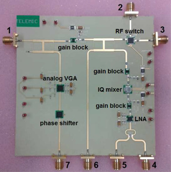
The monostatic SFCW radar has been designed on a single printed circuit board (Rogers RO4350B substrate) with a size of approximately 10(l) × 10(w) × 0.5(t) cm3 (Fig. 2). It integrates three gain blocks, a LNA with a noise figure of 1.8 dB and a gain of 19.5 dB, an IQ mixer, an RF switch, an analog VGA, and an analog phase shifter. The serial numbers and key specifications of the commercial components are specified in Table 1. The last two devices form the leakage canceler network. Two identical symmetric wideband branch-line couplers have been designed to operate in the radar operational frequency band between 5.8 and 7 GHz. These second-order couplers have been optimized to present a binomial response type. This solution allows having better performance compared with other response characteristics. Figure 3 shows the measured S-parameters of a branch-line coupler fabricated on the same substrate used for designing the radar. These results confirm the operation of the coupler for the targeted radar application.
Monostatic radar architecture.

Measured S-parameters of the wideband branch-line coupler.

Key specifications of the commercial components.

The RF switch has been integrated to connect the radar antenna, at port 2, alternately with the radar transceiver and with port 3. Although in this current design the switch could seem meaningless, the idea is that in the future a Zigbee module and a microcontroller will be integrated in this proposed architecture such that the baseband signals can be acquired, digitized, and transmitted wirelessly by the radar antenna to a base station to perform data processing, as already demonstrated with the bistatic radar architecture by the authors in [Reference Mercuri10]. For that reason, the switch has been integrated in the board in order to take into account also the undesired reflection generated by the switch's return loss in designing the leakage canceler network.
Each time a new frequency of the radar waveform is applied to port 1, a direct current (DC) voltage is applied both to the VGA and to the phase shifter in order to generate at port 7 a signal with the same magnitude but out-of-phase with the unwanted reflection present at port 6. Since the leakage and transfer characteristics of the leakage canceler change with frequency, different sets of voltages have to be determined at each of the operating frequencies. During the radar operation, the values are stored as a LUT (look-up table), and be set accordingly to the varying frequency. However, they should be first determined by the calibration. The latter can be perceived as an optimization problem, f cost is given by:
 $$f_{cost} = V_I^2 + V_Q^2 $$
where V I and V Q are the IQ baseband signals at the output of the mixer. Although there are only two input variables, the optimization is not a trivial task. The transfer characteristics of the VGA and the phase shifter are non-linear functions of the control voltage. A DIRECT optimizer was used for the calibration [Reference Jones34], with the radar inserted in an anechoic box to avoid interferences coming from the environment. Major details on the optimization procedure can be found in [Reference Barmuta35].
Port 7 and port 6 are connected respectively by flexible cables to port 5 and port 4, such that the reflection to port 6, consisting of the unwanted reflection and of the target's echo, can be added to the feedforward signal by the power combiner, as a result of which only the desired information is retained. After that, the resulting signal is first amplified by the LNA and a gain block, providing a total gain of about 30 dB, and is then mixed with a copy of the transmitted signal to produce the IQ baseband signals. It should be specified that the only reason why the radar presents connectors at port 4, port 5, port 6, and port 7, while the leakage canceler network and the second coupler have not been connected directly to the receiver, is just to provide RF terminals to be able to fully test the operation of the system in the prototyping stage.
A power level of about 0 dBm is applied to port 1. Approximately −6 dBm reaches the antenna. It should be specified that in designing the first coupler, the coupling factor has been dimensioned such that the unwanted reflection could be compensated over the entire radar bandwidth by the total gain provided by the leakage canceler network that depends on the VGA's gain and on the phase shifter's insertion loss. Moreover, it should also be noted that the gain block in between the second coupler and the mixer is used only to provide sufficient power to the mixer's LO port.
The bow-tie antenna used in this radar system is designed based on the same principle described in [Reference Soh, Mercuri, Pandey, Vandenbosch and Schreurs36]. It operates in the 2.45 GHz ISM (industrial, scientific and medical) band, and at least from 5.8 to 7 GHz. The designed SFCW signal consists of N = 40 coherent CW pulses (called burst) whose frequencies are increased from pulse to pulse by a fixed increment
 $\Delta f = 25{\kern 1pt} \;{\rm MHz}$
. This involves a total band N × Δf of 1 GHz positioned in the UWB (ultra-wideband) between 6 and 7 GHz, allowing a smallest ranging resolution of 15 cm. This resolution is adequate for the targeted application, i.e., positioning of persons within their home environment. Each pulse is T = 530 μs long, resulting in a burst duration N × T of about 21 ms. The technique to detect the target's absolute distance was already presented by the authors in [Reference Mercuri, Soh, Schreurs and Leroux37].
III. RESULTS
In this Section, experimental results conducted with the monostatic radar architecture are presented. In particular, the results of the leakage canceler calibration and tagless operations are described in Subsections (A) and (B), respectively.
A) Leakage canceler calibration
Figure 4 shows the measured reflection coefficient (S 11) and leakage (S 61) of the proposed monostatic radar architecture. The measurements have been conducted with the radar inserted in an anechoic box. As can be seen, the undesired leakage results to be, in the radar operational band, higher than −10 dB. It should be specified that in measuring the above S-parameters, port 7, port 5, and port 3 have been terminated to 50 Ω, port 6 has been connected to port 4 through a flexible cable, while port 2 has been connected to the antenna. The amplitudes of the IQ baseband DC levels produced by the leakage corresponding to the transmitted waveform discussed in Subsection (A) are reported in Fig. 5. The minimum and maximum DC levels are −605 and 640 mV, respectively.
Measured reflection coefficient (S 11) and leakage (S 61).

Power reflection canceler results. Amplitudes of the quadrature components without reflection cancellation (black lines) and with reflection cancellation (gray lines) as function of frequency. The amplitudes corresponding to the reflection cancellation are multiplied by a factor of 100 for better visibility.

Enabling the leakage canceler network, that is connecting port 7 and port 6 respectively to port 5 and port 4, an outstanding reduction of the leakage is achieved, as shown in Fig. 5. After this operation, the minimum and maximum DC levels are −10.5 and 8.2 mV, respectively. This means that a baseband gain about 61 times or more than 35 dB higher than the situation without the leakage canceler could be used. Thus, a longer detection range is obtained. In fact, the weak target's reflection can be further amplified, without saturating the receiver, by 61 times, such that it becomes perceptible by the ADC's resolution, even at longer distance.
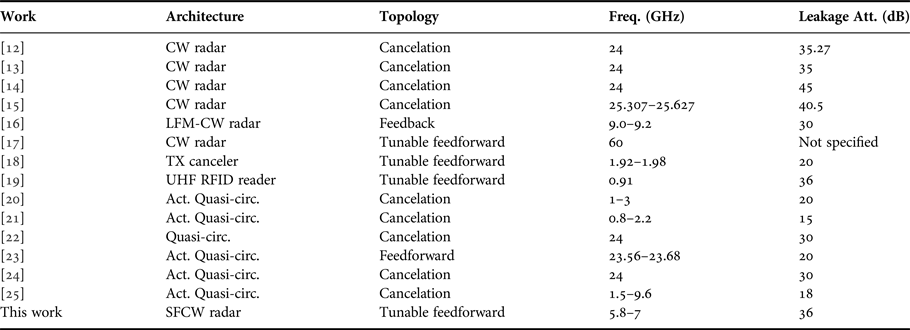
Table 2 summarizes the system's characteristics and performance in comparison with other works reported in the literature. It shows that the proposed architecture achieves a higher leakage attenuation in a bigger relative bandwidth.
Leakage canceler performance comparison.

LFM, linear frequency-modulated.
It should be specified that the objective of this work is to show the use of a monostatic SFCW radar as a potential AAL technology. Therefore, it is out of the scope of this paper comparing optimizers. Moreover, as demonstrated by the authors in [Reference Barmuta35], the efficiency of the DIRECT optimizer showed very fast convergence.
B) Tagless localization
The experimental radar validation has been performed in a real room setting with the radar fixed to the wall at 1 m of height. In the room desks, chairs, shelves, and PCs were present to mimic a real room environment. The IQ baseband signals have been acquired by an oscilloscope and processed offline in Matlab. It should be specified that the oscilloscope can be easily replaced by a dedicated solution based on microcontroller.
A 32 × 52 cm2 metal plate has been located at five different absolute distances, ranging from 1 to 5 m, with a step of 1 m. For each absolute distance, four range profiles have been measured. Since the radar resolution is 15 cm, the target's peaks are expected to be located at the nearest multiples of 15 cm, that is at 1.05, 1.95, 3, 4.05, and 4.95 m. The experimental results show that the target was correctly detected in all 20 measurements. Figure 6 represents the environmental range profiles before and after reflection compensation. The strong peak is caused by the unwanted leakage. Since it is produced by the radar itself, it should be placed at 0 m. The resulting ranging shift of 45 cm is the consequence of the fixed angular phase difference between the received signal and the local copy of the transmitted waveform. This also means that, with this prototype, the real radar detection range is about 5.55 m. As it can be seen by looking at the magnitudes of the range profiles, the use of the feedforward compensation strongly reduces the unwanted leakage. Moreover, the leakage beat frequency is no longer distinguishable. The tones in Fig. 6 after the compensation are mainly due to errors during the calibration process. In fact, the control voltages are provided though digital voltage regulators based on digital-to-analog converters (DACs). Furthermore, the IQ baseband signals have been acquired by an 8-bit ADC present in the oscilloscope. The resolutions of the DACs and the ADC limit the calibration accuracy. The latter depends also on the number of measurements per operating frequency of the optimization algorithm. This sets a trade-off between accuracy and calibration time. Figure 7 show the extracted target's range profile at different distances between the target and the antenna. As explained before, the target has been positioned at the nearest multiples of the radar resolution. It should also be noted that the values of magnitudes of the target's peaks are several orders smaller than the magnitude of the leakage's peak (Fig. 6). This demonstrates that without the use of the leakage canceler network the weak target reflection can never be detected. In fact, as can also be deducted from Fig. 5, by reducing the leakage's reflection, it was possible to reduce the Volts/Div (volts per division) of the oscilloscope to 2.5 mV as opposed to 200 mV set before implementing the feedforward cancelation. In the latter case, the nano Watt target's reflection cannot be detected by the ADC's resolution. Finally, Fig. 8 shows the range profile of a human target at about 2.5 m.
Environmental range profile before and after power reflection compensation. Y-axis normalized to the maximum amplitude measured without the reflection compensation.

Range profile as a function of a distance between the target and antenna. Y-axis normalized to the maximum amplitude measured without the reflection compensation.

Range profile of a person at 2.5 m away from the antennas. Y-axis normalized to the maximum amplitude measured without the reflection compensation.

It should be specified that a monostatic SF(FM)CW radar integrating a frequency-dependent filter/amplifier could not be an alternative solution to the proposed architecture due to the fact that the person's reflection is much weaker than the leakage's reflection. In fact, the target's reflected power at about 5 m is in the order of few pW. This means that the signal should be necessarily amplified before feeding the mixer. Due to the strong leakage's reflection (about 0.2 mW in the radar operating band), the gain of the RF receiver cannot be high otherwise the receiver will be saturated by the leakage, losing therefore also the target's echo information. This means that, after mixing, the target's echo will be so weak to be buried in the noise. This also demonstrates why a frequency-dependent filter/amplifier will not help. The best solution is therefore to strongly reduce the unwanted leakage before the mixer such that it will be possible to increase the RF receiver gain. In this case, the target's signal will be visible at the mixer's output.
IV. CONCLUSIONS
A monostatic CW-based radar sensor with tunable wideband power reflection canceler aiming at long-term indoor contactless health monitoring has been presented and discussed. The designed feedforward power canceler has demonstrated to strongly reduce the unwanted reflection due to poor isolation between transmitter and receiver, as well as antenna mismatch, which represents the largest limitation of wideband monostatic CW-based radar systems. The proposed solution improves the radar detection range allowing having, at the same time, a more compact solution compared with bistatic architectures.
ACKNOWLEDGEMENTS
This work was performed during Ph.D. research of M.M. at KU Leuven. The authors would like to thank Sven Decock of ESAT CDE, KU Leuven, Belgium, as well as Bertold Van den Bergh and Mohammad Rajabi of ESAT-TELEMIC Division, KU Leuven, Belgium. They especially thank FWO Flanders and the Hercules Foundation for supporting this work.
 Marco Mercuri was born in Calabria, Italy in 1985. He received the Bachelor and Master degrees in Electronic Engineering from the Università della Calabria (UNICAL), Italy, in 2006 and 2009, respectively, and the Ph.D. degree in Electronic Engineering from KU Leuven, Belgium, in 2015. He is currently Researcher at Holst Centre/Imec NL, Eindhoven, Netherlands. His research interests include biomedical application of microwave/RF, contactless health monitoring, microwave/RF radar systems, remote radar sensing, and wireless sensors. Dr. Mercuri is a member of the IEEE Microwave Theory and Techniques (IEEE MTT-S). He was the recipient of the 2013 IEEE MTT-S Graduate Fellowship Award, and he obtained the second place both to the 2013 IEEE President's Change the World Competition (PCW) and to the 2013 IEEE MTT-S YouTube/YouKu Video Competition.
 Paweł Barmuta received Ph.D. (with honors) at KU Leuven, Belgium, and Warsaw University of Technology, Poland in 2016. He is currently a Research Associate with KU Leuven and an Assistant with Warsaw University of Technology, where he works towards integration of microwave techniques into biomedical lab-on-chips. From 2008 to 2010, he has been working on firmware and algorithms for automatics in Tele and Radio Research Institute, Poland. From 2008 to 2013, he joined DESY, Germany, as RF designer and R&D manager developing test and measurement systems for particle accelerators. His research interests include non-linear microwave measurements, measurement automation, and calibration techniques. He is recipient of IEEE MTT-S Graduate Fellowship Award in 2015, and author of three best papers (MIKON'12, MIKON'14, and ARFTG'15).
 Ping Jack Soh received the Bachelor and Master degrees in Electrical Engineering (Telecommunication) from Universiti Teknologi Malaysia in 2002 and 2006, respectively, and the Ph.D. degree in Electrical Engineering from KU Leuven, Belgium in 2013. He is currently a Senior Lecturer at the School of Computer and Communication Engineering (SCCE), Universiti Malaysia Perlis (UniMAP). From 2002 to 2004, he was a Test Engineer working on hardware and software test solutions for the manufacturing of All-in-One printers. In 2005, he joined Motorola Solutions Malaysia as an R&D Engineer to characterize and test new two-way radios’ antennas and RF front-ends. From 2006, he joined SCCE-UniMAP as a Lecturer, and went on leave from UniMAP in 2009 to pursue his Ph.D. and research attachment in KU Leuven, Belgium. He was first a Research Assistant (2009–2013), then a Postdoctoral Research Fellow (2013–2014) and is currently an External Research Affiliate in the ESAT-TELEMIC Research Division.
 Paul Leroux was born in Eeklo, Belgium in 1975. He received the M.Sc. degree and Ph.D. degree in Electronic Engineering from the KU Leuven (University of Leuven), Belgium, in 1999 and 2004, respectively. From 1999 to 2004, he was a Teaching and Research Assistant within the MICAS research group of the KU Leuven Department of Electrical Engineering (ESAT). In 2009 he became Assistant Professor at KU Leuven Department of Electrical Engineering (ESAT), where he headed the Electrical Engineering (ESAT) Technology Cluster from November 2011 to July 2016. He was promoted to Associate Professor in 2014. Since August 2016 he is Campus Chair of the KU Leuven Technology Campus Geel. He is also Head of the Advanced Integrated Sensing lab (ADVISE). His current research activities within the ADVISE research group focus on radiation hardened IC design for nuclear fusion, space and high-energy physics applications, circuits for optical communication and instrumentation and micro-electronics for ultra-wideband and microwave sensing systems. His group is part of the CERN CMS collaboration where Prof. Leroux is acting as KU Leuven team leader. Paul Leroux has (co)authored over 110 papers in international journals and conference proceedings. In 2010, he received the SCK-CEN Prof. Roger Van Geen Award from the FWO and FNRS for his highly innovative work on IC design for harsh radiation environments.
 Dominique Schreurs received the M.Sc. degree in Electronic Engineering and the Ph.D. degree from the Katholieke Universiteit Leuven, Leuven, Belgium. She is currently a Full Professor with the Katholieke Universiteit Leuven. She has been a Visiting Scientist with Agilent Technologies, Santa Rosa, CA, USA, ETH Zürich, Zürich, Switzerland, and the National Institute of Standards and Technology, Boulder, CO, USA. Her main research interests concern the (non)linear characterization and modeling of active microwave devices, and (non)linear circuit design for telecommunications and biomedical applications. Dr. Schreurs serves on the AdCom of the MTT Society and also serves as an Editor-in-Chief for the IEEE Transactions on Microwave Theory and Techniques and as the Vice-President on the Executive Committee of the ARFTG organization. She was the General Chair of the 2007 and 2012 Spring ARFTG Conference and the Co-Chair of the European Microwave Conference in 2008. She was an MTT-S Distinguished Microwave Lecturer.