

I. INTRODUCTION
SiC based composites (SiCf/SiCm) are amongst the most promising structural materials for future nuclear applications since the development of third generation SiC fibers. Reference Iveković, Novak, Dražić, Blagoeva and de Vicente1,Reference Snead, Nozawa, Ferraris, Katoh, Shinavski and Sawan2 For instance, first and second generations of SiC fibers did not fulfill the requirements for high temperature and nuclear applications. Their low crystallinity and nonstoichiometry caused these fibers to creep in excess and to ultimately decompose above 1000 °C. Reference Bunsell and Piant3 Under irradiation, these aspects were even more notable. Indeed, fibers with high oxygen content had an inverse behavior as compared to chemical vapor deposited (CVD) SiC. These fibers densified under irradiation whereas the composite CVD-SiC matrix swelled causing the drop of the composite mechanical properties. Reference Snead, Nozawa, Ferraris, Katoh, Shinavski and Sawan2 Third generation SiC fibers, i.e., Hi Nicalon type S (HNS) (Nippon Carbon Co., Japan), Tyranno SA3 (TSA3) (UBE industries, Japan), and Sylramic (Dow Corning), overcome these issues. These fibers are characterized by their CVD-SiC-like behavior due to their high crystallinity, near-stoichiometry, and low oxygen content. Reference Bunsell and Piant3 However, only HNS and TSA3 fibers are considered for nuclear applications due to the boron content of Sylramic fibers. Reference Snead, Nozawa, Ferraris, Katoh, Shinavski and Sawan2,Reference Bunsell and Piant3
SiC fibers play a key role in SiCf/SiCm pseudoductile mechanical behavior. For instance, subcritical crack growth is controlled through fiber creep processes as matrix cracks grow and propagate due to the time-dependent deformation of crack-bridging fibers. Reference Henager, Lewinsohn and Jones4 This lifetime limiting mechanism is of special concern for SiC composites devised for nuclear structural applications as irradiation can enhance creep related mechanisms such as diffusion and lead to time-dependent deformation under loadings where thermal creep is negligible.
When an energetic incident particle elastically interacts with a lattice atom, there is a kinetic energy exchange between them. The energy loss process of a charged particle within a material can be considered as two separated processes. According to the type of interaction, we can distinguish the electronic stopping (S e) and the nuclear stopping (S n) powers, which refer respectively to the inelastic and the elastic processes that causes the gradual energy lose on the particle. In contrast, neutron–nucleus elastic interactions are more straightforward due to their null electric charge. The nuclear interaction regime, when S n > S e, is the regime of important energy deposition of displacement energy and thus the most damaging between the two processes. Reference Was and Averback5
Irradiation enhanced creep (IEC) in SiC has been mostly characterized in a postmortem approach with the bend stress relaxation (BSR) method. This technique was first introduced by Price, Reference Price6 further developed by Morscher and DiCarlo, Reference Morscher and DiCarlo7 and recently used by Katoh et al. Reference Katoh, Snead, Hinoki, Kondo and Kohyama8,Reference Katoh, Snead, Parish and Hinoki9 for the study of irradiation creep in CVD-SiC samples. This method consists of the measurement of the stress relaxation rate by its correlation with a parameter m that ranges from unity for elastic behavior to zero for significant creep behavior. Also, torsion methods have been used by Scholz for Textron SCS-6, a first generation fiber made of CVD-SiC deposited onto a C core filament, Reference Bunsell and Piant3 under deuteron irradiation. Reference Scholz10 Recently, Shankar and Was Reference Shankar and Was11 have adopted an in situ characterization method to determine the effects of proton irradiation in polycrystalline CVD-β-SiC plates.
Each method exhibits advantages and drawbacks. For instance, the simplicity of BSR allows its implementation in testing nuclear reactors and thus neutron irradiation of the samples. However, it presents some difficulties at the time of evaluating the results as the load in the sample does not remain constant during the test. In torsion tests, torque is applied to one end of a long single fiber and the twist angle is measured as a function of time, thus needing a transformation to tensile equivalents to compare the data. Finally, the in situ method adopted by Shankar and Was presents the advantage of independent monitoring of the different parameters involved in IEC. Nevertheless, the experimental facility is devoted to the creep study of large size strips and only under proton irradiation.
The aim of this study is to evaluate the in situ mechanical behavior of SiC fibers under in-pile relevant conditions. With this purpose, TSA3 fibers were tested at different stress loads while ion-irradiated at different fluxes under dominant electronic energy loss regimes using a dedicated tensile creep device.
II. EXPERIMENTAL CONDITIONS
A. In situ tensile test device
The experimental facility used in this work is devoted to in situ axial tensile creep testing of single SiC fibers in a wide range of temperatures and loads and under ion-irradiation. With this purpose, it is devised to be coupled to irradiation lines allowing the access to a broad range of ions, fluxes, and energies.
The device is structured in two independent parts: the core, which is the tensile machine itself, and the vacuum chamber, which allows the core to be coupled to the irradiation lines.
Reference Jankowiak, Grygiel, Monnet, Serruys, Colin, Miro, Gelebart, Gosmain and Costantini12
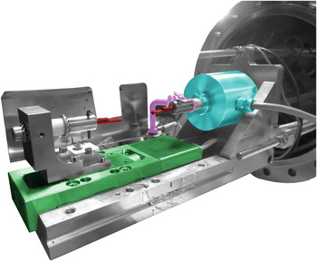
Figure 1 shows the machine core consisting of a displacement table in which the fiber is mounted over two graphite supports. The displacement table imposes the strain and a load membrane cell measures the stress. A Newport MFA CCV6 motorized linear stage (Newport Co., Irvine, CA) permits accurate fiber strain with a maxim applicable axial load of 5 N under secondary vacuums (<10−6 mbar) designed for compactness and mobility needs. It is remarkable that the measured strain takes into account the whole fiber-load cell membrane-clamps system. Thus, it is necessary to consider the system compliance factor and correct the introduced error. The applied load to the fiber is measured by a HBM-U1A force transducer associated with an HBM-AB22A control and display (HBM, Darmstadt, Germany). This sensor is fixed to the core and is attached to the superior graphite support that grips the fiber. The fiber can be heated by Joule effect with a Keithley 2410 High-Voltage Source Meter system Keithley Instruments, Inc., Cleveland, OH). Nevertheless, as ion-irradiation may be a significant heat source besides the Joule heating, temperature monitoring can be performed using an infrared sensor. The temperature of the fibers is then deduced from their spectral emission as the fiber can be assumed as quasi-isothermal with the only heat exchange being due to an irradiative process. The measuring system consists in a parabolic mirror collimator (RCO8FC) coupled to an infrared sensor placed out of the vacuum chamber connected by an optic fiber. The infrared sensor is a Thorlabs PDF10C (Thorlabs, Inc., Newton, NJ) which contains a low-noise photodiode InGaAs delivering a signal between 0 and 10 V as a function of the incident radiation in the 800–1800 nm range. The delivered signal is proportional to
 ${e^{ - {{hc} \over {k{\lambda _2}}}{1 \over T}}}$
, with λ2 = 1800 nm, and to a fourth grade temperature polynomial function. Also, even though the delivered signal saturates at high temperature, it is possible to obtain a signal in the range 400–1200 °C by regulating the distance between the fiber and the sensor. Finally, to regulate the fiber temperature, a control interface has been designed in a LABVIEW environment. The temperature regulator can compensate the heat contribution of the ion flux by decreasing the given electric intensity thus keeping the fiber at the target temperature. However, for the irradiation conditions of this study, flux variations resulted in temperature variations lower than the sensitivity of the temperature control system.
Core of the tensile test machine. In green the displacement table, in blue the force transducer, in purple the heat source connector, and in red the graphite grips.

B. Materials
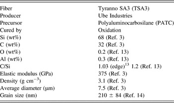
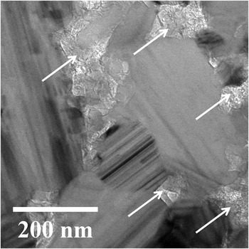
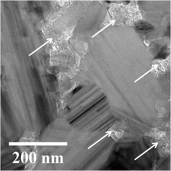
Table I gathers the main properties of TSA3 fibers. These fibers were used for the in situ tensile tests since their diameter is smaller than the projected range of the selected ion in SiC. Thin foils for TEM observation were elaborated using a Helios Nanolab 650 (FEI, Hillsboro, OR) equipped with an electronic beam and a Ga ionic beam. The transmission electron microscope (TEM) observation was conducted in a conventional CM20 TWIN-FEI (Philips, Amsterdam, Netherlands) operated at 200 kV equipped with a LaB6 crystal as an electron source. Figure 2 shows the microstructure of an as-received TSA3 fiber. As it can be observed, these fibers are composed of faulted 3C-SiC grains and free C located in the grain boundaries and triple points. Reference Bunsell and Piant3 Direct measurements on TEM images yield a grain size of 210 ± 84 nm (n = 37). Reference Huguet-Garcia, Jankowiak, Miro, Gosset, Serruys and Costantini14
Tyranno SA3 main characteristics.

As-received microstructure of Tyranno SA3 SiC fiber. White arrows indicate the presence of free intergranular carbon. Intergranular stripped patterns indicate the presence of stacking faults.
C. Sample mounting
TSA3 fibers were selected according to their cylindricity to avoid stress hot spots due to possible diameter variations along the 25 mm sample fiber. To consider the fiber as suitable for the test, the measured diameter dispersion for the same fiber must be lower than 5% in all its length. The diameter measurements were performed every 3 mm using a Carl Zeiss Gemini 1525 Field Emission Gun Scanning Electron Microscope (Carl Zeiss AG, Oberkochen, Germany).
Once the fibers have been selected, they were fixed to two graphite grips using C-based cement C34 (from UCAR Co., Graftech International Ltd., Parma, OH) and submitted to a 12 h heat treatment at 100 °C. Reference Sauder and Lamon13 The graphite grips are then fixed to the displacement table and the force transducer with two copper pins. After the traction bench is placed, the interface software resets the force transducer and allows inputting the parameters of the test.
D. Irradiation conditions
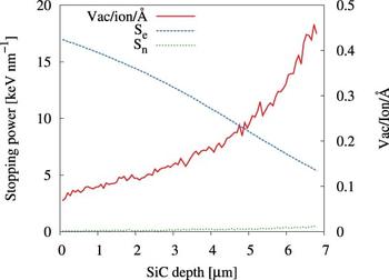
Ion-irradiation is widely used to simulate the radiation damage processes that a material would suffer when exposed to neutron and fission product fluxes. Reference Was and Averback5 In this work, SiC fibers were irradiated with 92 MeV Xe23+ to avoid ion implantation and to induce a homogeneous damage profile. Figure 3 shows the vacancies per ion profile in SiC as calculated with SRIM-2013. Reference Ziegler, Ziegler and Biersack15 Threshold lattice displacement energies (E d) were set to 35 eV for Si and 20 eV for C Reference Devanathan, Weber and Gao16 and the theoretical density to 3.21 g cm−3. Damage calculations were performed with the full cascades mode and the energy losses with the quick damage mode. Reference Zhang, Varga, Ishimaru, Edmondson, Xue, Liu, Moll, Namavar, Hardiman, Shannon and Weber17 As it can be observed, there is a small damage gradient with its maximum at the exit surface of the ion. To compare the radiation effects from different radiation sources, ion fluxes and fluences were converted to both dose rate and dose in displacements per atom (dpa) units using the mean damage value of 0.211 Vac/ion/Å. Also, under this no-implantation condition, the electronic stopping power (S e) is greater than the nuclear stopping power (S n) through all the irradiated thickness being the mean electronic to nuclear stopping power ratio of 125. Finally, Table II summarizes the irradiation conditions for the in situ tensile test.
Ion damage profile in a SiC fiber for 92 MeV Xe23+ calculated with SRIM-2013.

Conditions for the in situ test under 92 MeV Xe23+. Vac/ion/Å is the average damage per ion, S e/S n is the electronic to nuclear stopping powers ratio, and R p is the theoretical projected range as calculated with SRIM-2013.

E. Ion-beam-induced temperature rise estimation
During the experiments, the Joule heating was kept constant despite the increasing ion flux. Therefore, the real temperature of the fiber will be the target temperature plus the ion-beam-induced temperature rise. Under the consideration of a negligible temperature gradient from the fiber core to the surface and a heat exchange only due to radiative processes, Reference Sauder and Lamon13 the ion beam temperature rise will be given by Eq. (1):
 $$\Delta {T_{{\rm{irr}}}}\left( {\dot \varphi } \right) = {\left( {{{{P_{{\rm{irr}}}}\left( {\dot \varphi } \right)} \over {{S_{\rm{r}}}\varepsilon \sigma }} + \mathop {{T_0}}\nolimits^4 } \right)^{{1 \over 4}}} - {T_0}\quad .$$
With
 ${P_{{\rm{irr}}}}\left( {\dot \varphi } \right)$
being the radiated power for a flux
 $\dot \varphi$
, S
r the radiative surface of the fiber, ε = 1 the emissivity of the fiber, σ the Stefan–Boltzmann constant, and T
0 room temperature. Under vacuum conditions, the radiated power is assumed equal to the ion-beam deposited power, which will be given by Eq. (2):
 $${P_{{\rm{dep}}}}\left( {\dot \varphi } \right) = E_{{\rm{ion}}}^{{\rm{tot}}}\dot \varphi {S_{{\rm{rect}}}}\quad .$$
With
 $E_{{\rm{ion}}}^{{\rm{tot}}}$
and S
rect being respectively the total energy deposited in the fiber by a crossing ion and the fiber cross-section perpendicular to the ion beam.
As can be observed in Fig. 4, the ion path length will vary as a function of the entry point of the ion y in the fiber as given by Eq. (3).
 $$L\left( y \right) = 2\sqrt {\mathop {{r_0}}\nolimits^2 - {y^2}} \quad .$$
Schematic representation of the ion path length L as a function of the ion entry point.
 $S_{\rm{e}}^{\rm{in}}$
and
 $S_{\rm{e}}^{\rm{out}}$
stand for the electronic stopping powers of the incident ion at the entry and exit surfaces for an ion path length equal to the fiber diameter given by SRIM-2013.
Reference Ziegler, Ziegler and Biersack15

As the deposited energy by a trespassing ion ΔS
e(L) will depend on the ion path length,
 $E_{{\rm{ion}}}^{{\rm{tot}}}$
will be given by the integral of ΔS
e(L) over the entire fiber diameter, hence expressed as Eq. (4):
 $$E_{{\rm{ion}}}^{{\rm{tot}}} = \int_{ - {r_0}}^{ + {r_0}} {\Delta {S_{\rm{e}}}\left( {L\left( y \right)} \right){\rm{d}}y} \quad .$$
Then, assuming a lineal variation of S e with the ion path length L(y), the energy deposition ΔS e(y) of a 92 MeV Xe23+ ion in the fiber for a given y will be given by Eq. (5):
 $$\Delta {S_{\rm{e}}}\left( {L\left( y \right)} \right) = {{\Delta {S_{\rm{e}}}\left( {y = 0} \right)} \over {2{r_0}}}L\left( y \right) = {{S_{\rm{e}}^{{\rm{in}}} - S_{\rm{e}}^{{\rm{out}}}} \over {{r_0}}}\sqrt {\mathop {{r_0}}\nolimits^2 - {y^2}} \quad .$$
Finally, substituting Eqs. (4) and (5) in Eq. (2) yields a total deposited power given by Eq. (6):
 $${P_{{\rm{dep}}}}\left( {\dot \varphi } \right) = {\pi \over 2}\left( {S_{\rm{e}}^{{\rm{in}}} - S_{\rm{e}}^{{\rm{out}}}} \right){r_0}\dot \varphi L2{r_0} \times {10^8}\left[ {{{\rm{{Å}}} \over {{\rm{cm}}}}} \right]1.6 \times {10^{ - 19}}\left[ {{{\rm{J}} \over {{\rm{eV}}}}} \right]\quad .$$
With L and r
0 being the gauge length and the radius of the fiber in cm and
 $S_{\rm{e}}^{{\rm{in}}} = {{1700\,{\rm{eV}}} \mathord{\left/ {\vphantom {{1700\,{\rm{eV}}} {{{{\rm{ion}}} \mathord{\left/ {\vphantom {{{\rm{ion}}} {\rm{{\AA}}}}} \right. \kern-\nulldelimiterspace} {\rm{{\AA}}}}}}} \right. \kern-\nulldelimiterspace} {{{{\rm{ion}}} \mathord{\left/ {\vphantom {{{\rm{ion}}} {\rm{{\AA}}}}} \right. \kern-\nulldelimiterspace} {\rm{{Å}}}}}}$
and
 $S_{\rm{e}}^{{\rm{out}}} = 500\,{{{\rm{eV}}} \mathord{\left/ {\vphantom {{{\rm{eV}}} {{{{\rm{ion}}} \mathord{\left/ {\vphantom {{{\rm{ion}}} {\rm{{\AA}}}}} \right. \kern-\nulldelimiterspace} {\rm{{\AA}}}}}}} \right. \kern-\nulldelimiterspace} {{{{\rm{ion}}} \mathord{\left/ {\vphantom {{{\rm{ion}}} {\rm{{\AA}}}}} \right. \kern-\nulldelimiterspace} {\rm{{Å}}}}}}$
being the electronic stopping powers of the ion at the entry and exit point of the fiber for a path length equal to the fiber diameter as calculated by SRIM-2013.
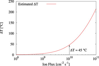
Figure 5 shows the estimated ion-beam temperature rise as a function of the ion flux. As it can be observed, for a flux of 1010 cm−2 s−1 the temperature increment is estimated to be ∼45 °C.
Estimation of the temperature increase of the fiber as a function of the ion flux.

III. RESULTS
A. Thermal creep
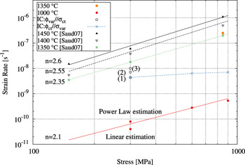
Thermal creep for TSA3 fibers has been determined for relevant mechanical and thermal loadings. Also, a tensile test was performed at 1350 °C and 850 MPa. As it can be seen in Fig. 6, this test confirms the validity of the experimental facility results as the determined strain rate is in agreement with the reported strain rate for TSA3 fibers under the very same conditions. Reference Sauder and Lamon13 Also, creep tests were performed for 300, 600, and 900 MPa at 1000 °C. As shown in Fig. 6, TSA3 fibers are almost insensitive to thermal creep at 1000 °C. For instance, it was not possible to directly determine the strain rate at 300 MPa and 1000 °C from the experimental curve as it was lower than the sensitivity of the experimental facility. Upper and lower bounds for 300 MPa were estimated respectively by fitting the experimentally determined strain rates at 600 and 900 MPa with a linear and power law relationship. Then, the data were fitted with a power law using the upper and lower estimations at 300 MPa and the experimental strain rates at 600 and 900 MPa. As it can be observed in Fig. 6, the power law exponent yields ∼2.1 which is in good agreement with the reported values. Reference Sauder and Lamon13 Finally, thermal creep rates at 300, 600, and 900 MPa yield respectively 6.2 × 10⁻¹¹, 2.8 × 10⁻¹⁰, and 5.3 × 10⁻¹⁰ s−1.
Thermal and irradiation creep of Tyranno SA3 fibers. Numbers in parenthesis refer to the irradiation creep data determined under a constant stress of 300 MPa and 92 MeV Xe23+ fluxes of (1) 109, (2) 5 × 10⁹, and (3) 1010 cm−2 s−1.

B. In situ tensile tests under 92 MeV Xe23+ irradiation
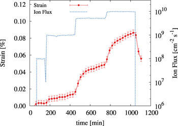
Figure 7 shows the strain curve obtained for the tensile test at 1000 °C and 300 MPa under increasing 92 MeV Xe23+ ion fluxes of 108, 109, 5 × 10⁹, and 1010 cm−2 s−1. As it can be seen, the fiber appears to be unaffected by the ion beam presence for a flux of ∼108 ions cm−2 s−1. Then, for every flux increment, the fiber shows a transient regime followed by a steady state regime. Finally, once the ion beam was stopped, the residual strain of the fiber was ∼0.06%.
Strain curve of TSA3 fiber under 92 MeV Xe23+ irradiation at different ion fluxes at 1000 °C and 300 MPa.

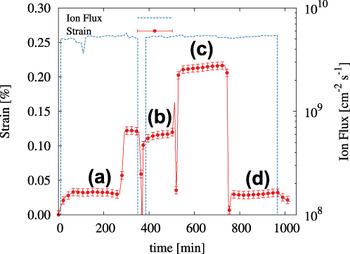
Figure 8 shows the strain curve obtained for the tensile test at 1000 °C and a 92 MeV Xe23+ ion flux of 5 × 109 cm−2 s−1 for tensile loads of (a) 300, (b) 600, (c) 900, and (d) 300 MPa. The fiber shows a transient regime at the beginning of the irradiation. Also, there was an unattended ion beam stop during the experiment. During the stop, the fiber was unloaded and loaded again once the ion beam was reset. As a consequence, the strain rates have been determined from sections (b), (c), and (d) to avoid ion beam fluctuations. Finally, once the ion beam was stopped, the residual strain of the fiber was ∼0.03%.
Strain curve of TSA3 fiber under 92 MeV Xe23+ irradiation at 5 × 109 cm−2 s−1 at 1000 °C and (a) 300, (b) 600, (c) 900, and (d) 300 MPa.

Under these experimental conditions, the total steady state strain rate
 $\left( {{{\dot \varepsilon }_{{\rm{tot}}}}} \right)$
can be considered as the addition of the steady state IEC
 $\left( {{{\dot \varepsilon }_{{\rm{IEC}}}}} \right)$
and thermal creep
 $\left( {{{\dot \varepsilon }_{{\rm{th}}}}} \right)$
rates. Also, due to the nonimplantation nature of the irradiation, the low doses and the tests temperature, ion-swelling has been neglected. This assumption is further developed in the Discussion section. Finally, the steady state strain rate is given by Eq. (7):
 $${\dot \varepsilon _{{\rm{tot}}}} = {\dot \varepsilon _{{\rm{IEC}}}} + {\dot \varepsilon _{{\rm{th}}}}\quad .$$
The steady state IEC rate equation as a function of the stress and the flux is considered under the form:
 $$\dot \varepsilon _{{\rm{IEC}}} = C\left( {\dot \varphi ,\dot \varphi _{\rm{c}} } \right)B_0 \sigma ^n \left( {\dot \varphi - \dot \varphi _{\rm{c}} } \right)^m ;C\left( {\dot \varphi ,\dot \varphi _{\rm{c}} } \right) = \left\{ {\matrix{ {0,\dot \varphi \lt \dot \varphi _{\rm{c}} } \cr {1,\dot \varphi \ge \dot \varphi _{\rm{c}} } \cr } } \right.\quad ,$$
where B
0 and
 ${\dot \varphi _{\rm{c}}}$
stand for the IEC compliance and the threshold ion flux, respectively. The n and m exponents determine the IEC rate dependence with the applied stress and ion flux, respectively. Therefore, if the temperature and the applied stress are constant, m is given by Eq. (9):
 $$\log \left( {{{\dot \varepsilon }_{{\rm{tot}}}} - {{\dot \varepsilon }_{{\rm{th}}}}} \right) = m\log \left( {\dot \varphi } \right) + K\quad .$$
Following the same reasoning and considering the temperature and the ion flux are constants, n is given by Eq. (10):
 $${\rm{log}}\left( {{{\dot \varepsilon }_{{\rm{tot}}}} - {{\dot \varepsilon }_{{\rm{th}}}}} \right) = n\log \left( \sigma \right) + K\quad .$$
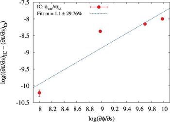
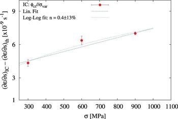
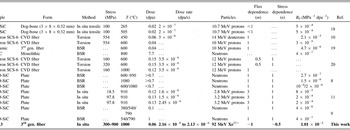
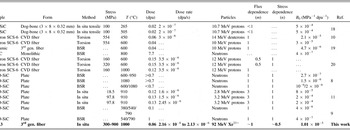
Figures 9 and 10 show the log–log plot of Eqs. (9) and (10). The best fit of the experimental data yields m and n values of 1.1 and 0.4, respectively. Table III gathers literature data for SiC irradiation creep under neutron and ion irradiation. As it can be seen, the dependence of the strain rate with the ion flux is in agreement with the reported m = 1 values Reference Katoh, Snead, Parish and Hinoki9,Reference Scholz10,Reference Scholz and Youngblood19–Reference Katoh, Snead and Golubov21 whereas the determined dependence of the strain rate with the stress load is at variance with the reported n = 1 values. Reference Scholz, Mueller and Lesueur20,Reference Zhu, Mizuno, Kagawa, Cao, Nagano and Kaya22 Also, Table III gathers the B 0 literature values for different experimental configurations. This parameter is defined as the ratio between the strain rate and the stress load and the flux intensity hence takes units of MPa−1 dpa−1. To be able to compare B 0 with the reported values also a linear proportionality with the stress load has been assumed. Figure 10 shows how the experimental data also have a good agreement with the linear fit. Finally, B 0 yields 1.01 × 10⁻⁵ MPa−1 dpa−1.
TSA3 strain rate as a function of 92 MeV Xe23+ ion flux at 1000 °C and 300 MPa.

TSA3 strain rate versus applied stress under 92 MeV Xe23+ irradiation at 1000 °C and 5 × 109 cm−2 s−1.

Irradiation creep compliance for different SiC species and experimental settings.
To model the behavior of the SiC fiber as a function of the ion fluence, the IEC is considered as the addition of a primary (εp) and steady state (εs.s) creep regimes [Eq. (11)]. The former is considered to be under the form of a viscoelastic creep model Reference Katoh, Snead, Parish and Hinoki9 and the latter is given by Eq. (8). Taking into consideration the multistep nature of the test, the total strain for a constant stress load and ion flux is given by Eq. (12):
 $${\varepsilon _{{\rm{IEC}}}} = {\varepsilon _{\rm{p}}} + {\varepsilon _{{\rm{s}}{\rm{.s}}{\rm{.}}}}\quad ,$$
 $${\varepsilon _{{\rm{tot}}}} = \mathop \sum \limits_i \left( {\left( {{p_i} - {p_{i - 1}}} \right){\sigma \over E}\left( {1 - \exp \left( { - {{\varphi - {\varphi _i}} \over {\varphi _{\rm{s}}^i}}} \right)} \right) + {B_0}\sigma \left( {\varphi - {\varphi _{\rm{c}}}} \right)} \right) + {\varepsilon _{{\rm{th}}}}\quad ,$$
where i is the current step of the test, p
i
is the fraction of the elastic strain, σ is the applied stress, E is the elastic modulus, φ is the dose in dpa, and
 $\varphi _{\rm{s}}^i$
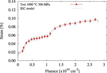
is the saturation dose. The resulting model is mathematically equivalent to the visco-elasto-plastic “four-element model” – a spring–dashpot model consisting in a Voigt model in series with a Maxwell model. As shown in Fig. 11, the model parameters have been fitted to the experimental data as a function of the fluence resulting in a good agreement with the experimental curve. Nevertheless, it should not be considered as a model validation as the same test was used for the model calibration.
Measured fiber strain as a function of the ion fluence versus the MSV-model for the test under 92 MeV Xe23+ at increasing fluxes, 1000 °C and 300 MPa.

IV. DISCUSSION
Tensile creep behavior of TSA3 fibers at high temperatures has been previously characterized revealing a behavior similar to bulk SiC. Reference Bunsell and Piant3,Reference Sauder and Lamon13 In this work, the reported steady state creep rate for relevant experimental conditions is 6.2 × 10⁻¹¹ s−1. This measurement is in agreement with bibliographic data Reference Sauder and Lamon13 and reflects the low sensitivity of these fibers to thermal creep at these stress loads and temperatures.
When stressed under ion-irradiation, TSA3 fibers present time-dependent deformation under conditions where thermal creep is negligible. Reference Jankowiak, Grygiel, Monnet, Serruys, Colin, Miro, Gelebart, Gosmain and Costantini12,Reference Huguet-Garcia, Jankowiak, Miro, Serruys and Costantini23 In the experimental setting, the target temperature was kept constant though the ion beam can be also considered as a supplementary heat source. The ion beam induced temperature rise of the fiber has been estimated as a function of the ion flux being ∼45 °C for the higher ion flux. However, as it can be observed in Fig. 6, such a temperature rise is not sufficient to justify the experimentally determined irradiation strain rates.
It is known that under neutron and ion irradiation SiC swells. For temperatures near the critical amorphization temperature, i.e., ∼150 °C, Reference Huguet-Garcia, Jankowiak, Miro, Gosset, Serruys and Costantini14,Reference Snead, Zinkle, Hay and Osborne24,Reference Weber, Yu, Wang and Hess25 swelling is described as the strain introduced by the irradiation induced defects in the SiC lattice that remain after the postcascade thermally activated recombination. Reference Snead, Katoh and Nozawa26–Reference Zang, Guo, Shen, He, Wang, Pang, Yao and Yang28 For instance, Katoh et al. Reference Katoh, Snead, Parish and Hinoki9 explain the time-dependent deformation at low irradiation temperatures in terms of a coupled swelling–creep mechanism in which the applied stress may introduce anisotropy on the radiation induced swelling. SiC swelling has a decreasing saturation value with temperature until 1000–1200 °C due to the thermal recombination of the point defects. At these temperatures, the reported value under neutron irradiation is in the range of 0.2–0.36% for 1–2 dpa. Reference Snead, Katoh and Connery29 However, above this temperature range, the swelling saturation value begins to increase as the vacancies are sufficiently mobile to accumulate into vacancy clusters which induce void swelling. Reference Snead, Katoh and Nozawa26 Therefore, in this work the swelling impact was minimized on the measured strain because the in situ tensile tests under irradiation were performed at 1000 °C. The measured residual strains obtained after the in situ tensile tests for doses of ∼0.06 dpa yield 0.03–0.06%. As presented in Table II, the projected range of the incident ion is greater than the fiber diameter. Under this condition, the SiC fiber irradiation is under a dominant electronic regime. It has been pointed out that ion irradiation in dominant S e regimes may result in low damage creation as the electronic energy deposition may heal the damage produced by elastic collisions. Reference Zhang, Varga, Ishimaru, Edmondson, Xue, Liu, Moll, Namavar, Hardiman, Shannon and Weber17,Reference Audren, Monnet, Leconte, Portier, Thomé, Levalois, Herlin-Boime and Reynaud30–Reference Sorieul, Kerbiriou, Costantini, Gosmain, Calas and Trautmann33 Given that the swelling at the irradiation temperature is near its minimum and that irradiations with high S e/S n ratios imply low damage creation, the swelling in the in situ test conditions is considered to be negligible.
To ease the comparison, Table III gathers IEC compliances extracted from different experimental configurations and irradiation conditions among the literature. It can be noticed that even though there is a large variability in the literature values, it seems fair to conclude that the testing temperature has a great impact on the fiber mechanical behavior under both ion and neutron irradiation. Also, the technical complexity of the evaluation and comparison of the IEC phenomena in micrometric SiC fibers is remarkable. To reduce the uncertainty that may arise from differences in the testing configuration, both the flux influence and the stress influence on the strain rate of the fibers have been conducted in single tests. The first test was performed at 300 MPa and 1000 °C for increasing ion fluxes and the second test was performed at a constant ion flux of 5 × 109 cm−2 s−1 for increasing stress loads. In addition, both tests were performed at a constant temperature of 1000 °C. From the analysis of the experimental strain curves presented in Sec. III. B, a linear relationship between the flux and the strain rate has been obtained in agreement with Scholz et al. data for Textron SCS-6 SiC based fibers. Reference Scholz10,Reference Scholz, Mueller and Lesueur20 However, the determination of the stress influence yields an almost square root relationship of the strain rate with the applied stress at variance with the reported linear relationship in the literature. Reference Scholz, Mueller and Lesueur20,Reference Zhu, Mizuno, Kagawa, Cao, Nagano and Kaya22 The experimental data analysis yields an IEC compliance of B 0 = 1.01 × 10⁻⁵ MPa−1 dpa−1 under the assumption of a linear dependence with the applied stress. In Table III, the obtained value is ∼25 times higher than the value of 4 × 10⁻⁷ MPa−1 dpa−1 for β-SiC under neutron irradiation at 800 °C. Reference Price6,Reference Katoh, Snead, Parish and Hinoki9 However, it is in the order of magnitude of those IEC compliances obtained in torsion by Scholz, i.e., 3 × 10⁻⁵ MPa−1 dpa−1 (Ref. Reference Scholz10) and in situ by Shankar and Was, Reference Shankar and Was11 i.e., 8 × 10⁻⁵ to 2 × 10⁻⁴ MPa−1 dpa−1, both under proton irradiation. All these experiments have in common that they are irradiated under nonimplantation conditions thus in a dominant electronic energy loss regime.
Even though the phenomenological description of the IEC process is rather simple, the real underlying mechanism responsible of the IEC phenomena remains unclear. It is wise to recall that dislocation motion contribution to SiC plastic deformation is limited to temperatures above 1700 °C thus negligible in our experimental configuration. Reference Sauder and Lamon13 IEC under dominant nuclear stopping range irradiation may be explained by enhanced volume (Nabarro–Herring) or grain boundary (Coble) diffusion creep mechanisms due to the increase of interstitials and vacancies produced by displacement cascades. Reference Mathews and Finnis34 Also, thermal creep in TSA3 fibers has been described in terms of grain boundary sliding due to the intergranular free C compliance. Reference Sauder and Lamon13 Therefore, the irradiation enhanced diffusional processes can lead to an enhanced grain boundary motion by crystallographic slip at C basal planes under the applied stress. For instance, even though experimental data are needed to confirm these hypotheses under relevant conditions, Koyanagi et al. Reference Koyanagi, Shimoda, Kondo, Hinoki, Ozawa and Katoh35 have found a linear correlation between the grain size and the creep strain normalized to the applied stress meaning a contribution of grain boundary sliding to IEC of nanopowder sintered SiC under neutron irradiation for doses between 0.01 and 0.11 dpa. These samples showed a TSA3-like microstructure with an average grain size of 226 nm and free carbon at grain boundaries.
Also, IEC under dominant electronic energy loss irradiations should be considered as the nuclear fuel cladding will be exposed to high energy fission products with electronic stopping powers up to 22 keV nm−1. Reference Was and Averback5 As it can be observed in Fig. 3, the electronic energy loss for 92 MeV Xe23+ in SiC is 17 keV nm−1. Taking into account the differences between the IEC compliances obtained between ion and neutron irradiation, it seems reasonable to presume that energy loss regime plays a role in the mechanical behavior of SiC fibers under irradiation. The high IEC compliances obtained for ion-irradiation under dominant electronic energy regime suggest that inelastic interactions between the incident particle and the lattice atoms are more effective than elastic interactions to accelerate the deformation of the fiber under irradiation. For instance, many authors have described the IEC in terms of stress relaxation in the volume of the thermal spike created by the incident particle. Reference Trinkaus36–Reference Dienst38 Nevertheless, more experimental data for irradiations with different S e/S n ratios are needed to confirm this hypothesis. Finally, as remarked by Scholz, Reference Scholz and Youngblood19 it is wise to comment that high IEC compliance values (∼10−5 MPa−1 dpa−1) may be an important life-time limiting factor for structural nuclear applications.
V. CONCLUSIONS
TSA3 SiC fibers have been successfully in situ mechanically tested under ion irradiation in dominant electronic energy loss regimes. These experiments revealed time-depending deformation of TSA3 fibers at loadings where thermal creep is negligible. For irradiations under dominant electronic energy loss and at 1000 °C, where ion-induced swelling is negligible, IEC presents a two stage creep process consisting in a saturable transient regime that leads to a steady state IEC creep. Irradiation strain rate shows a linear dependence with the ion beam flux and square root dependence with the applied stress. Also, the IEC compliance yields 1.01 × 10⁻⁵ MPa−1 dpa−1 for the experimental conditions of this work. This value is higher than reported values for similar fibers and CVD-SiC under neutron irradiation. This suggests that the ion energy loss regime may play a role in the time-dependent deformation of the fibers under irradiation.
ACKNOWLEDGMENTS
The experiments were performed at IRRSUD beamline of the Grand Accélérateur National d’Ions Lourds (GANIL), Caen, France. The authors would like to thank CIMAP and GANIL staffs for their technical support during the irradiation experiment. This work has been performed thanks to the funding of the EMIR network.