I. INTRODUCTION
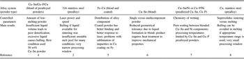
Additive manufacturing (AM) is receiving a lot of interest for advanced part fabrication due to the numerous technological advantages over the conventional “subtractive” manufacturing, such as increased shape complexity (with and without internal topology), reduced waste material, and reduced turnaround time, to name a few. Reference Kruth, Levy, Klocke and Childs1 Among the possible AM technologies, the powder bed approach is one of the most popular methods due to the possible shape complexity and variety of materials used. In this approach, a bed of powder is deposited in sequential layers while an energy source follows a raster path on the surface in the shape of the component being built. A laser-heated powder bed apparatus of this type can be operated in two different modes, namely selective laser melting (SLM) and selective laser sintering (SLS). Reference Kruth, Levy, Klocke and Childs1 The former takes advantage of a high power laser to entirely melt and solidify the powder material under the laser irradiation. The latter, which is normally conducted in the liquid-phase regime, uses the laser to induce surface melting of the powder particle (in prealloyed powders) or a low melting point powder contained in a powder blend. The issue in SLS of prealloyed powders is that the temperature range required for partial surface melting is dictated by the bulk composition (liquidus and solidus temperature), as are the liquid surface tension and viscosity, parameters of importance for the neck development. Since improper control of the latter two factors can trigger coalescence of the liquid in undesirable balling behavior, SLS of prealloyed powder is not an optimal choice. Reference Gu and Shen2 SLS of a powder blend is an alternative but also possess its own hurdle, regarding the wetting and spreading kinetics of the liquid phase, which is typically longer than the molten pool life. In the particular case of Sn wetting Cu, a spreading time on the order of thousands of seconds is needed for the wetting angle to decrease to its steady-state value at temperatures as high as 700 °C. Reference Hasouna, Nogi and Ogino3 A few studies undertaken in SLS for both blended and prealloyed powder systems can be found in the literature, and are summarized in Table I.
Selected works of systems processed by supersolidus AM route.

In addition to these works, an extensive review of different binding types in SLS/SLM has been done, Reference Kruth, Levy, Klocke and Childs1 focusing on the evaluation of factors such as surface tension and viscosity for sintering and melting of prealloyed and blended powders.
SLS also has potential for AM of materials where the total heat input and temperature rise must be kept as low as possible, as well as in forming high-porosity sintered products. This work addresses this situation, where the use of powders coated by a low melting point metal providing the liquid phase for sintering was studied as a way to overcome the spreading kinetic challenges known for powder blends. This type of powder would have the additional advantage of recyclability, when compared with powder blend versions, since there is no risk of segregation of different powder particles by size and density. Only one work was found with respect to SLS of coated powder (in the Fe–Cu system), where better and more uniform bridging between particles is seen as compared with a blended powder Reference Kruth, Van der Schueren, Bonse and Morren5 ; however, no analysis beyond noting the homogeneity of the sample was done.
Sn-coated Cu powder was used as a model system to examine the melting events and compared with a Cu–Sn powder blend with a focus on bonding between particles. Specifically, the solid–liquid interactions and interdiffusion were studied by thermal analysis, microstructural characterization, and analysis of phase formation during AM, and resultant mechanical properties were measured.
II. MATERIALS AND METHODS
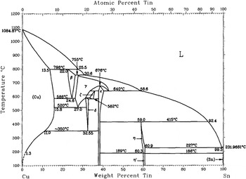
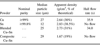
The bronze alloy studied in this project is a 90–10 wt% Cu–Sn binary mixture (with a theoretical density of 8.77 g/cm3); the phase diagram of this system is shown in Fig. 1. Copper and tin powders were obtained from Alfa Aesar. The powder characteristics can be found in Table II. The two different types of feedstocks studied were (1) a Sn-coated Cu powder and (2) a blend of elemental powder used for comparison purposes. The copper-coated powder was processed by immersion tin-plating using a method described in Price. Reference Price10 The plating bath was made up of deionized water, thiourea (from Fisher Scientific), tin (II) chloride dihydrate (from Sigma Aldrich), and hydrochloric acid (from Fisher Scientific) in the ratio of 100 mL : 8 g : 1.2 g : 2 mL, respectively. 1800 mL of this solution was used for plating 100 g of copper powder, giving a ratio of 9:1 of Cu powder to Sn2+ ions, by weight. The bath was heated to 65 °C and magnetically stirred for 120 min to fully dissolve all of the bath components. After this dissolution step, the copper powder to be coated was mixed with 25 mL of methanol to ensure wetting and avoid agglomeration, and then the copper–methanol slurry was added to the stirred coating bath. The powder was left in the bath to react for 120 s, then filtered and rinsed with distilled water, followed by a final rinse in methanol. The powder and filter paper were then dried in ambient conditions for 48 h, followed by 12 h of drying in vacuum. The dried powders were removed from the filter paper and lightly ground with a mortar and pestle to break up any agglomeration formed during drying. The resulting powder alloy is hereafter referred to as the composite alloy. For comparison purposes in terms of AM processing, the elemental powder blend was made by tumbling a mixture of copper and tin powders in a polycarbonate vial, with a ball-to-powder weight ratio of 2:1 and a rotational speed of 150 rpm, for 3 min. This resulting powder alloy is hereafter referred to as the blended alloy.
Cu–Sn phase diagram. Reference Price10

Characteristics of the starting Cu, Sn, and plated powder.

Both powder alloys were characterized with respect to morphology and phase composition. The techniques used to determine these data were scanning electron microscopy (SEM) with a Philips XL30 instrument (Eindhoven, Netherlands) and x-ray diffraction (XRD) with a Philips PW1070 instrument. Characterization of the structure and chemical distribution of the sintered samples was done with both whole samples and polished cross-sections. Both types of samples were examined with SEM, and porosity was also measured using a Skyscan 1172 MicroCT x-ray tomography device (Bruker, Kontich, Belgium) in the sintered samples. In addition, powder and sintered specimens of the alloys were examined using differential scanning calorimetry (DSC) to further understand their structures and compositions using a Mettler-Toledo TGA/DSC 1 instrument (Columbus, OH).
SLS was done using an in-house build facility. A pulsed Nd:YAG laser was used to build the samples using the following parameters: 30 pulses per second, 0.09 kW peak pulse power, 0.2 ms pulse duration, 1 mm spot size, and 1.5 mm/s travel speed. These parameters were chosen since the average energy density was low enough that full melting did not take place (showing that bonding could be achieved via sintering with a tin-rich liquid) and high enough that evidence of liquid formation could be found in both powder types. The specimen size used was 2.5 mm width by 5 mm length by 0.5 mm thickness for XRD and SEM specimens, and 2.5 mm width by 15 mm length by 0.8 mm thickness for mechanical testing. The specimens were fabricated using a hatching distance of 0.1 mm and a layer thickness of 0.2 mm, and in an atmosphere of flowing argon (0.1 L/s). Finally, mechanical testing was performed using a 3-point bending jig with a 9.6 mm span in a Q400 thermomechanical analyzer (TMA; TA Instruments, Woodland, CA).
III. RESULTS AND DISCUSSION
A. Characterization of the starting powders
Table II shows the properties of the powders used in the experiments, specifically particle sizes, measured using light scattering particle size analysis, and apparent densities and powder flow rates, measured as described by ASTM standard B212.
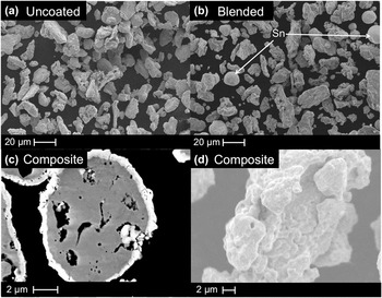
Figure 2 shows the powders used for the experiments. Figure 2(a) is a secondary electron image (SEI) showing the irregular shape of the uncoated powder; Fig. 2(b) shows the blend of the same copper powder with smaller and rounder tin particles. Figure 2(c) is a backscattered electron image (BSEI) of the cross-section of the composite powder where the tin-rich areas are brighter. The coating appears to have a relatively uniform thickness of approximately 0.5–1 μm, as well as essentially complete coverage of the surface. The somewhat porous internal structure of the powder is also evident, and is presumed to be the porosity inherent in a powder manufactured by hydrogen reduction from copper oxide. Reference German11 Figure 2(d) is an SEI of the surface of the tin-coated composite powder. The tin covering the surface has a nodular morphology, which is probably the cause of the low apparent density of the composite powder. Reference German12
SEM micrographs of (a) uncoated Cu powder, (b) blended Cu–Sn powder, (c) cross-section of composite Cu–Sn powder, and (d) surface of composite Cu–Sn powder.

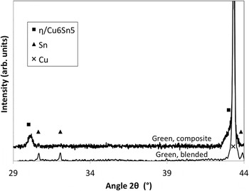
The XRD results obtained from both powders are shown in Fig. 3. The blended powder shows only peaks corresponding to pure tin (JCPDS card 00-004-0673) and pure copper (JCPDS card 00-004-0836). The composite powder contains no apparent elemental tin; instead, the tin-rich outer layer detected is Cu6Sn5 (η phase, JCPDS card 00-045-1488) while the interior of the powder is elemental copper. Intermediate layers of other intermetallics were not detected by XRD, despite the expectation that at least a thin layer of Cu3Sn (ε phase) exists as depicted on the phase diagram. The absence of metallic tin and ε has been seen in other types of chemical tin coatings on copper as well. Reference Fujiwara and Enomoto13 A calculation of the tin content for this powder, based on the assumption of a uniform 0.75 μm layer of Cu6Sn5 (having a density of 8.28 g/cm3) on a 27 μm diameter copper particle, yields 9.95 wt% Sn, thus showing that this type of coating represents the nominal composition.
XRD patterns of composite and blended powders.

B. Evolution of the liquid phase formation during heating for both types of powders
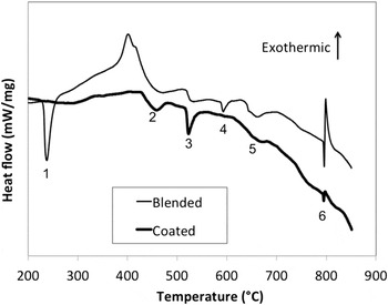
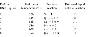
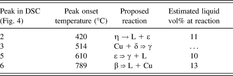
Figure 4 shows DSC data for the blended and composite powders, where both powders were analyzed under apparent density, to mimic as closely as possible the behavior during fabrication. Each sample was heated to 830 °C at a rate of 25 °C/min in nitrogen. The heating rate used was much lower than that expected in SLS, because of the difficulty in obtaining high-quality measurements for very fast heating by this technique. It may be expected, therefore, that the magnitude and temperature of each of the events observed would be different during heating in SLS, particularly those that require substantial diffusion time (for instance, the formation of intermetallic compounds). The endothermic peaks noted for the blended and composite powders are listed in Tables III and IV, respectively, along with the calculated apparent volume of liquid formed based on the integral peak area. This analysis was done by comparing the integrated area (in J/g) to values of enthalpy of fusion from the literature. Reference Zhai, Wang, Geng and Wei14 The results thus obtained are intended as a qualitative comparison of liquid content, rather than a strictly quantitative determination of liquid present for each event.
DSC traces for the blended and composite powders. Labels: 1 = Sn ⇒ L, 2 = η → L + ε, 3 = Cu + δ ⇒ γ, 4 = δ ⇒ γ + ζ, 5 = ε ⇒ γ + L, 6 = β ⇒ L + Cu.

Reactions and apparent liquid volume detected in DSC for blended powder.

Reactions and apparent liquid volume detected in DSC for composite powder.
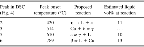
The DSC trace for each powder was interpreted using the well-characterized copper–tin phase diagram. Reference Saunders and Miodownik9,Reference Fürtauer, Li, Cupid and Flandorfer15 The melting of tin in the blended alloy is indicated by the large endothermic peak (peak #1 in Fig. 4) with the onset at 226 °C; this peak is completely absent from the composite powder. The absence of melting in the composite alloy at low temperature is due to rapid interdiffusion of elements Reference Mei, Sunwoo and Morris16 in the coated layer that leads to the formation of the η phase during the coating process. The broad endothermic peak (#2) beginning at 415 °C is present in both powders, and corresponds well to the peritectic melting of the η phase, supporting the idea that the composite powder has formed the η phase through a solid-state transformation. The onset of this peak is also convoluted with the decline of the preceding exotherm (which denotes the formation of η), giving rise to the apparently very large amount of liquid formed (51 vol%); this is likely a much smaller liquid content in reality. The next peak (#3), which is also present in both powders, indicates the eutectoid boundary at 520 °C between δ + Cu and γ. It is followed by a peak (#4) at 589 °C, only present in the blended powder. This peak could result from one of the three events: the eutectoid reaction between the copper solid solution and γ phase, forming the β phase (at 586 °C on the phase diagram – although newer data Reference Fürtauer, Li, Cupid and Flandorfer15 place this reaction at a lower temperature); the eutectoid reaction of ε and δ to make ζ at 582 °C; or the decomposition of δ to make γ and ζ at 603 °C. At 640 °C (peak #5), both powders show the transition from ε to γ with simultaneous melting of γ, and at 680 °C, a small exotherm shows that any remaining ε is converted to γ. The next event (peak #6) occurs at 792 °C, where the only possible reaction, which is much larger in the blended powder, is from β to copper solid solution and liquid. Following this is an exotherm showing dissolution of the liquid phase into copper, which makes estimation of the true liquid content at this point difficult.
In terms of factors affecting liquefaction (and therefore the sintering behavior), the composite powder is most notable for the prolonged absence of liquid during heating. The initial and most tin-rich liquid (92.4 wt%) is formed at 420 °C, a difference of more than 7 wt% in composition and nearly 200 °C compared to the melting of pure tin. At least four of the intermetallic phases (η, ε, δ, and γ) are apparently present at some point during heating. The large speed of diffusion and formation of intermetallics at higher temperatures, in combination with the small length scales inherent in the composite structure, led to a continuously changing composition of both liquid and solids; it must be noted, however, that the much faster heating in SLS probably does not allow enough time for all of these phases to form on heating, even if the small diffusional distances are taken into account.
C. SLS of both types of powders
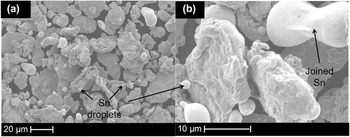
Figures 5(a) and 5(b) show the powder blend after SLS as a baseline result, in which the bonding was so slight that no solid piece could be removed from the powder bed; because of this, no analysis beyond SEM was performed with the blended alloy. In these images, the only change when compared with the starting powder blend is the attachment of small tin droplets to the copper particles and to one another. This indicates tin melting, but without much tin–copper interaction since times on the order of 103 s are typically required for good wetting and subsequent homogenization of this system. Reference Hasouna, Nogi and Ogino3
SEM micrographs of blended powder after SLS: (a) low magnification and (b) high magnification.

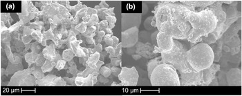
In the coated powder, shown in Figs. 6(a) and 6(b), there appears to be extensive bonding between particles, largely rounded particles and significant necking apparent. There is obvious connectivity between particles, though the extent of melting is not immediately apparent and there is not a complete elimination of pore space between particles.
SEM micrographs of composite powder after SLS: (a) low magnification and (b) high magnification.

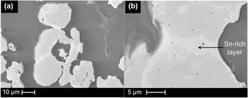
Figures 7(a) and 7(b) show backscattered electron image cross sections of the composite powder after SLS at different magnifications. The laser-sintered powder has regions of clear compositional contrast, with tin-rich bands forming necks and connections between copper-rich regions. This indicates that, while melting and bonding of the tin coating did occur, there was no sufficient time for full diffusional homogenization to take place. In addition, when compared with the unsintered powder an increase in thickness of the tin-rich layer from <1 μm to approximately 3 μm can be seen, which is evidence of redistribution of the liquid toward necks and of dissolution of copper into the liquid, Reference Tuah-Poku, Dollar and Massalski17,Reference Zhou18 which in turn shifts the composition of the tin-rich liquid toward the bulk composition (as indicated by DSC measurements). The non-rounded particle shapes and remnant internal porosity visible in the lower magnification image show that the original copper particles were not melted during sintering and that the bonding between particles is occurring only by liquid-phase sintering through the tin-rich layer. The sintered density of the composite material, measured from x-ray tomography, was 36 ± 2% of the theoretical value. The increase in density (of 17%, compared with the loose powder) is further evidence that sintering processes are effective in creating interparticle bonding and densification.
SEM micrographs of cross-section of composite powder after SLS at (a) low magnification and (b) high magnification.

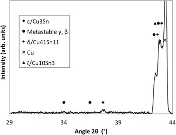
Figure 8 shows the XRD pattern of the composite alloy after SLS. There is no indication of tin or η, while the overlapping peaks near 42° showing some combinations of metastable δ, metastable ζ, and metastable β- and γ-related phases (JCPDS card 04-007-1295 for δ, card 04-010-7872 for ζ, and cards 04-004-6308, 01-071-7875, and 04-010-7872 for the β- and γ-type phases, as well as other Refs. Reference Kennon and Bowles19,Reference Saunders and Miodownik20) are very pronounced. There is also a small peak at 38° indicating that the ε phase (JCPDS card 04-001-2885) is present. The absence of both η and tin shows that the degree of homogenization in this sintered product is closer to equilibrium than in the starting powder. This is likely due to the short distances required for diffusion and the large contact area between the tin-rich and copper phases. The copper peak is still present for the sintered powder, and is not significantly shifted by a change in lattice parameter, showing that there is relatively little tin in solid solution after sintering. This is reasonable, because the extensive formation of a copper solid solution would require the solid-state interdiffusion of tin and copper across distances on the order of tens of micrometers, while the formation of the intermetallic phases can occur directly from the solidification of the tin-rich liquid. This is also verified by the two-layered structure as can be seen in Fig. 7. The XRD results also confirm what is shown by DSC: that the composite SLS specimens, on reheating, contain ε, ζ, γ, and β phases as well as a copper solid solution, and that there is no apparent η or tin phase remaining.
XRD pattern of composite powder after SLS.

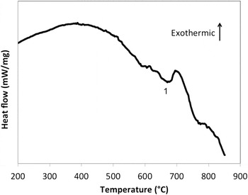
Figure 9 shows the DSC curve for the composite powder after SLS. After reheating the laser-sintered compact of composite powder to 830 °C at 25 °C/min, only two events are noted. The endothermic peak (#1 in Fig. 9) has an onset at 640 °C, where the simultaneous formation (from ε) and melting of the γ phase begin. This is followed closely by an exotherm indicating any remnant ε phase transforming to γ, which then almost immediately begins melting along with any pre-existing γ phase, as indicated by the downward slope beginning at 708 °C. The lack of a distinct melting event near 800 °C is evidence that homogenization has occurred by this point to yield a solid solution of tin in copper.
DSC trace of the composite powder after SLS. Label: 1 = ε ⇒ γ + L.

The apparent absence of the η phase is strong evidence that temperatures higher than 420 °C were reached throughout the sample during laser sintering. Furthermore, the prominence of the ε decomposition peak is an indication that there is a relatively large amount of that phase present after laser sintering (corresponding to 8.2 vol% liquid), which also implies that η has been eliminated.
To evaluate the mechanical properties of the sintered product, the composite powder specimens (having a density of 36 ± 2% of the theoretical value for this alloy, 8.77 g/cm3) were tested in 3-point bending. The flexural strength (based on 3 tests) of these was found to be 6.2 ± 3.7 MPa, with no plastic deformation noted. The relatively low strength might be expected, given the low sintered density of the product as well as the presence of brittle intermetallic phases at particle necks.
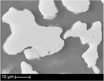
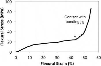
After a homogenization treatment (600 °C for 2 h), to diffuse tin out of the intermetallics and into solid solution and to promote further solid-state sintering, the lattice parameter of the specimen was measured by XRD and found to be 0.3671 ± 0.0003 nm, corresponding to a solid solution of 9.1 ± 0.4 wt% of Sn in Cu, Reference Saunders and Miodownik9 while no phases aside from FCC Cu were found. This indicates a fully homogeneous solid solution, which was verified by SEM as shown in Fig. 10. The 3-point bending strength, calculated with 0.2% offset strain, increased after the homogenization treatment to 14.7 ± 2.2 MPa (with 3 specimens tested), while the density remained essentially unchanged at 39 ± 2% of the theoretical value. More significantly, the samples that had been homogenized were ductile and did not fracture during testing. The bending angle in each case was limited by the geometry of the testing jig to 100°. The substantial ductility of these samples is shown in their flexural stress–strain curves, an example of which is shown in Fig. 11. The inflection point at which the sample reaches maximum bending angle and contacts the jig is also noted.
Backscattered SEM image of cross-section of homogenized SLS specimen.

Flexural stress–strain curve for 3-point bending of homogenized SLS sample.

Fabrication of highly porous copper-based materials for applications in filtration, electrical, and heat-transfer applications has been carried out by a variety of methods Reference Castrodeza and Mapelli21–Reference Parvanian and Panjepour24 ; recently, this has also been attempted by additive manufacturing using electron beam melting. Reference Ramirez, Murr, Li, Tian, Martinez, Martinez, Machado, Gaytan, Medina and Wicker22 The specific yield strengths seen in these materials vary from as low as 0.56 to 15 MPa cm3 g−1, depending on manufacturing method, pore size, and final density. Reference Castrodeza and Mapelli21,Reference Shehata Aly, Almajid, Nakano and Ochiai23 The specific strength achieved with the homogenized samples in the current work (4.3 MPa cm3 g−1) falls in the same range, and as such, shows that the additional versatility and flexibility in design gained by using an additive manufacturing method do not adversely affect the attained properties.
IV. CONCLUSIONS
A copper–tin composite powder was fabricated with the aim of improving bonding in the early stages of melting for SLS or SLM. This composite powder was compared with a blended powder of the same composition. There were a number of findings:
-
(i) The composite powder that was fabricated by immersion plating consisted of a uniform ∼1 μm shell of η (Cu6Sn5) around a copper core, as determined by SEM, DSC, and XRD.
-
(ii) After SLS, there was significant pendular bonding and densification in the composite powder, while there was insufficient interparticle bonding in the blended powder to form a solid component. It could be seen that the bonding was accomplished by thin layers of copper–tin intermetallic phases, identified as ε and metastable β and γ derivatives, while in the blended powder, a lack of homogenization was seen as elemental tin was still found in rounded, poorly-wetting droplets. The peak temperature during SLS can be estimated to be between 420 and 640 °C, based on the composition of the remaining intermetallic phases.
-
(iii) The characteristic most responsible for the better bonding in the composite powder was the excellent distribution of the tin-rich layer on copper. This also allowed rapid diffusion, which was the reason for the disappearance of the most tin-rich phases in the composite powder during SLS.
-
(iv) The mechanical strength of the as-sintered material was nearly tripled by a homogenization treatment, without densification. This treatment also caused the material to be ductile. The properties of this homogenized material were found to be comparable to a number of high-porosity copper-based materials made by other methods.
ACKNOWLEDGMENTS
The authors would like to thank Mr. Rosen Ivanov and Mr. Petr Fiurasek for their assistance in the experiments, and McGill University for providing funding through the McGill Engineering Doctoral Award.