1.0 Introduction
Smart morphing aircraft is generally designed for specialised missions where smart materials and unique structures are often used [Reference Li and Zhao1–Reference Jinsong, Jian and Yanju3]. To advance aerodynamic performance of aircraft, various approaches have been reported, especially using biomimetic, lightweight, adaptive and multifunctional materials and structures [Reference Yousefikoma4–Reference Hajarian, Zakerzadeh and Baghani6]. Meanwhile, induced drag is the main component of flying drag of the aircraft, which accounts for about 40% in cruise phase, and even reaches 50%–70% in takeoff and climbing phase [Reference Guerrero, Maestro and Bottaro7]. Therefore, it is of great significance to reduce the induced drag during the flight of smart morphing aircraft.
The winglet is known to improve the aerodynamic efficiency and reduce the induced drag by diffusing wing-tip vortices on the wing edge [Reference Raj, Shah and Boomadevi8]. The additional functionalities of winglets include yaw control and vertical stabilisation, as well as to improve efficiency [Reference Ostovan, Akpolat and Uzol9]. However, all of the conventional winglets are designed only in the cruising state and fixed in the aircraft wings with the unchanged cant angle. The geometric parameters and layout of the winglets are optimised only for the cruise phase, while variable cant angle winglet can change the lift drag ratio of the wing and improve the aerodynamic performance of the aircraft [Reference Wang, Khodaparast and Friswell10]. It is imperative to design the morphing aircraft winglet benefiting in the whole flying phase including take-off, climbing, cruise, etc. It is expected that the winglet with variable cant angle can change the geometry and parameters in real time, and provides the aircraft with optimal drag reduction effect throughout the whole flight envelope. For example, increasing the cant angle during take-off minimises induced drag and allows the aircraft to take off with less thrust. This can reduce energy consumption and vibration noise. When the aircraft reaches the cruising altitude, the winglet returns to the initial design state to optimise the resistance characteristics of the cruise phase.
The aircraft winglet has been studied for decades [Reference Pecora, Magnifico and Amoroso11,Reference Eguea, Silva and Catalano12]. Most of existing methods of carrying morphing aircraft winglets are used rigid components, with joints, linkages, gears, and motors. Winglets with variable cant angles can even be used as aerodynamic rudder to control aircraft for roll and yaw manoeuvers [Reference Noviello13]. Wang et al. [Reference Wang, Khodaparast and Friswell14] carried out conceptual study of a morphing winglet based on unsymmetrical stiffness. The morphing winglet has to change its cant angle, and its stiffness has to be large enough to carry loads. Bourdin et al. [Reference Bourdin, Gatto and Friswell15] investigated a novel method for the control of morphing aircraft. The concept consists of a pair of winglets with adjustable cant angle, independently actuated and mounted at the tips of a baseline flying wing. Arena et al. [Reference Arena, Concilio and Pecora16] carried out an aero-servo-elastic design of a morphing wing trailing edge system for enhanced cruise performance. Dimino et al. [Reference Dimino, Gallorini and Palmieri17] addressed actuator integration aspects of a winglet shape-changing flight surface capable of adaptively enhancing aircraft aerodynamic performance and reducing critical wing structural loads. Breuker et al. [Reference De Breuker, Abdalla and Gürdal18] designed morphing winglets with the inclusion of nonlinear aeroelastic effects; it has been shown that morphing winglets can improve the performance of fixed winglets significantly for regional airliners. However, the conventional winglet is mainly composed of rigid components, with joints, linkages, gears, and motors, although the aircraft winglet systems can perform tasks with precise and articulated motion [Reference Duan, Wu and Xu19–Reference Hassanalian, Quintana and Abdelkefi26]. There are many disadvantages like heavy weight and requiring cost. Particularly, the complex integrated feedback-based control and driving systems are required to the conventional mechanical winglet.
Smart materials and structures play a significant role in the design of flexible morphing aircraft, without requiring additional mechanical components and complicated control systems [Reference Li, Liu, Wu and Xiang27–Reference Jha and Kudva29]. The smart morphing aircraft winglet has developed by mimicking biological behaviour using smart materials, which can deform flexibly during actuation. Bilgen et al. [Reference Bilgen, Butt and Day30] presented a completely piezoelectric controlled aircraft; a type of piezocomposite actuator was used for changing the camber of all control surfaces on the aircraft. Han et al. [Reference Han and Rodrigue31] investigated the aerodynamic performance of a self-contained morphing winglet for an unmanned aerial vehicle that mimics the wing-tip feathers of gliding birds. Various actuators made of smart materials have been used in the field of the smart aircraft, such as shape memory alloys (SMAs), shape memory polymers (SMPs), piezoelectric zirconate titanate (PZT) and piezoelectric Macro Fiber Composites (MFCs) [Reference Giurgiutiu32–Reference Nguyen and Truong39].
It is emphasised that piezoelectric MFC as an excellent actuator was invented in 1996 by the National Aeronautics and Astronautics Administration (NASA) Langley Research Center. MFCs have been widely used in smart controllers, actuators, and sensors. MFCs provide accurate control and electromechanical signal conversion for intelligent actuator and sensor through its unique electromechanical coupling characteristics.
An innovative smart morphing winglet driven by MFC is proposed, inspired by the bionic ideas of the tip feathers of gliding birds. The smart morphing winglet consists of a power supply, DC-DC converter, MFC bending actuator winglet part and wing part. Intelligent MFC bending actuator is selected as the driving components of the winglet in this paper. By controlling the input voltage, the winglet driven by MFC bending actuator can perform soft and smooth rotational deformation to optimise the cant angle. The aerodynamic coefficients are measured using an open-blowing type wind tunnel testing for different angles of attack under low and high wind speeds. The winglet driven by intelligent MFC bending actuator can be continuously deformed by driving voltage for the different flight states of aircraft. This ensures that the aircraft always maintains the best aerodynamic performance during the whole flight process.
This paper is organised as follows: Section 2 provides the design method and characteristics of smart morphing winglet and MFC bending actuator. Section 3 illustrates the wind tunnel test and aerodynamic experiment of the smart morphing winglet device, and Section 4 is devoted to the conclusion.
2.0 The smart morphing winglet driven by mfc actuator
2.1. Concept
Here, we report on a novel smart morphing winglet actuating by intelligent MFC bending actuator. The smart morphing winglet device consists of the intelligent MFC bending actuator, a hinge, winglet part and wing part. The power supply and DC-DC converter are hidden in the wing part, and the angle between the winglet and the vertical is defined as the cant angle α, as shown in Fig. 1. The intelligent MFC bending actuator as a key component of smart winglet is designed. As a part of the winglet, a hinge shown in Fig. 1 is used, which transfers the deformation to create a smart morphing winglet that exhibits flexible rotational deformation with lightweight system.
A schematic diagram of the smart winglet driven by MFC bending actuator.

This structure of undeformed and deformed smart morphing winglet are shown in Fig. 2(a) and (b). MFC bending actuator is flat with no voltage input. Then the MFC induced by the driving voltage with its electro-mechanical coupling characteristics, which results in the bending deformation of the substrate, enabling the winglet to achieve significant rotating motion with the slippage of the MFC bending actuator along the wing, as shown in Fig. 2(b). The cant angle can be varied depending on the driving of intelligent MFC bending actuator in the winglet. The length of the short handle s and the bending height of the MFC bending actuator y are shown in the Fig. 3(a) and (b), then the change of the cant angle Δα can be obtained by Equation (1).
 \begin{align}\Delta \alpha = \arcsin {y \over s}\end{align}
The rotating performance of the winglet is evaluated to determine the optimal design, considering the response time and the driving force. The advantage of the proposed design is to increase winglet flexibility with less increase in the induced drag force and weight of the aircraft during the various flight conditions. The movement of the actuator can be changed by varying the position and the orientation of the MFCs. Moreover, multi-dimensional motion like spanswise and chordwise bending can be achieved by controlling the arrangement of the MFCs, which can mimic complex biological behaviour.
A schematic diagram of the flexible motion of winglet; (a) unmorphed winglet (b) morphed winglet, where α denotes the cant angle.

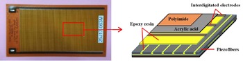
Schematic diagram of MFC used in the winglet structure.

2.2. MFC bending actuator
2.2.1 Experiment of MFC bending actuator driven by DC voltage
Several tests and simulations are carried out to evaluate the bending capability of the MFC bending actuator with various thickness and elastic modulus of the substrate, including response time and bending force tests.
The intelligent MFC bending actuator is fabricated with the following dimensions: a matrix with 100mm length, 36mm width, and 0.2mm thickness, and a M-5628-P1 MFC supported by Harbin Core Tomorrow Science & Technology as shown in Fig. 3. The “P1” of M-5628-P1 MFC indicates that it is an elongating MFC, which utilises the d 33 effect for actuation. Here, the MFC comprises three parts—a piezoelectric ceramic fiber layer, an interdigitated electrode and a polymer matrix. MFCs use interdigitated electrodes to apply a uniform voltage along the length of the piezoelectric fibers, thereby making them contract or extend depending on the voltage potential.
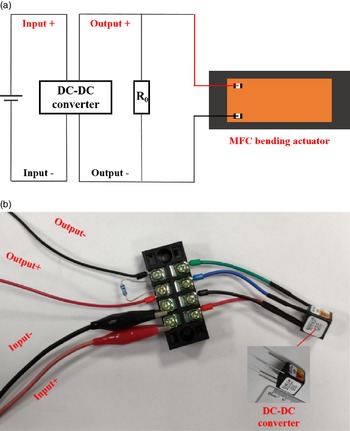
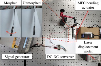
An experiment is proposed to characterise the MFC bending actuator. The schematic diagram of its driving circuit is shown in Fig. 4(a), where R 0 is a resistor used to accelerate the recovery deformation of MFC bending actuator. The DC-DC converter device can transfer the low voltage (0–5V) of power supply to high voltage(0–1,500V) with low weight, small size, and the power only 0.33W, as shown in Fig. 4(b). Low voltage of power supply input in DC-DC converter is converted into high voltage to drive MFC. As shown in Fig. 5, one side of the MFC bending actuator is fixed by the magnetic generator. The end of the substrate is illuminated by a laser displacement meter to show its maximum deflection.
Circuit of the MFC actuating test; (a) diagram of the circuit, (b) the DC-DC converter.

The actuation test of MFC bending actuator.

The signal generator transmits low voltage to the converter. When the driving voltage converted by DC-DC converter is applied, there will be a deflection at the end of the MFC bending actuator, and the deformation will be restored when the voltage is removed. The resistor will accelerate the recovery stroke when the high voltage is removed. The output voltage, end deflection of the MFC bending actuator and time to recovery deformation are different because of the different of resistance.
The input voltage is set to 2.5V. The results are shown in Table 1; with the increase of resistance value, the output voltage first increases and then decreases, and the end deflection and recovery time gradually increase. When the resistance is 20MΩ, the deformation is still 4mm, and it only takes one second to recover its deformation. In this paper, 20MΩ is considered as the optimum resistance which can accelerate the recovery deformation without affecting the driving displacement of the MFC bending actuator in this actuation test.
The relationship of the output voltage, deflection of the MFC bending actuator and time to recovery deformation with of varied resistance value

Figure 6 shows the deformation of the intelligent MFC bending actuator induced by a DC voltage. The driving voltage is continuously applied to the actuator till reaching the maximum deformation. As shown in Fig. 6, the end deflection of the steel sheet varies linearly from 0 to 7.9mm when the input voltage from 0 to 5V, which supplies sufficient motion to actuate the rotation motion of the smart morphing winglet. The bending deflection of the intelligent MFC bending actuator varies smoothly, which is an important aspect of the morphing performance of the winglet.
The deflection of the end of the substrate and the input voltage.

2.2.2. Simulation and optimisation of the MFC bending actuator
The efficiency of the designed smart morphing winglet driven by the MFC actuator needs to be predicted more efficiently by the finite element method. Therefore, an electro-mechanical finite element model is developed to simulate the deformation behaviour of the proposed MFC bending actuator.
MFC is a kind of inhomogeneous composite. It illustrates that the electrodes and piezoelectric fibers play a major actuating role in it, so the effective elastic modules and piezoelectric parameters of MFC are used to simplify the MFC as a homogenous body in the numerical process. The handbook supported by Harbin Core Tomorrow Science & Technology states that the active area of the M-5628-P1 MFC is 56mm in length by 28mm in width. And the thick of the MFC actuator is 0.3mm. The maximum displacement (0° fiber direction) of MFC is 0.108mm under maximum driving voltage of −500–1,500V input on the negative and positive electrodes of MFC, respectively, and the maximum output force is 450N at a driving voltage of 0–1,500V.
The equivalent M-5628-P1 MFC finite element model is established based on the results of the maximum displacement and output force obtained from the product manual. As shown in Fig. 7, the initial piezoelectric constants and elastic modulus of a common piezoelectric material are inputted to obtain the original elongation deformation and the original reaction force. Then comparing the elongation deformation and reaction force data in the manual, the piezoelectric material properties and elastic modulus are continuously adjusted until they match the elongation deformation and reaction force in the product manual. Therefore, the equivalent MFC material properties derived from this process are given in Table 2, the equivalent piezoelectric constant d 33 and elastic modulus are included. In this case, the mechanical and electrical properties of the equivalent MFC finite element model are consistent with the parameters of the product manual.
Effective material parameters of the equivalent M-5628-P1 MFC

Flowchart of FEM implementation procedure of the equivalent MFC material properties.

Numerical simulation of the MFC bending actuator; (a) FEM model, (b) FEM mesh, (c) displacement contour plot (unit: mm).

Deformation of the MFC bending actuator under the finite element method and the test.

This behaviour is simulated using finite element method and verified by the MFC actuation test. Figure 8(a), (b) and (c) shows the model, mesh, and displacement contour plot of the MFC bending actuator, respectively. The deformation of the MFC bending actuator is uniform and the maximum deflection is 7.9mm at the end of the substrate. The comparison between the finite element model and deformation of the MFC bending actuator in the experiment is shown in Fig. 9. It is concluded that the form of deformation is consistent with the result. As shown in Fig. 10, the end deflection of the steel sheet varies linearly from 0 to 7.9mm when the driving voltage varies from 0 to 1,500V, which is consistent with the results from the test of the MFC bending actuator.
The relationship between the deflection of the end of the substrate and the input voltage by simulation and test.

Through the equivalent finite element model of piezoelectric MFC, it can provide reference for the selection of the type of the piezoelectric materials, actuating substrate thickness, elastic modulus, and optimising the actuating effect and actuating force of the MFC bending actuator conveniently. After the effective material parameter of the MFC is obtained, numerical simulations are carried out to derive the cant angle of winglet under different elastic modulus and the thickness of the substrates. The optimised size and materials of the intelligent MFC actuator are demonstrated by a series numerical calculation. Figure 11 shows the relationship of the maximum end-edge deflection and the elastic modules, thickness of the substrate. The result shows that the driving deflection of intelligent MFC bending actuator decreases with the increase of the elastic modulus and the thickness of the substrate. At the same time, the thinner the substrate is, the greater the deformation capacity is, but the ability to resist wind load is also weakened. In order to meet the requirement of motion and load resistance of the winglet driven by intelligent MFC bending actuator in this paper, a 65-Mn steel with elastic modulus 210GPa and the thickness of matrix 0.2mm is used to construct the winglet, and the maximum deflection of the actuator can reach 10.4mm.
Maximum end-edge deflection as a function of the elastic modules and thickness (0.2–0.6mm) of the substrate.

3.0 Apparatus of smart morphing winglet and wind tunnel test
3.1. Initial experiment of the smart morphing winglet
As shown in Fig. 12, the winglet consists of MFC bending actuator, wing part, and winglet part. While wing part with length of 180mm and width of 25mm is fabricated by light wood and plastic film. The winglet part with length of 140mm is made of foam wrapped by carbon fiber, the geometry size of the winglet with symmetrical streamline areofoil is shown in Fig. 13. MFC bending actuator and the hinge are built into the wing part. All connections are made of carbon fiber tubes.
The winglet driven by the intelligent MFC actuator; (a) stereo view, (b) top view, (c) front view, (d) aerofoil view.

Geometry size of the winglet (unit mm).

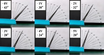
An experiment is proposed to characterise the morphing performance of the winglet driven by intelligent MFC actuator. The signal generator, DC-DC converter, fixture and angle calibration paper are introduced to operate the actuation test of smart morphing winglet. The driving voltage converted from the input voltage of the power supply to high voltage by the DC-DC converter is continuously applied to the smart morphing winglet till reaching the maximum deformation. The morphing performance with an input voltage in the range of 0–5V is analysed using an angle calibration paper. Figure 14 shows the bending angle as a nearly linear relationship of the input voltage. The cant angle of the winglet increases smoothly from 43° to 20° as the input voltage varies from 0 to 5V. The cant angle of the winglet varied smoothly with the driving voltage, which is an important part of the morphing performance. The winglet exhibits highly compliant rotating performance in the actuation test. Figure 15 shows a series of images illustrating the actuation sequence of the smart morphing winglet driven by intelligent MFC actuator with an input voltage of 0–5V. The experimental results show that it is feasible to drive the structure of the aircraft by controlling the intelligent materials with low input voltage.
3.2. Wind tunnel test of the smart morphing winglet
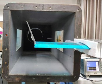
Under different wind speeds, the cant angle of the winglet will change due to the change of wing tip vortex on the wing. Investigation on the properties of the smart morphing winglet driven by intelligent MFC actuator under wind load is essential. The maximum range of the cant angle of the winglet is measured with different wind speeds. The deformation capability of the smart morphing winglet influenced by the aerodynamic force is measured in a wind tunnel. Experiments are carried out in an open-blowing type wind tunnel, as shown in Fig. 16. The dimension of the wind tunnel in the test section is 50cm × 50cm, the wind speeds varied from 4.47 to 8.46m/s by regulating the frequency of fans. The wind blows in the direction of the wing, and the input voltage is provided by a signal generator. The winglet is clamped to the right of the wind tunnel. The range of the varied cant angle can be measured under different wind speeds from 4.47 to 8.46m/s. The relevant parameters utilised in the wind tunnel experiment are listed in Table 3.
Dimensions and parameters of the wind tunnel test

The relationship of the cant angle and the input voltage.

The cant angle of the winglet driven by the different input voltage.

The wind speed v m , winglet cant angle without input voltage and the winglet cant angle at maximum input voltage of 5V is measured by wind tunnel tests. As shown in Table 4, the variation range of the cant angle exhibits slight effects for the low wind speed, i.e. v m <5.0m/s and exhibits varying degrees effect for the high wind speed, i.e. v m >5.0m/s. The control capability of intelligent MFC bending actuator to the smart morphing winglet decreases with the increase of wind speed. At high wind speed, i.e. 8.46m/s, the variation range of the cant angle of the winglet is also 16 degrees, which is still considered to be very useful for improving the aerodynamic performance of the aircraft [Reference Djahid and Sergey40–Reference Guerrero, Sanguineti and Wittkowski42]. Based on these wind tunnel tests, we can conclude that the variable range of cant angle of the winglet brought by the MFC bending actuator can effectively improve the flight efficiency of the aircraft. Hence, it is possible to realise a biomimetic winglet structure using the intelligent MFC bending actuator to realise the wing shape adjustment for different tasks under different wind speeds.
The relationship between wind speed and the range of the cant angle with the input voltage from 0 to 5V

Wind tunnel test setup of smart morphing winglet.

3.3. Aerodynamic performance experiment of the smart morphing winglet
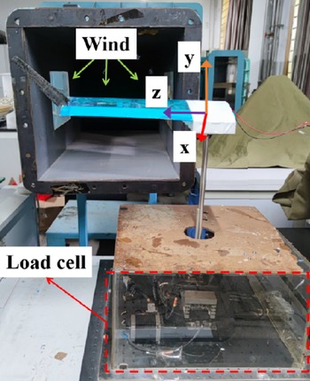
The ability of the morphing winglets to control aerodynamic performance at different angles of attack and different wind speeds was tested. Experiments are carried out in an open-blowing type wind tunnel under low and high wind speeds and the angle-of-attack is varied from 2° to 12° with an increments of 1°. The coordinate system is defined as follows: the positive X-axis is in the streamwise direction, the Y-axis is in the vertical direction, and the Z-axis is in the spanwise direction, with the origin was at the root of the winglet, as shown in Fig. 17. The winglet is attached to the wind tunnel, and a load cell for measuring the lift and drag of the airflow is connected to the root of the winglet through a clamping device. The load cell is placed outside of the wind tunnel test section. The dimensions of the test section of the wind tunnel are 0.6m×0.6m. The wind speeds for the testing are 5.4 and 8.5m/s, respectively, which represent the wind speeds of small UAV in take-off and landing phase and cruise phase, respectively.
A schematic diagram of the setup of the aerodynamic performance experiment.

The coefficients of the lift and drag forces were calculated as follows:
 \begin{align}{C_{L,D}} = {{{F_{L,D}}} \over {0.5\rho U_1^2A}}\end{align}
where L is the lift force, D is the drag force, ρ is the density of air, U
1 is the wind speed, and A is the reference area. In this paper, the reference area A is the projected area of the wing, which is 0.075m2. Figure 18(a) shows the drag coefficients as a function of the angle-of-attack under low wind speed. As the angle-of-attack increases, the drag coefficients become steadily larger for both cases of device input voltage being 0 and 5V. The results show that the winglet has a larger drag coefficient in the case of the device input voltage being 5V. By actuating the morphing winglet, the drag coefficients of the winglet vary by 2.7%–3.7%, which is obtained by comparing the varied value of drag coefficient before and after applying voltage with that before applying voltage, and the maximum difference is 3.7% at
 $\theta$
= 11°. Figure 18(b) shows the lift coefficient as a function of the angle-of-attack under low wind speed, which increases as the angle-of-attack increased. The winglet exhibits a larger lift coefficient in the case of the device input voltage being 5V.
Wind tunnel test results as a function of the angle-of-attack under low wind speed (5.4m/s); (a) drag coefficient (b) lift coefficient (c) lift-to-drag ratio.

Wind tunnel test results as a function of the angle-of-attack under high wind speed (8.5m/s); (a) drag coefficient (b) lift coefficient (c) lift-to-drag ratio.

The lift-to-drag ratios (L/D) calculated from the lift and drag coefficients of the winglet for the different angles of attack under low wind speed are shown in Fig. 18(c). The results show that the winglet with the device input voltage being 5V exhibits better performance. Especially when the angle-of-attack is less than 5°, the difference of the lift-to-drag ratio between the applied voltage of 0 and 5V is obvious. The largest lift-to-drag ratio occurs at
 $\theta=2$
° for both cases. The largest difference between cases of device input voltage being 0 and 5V occurs at
 $\theta$
= 3°, in which the morphed winglet with the device input voltage being 5V shows an L/D approximately 11.9% greater than the case of 0V.
Figure 19(a), (b) and (c) shows drag coefficients, lift coefficient and lift-to-drag ratio as a function of the angle-of-attack under high wind speed, respectively. By actuating the morphing winglet, the drag coefficients of the winglet vary by −2.2% to −6.4% in comparison with the initial geometry, and the maximum difference is 6.4% at
 $\theta$
= 2°. The winglet with device input voltage being 5V exhibits a larger lift coefficient expect
 $\theta$
= 7°. The largest difference is 4.8% between the two cases which occurred at
 $\theta$
= 12°. For lift-to-drag ratio, in which the winglet shows an L/D approximately 6.4% greater than the unmorphed wingtip. Meanwhile, the lift coefficient and drag coefficient increase with the increase of attack angle, but the lift drag ratio decreases with the increase of attack angle.
As shown in Figs 18 and 19, in the wind tunnel tests, the L/D of the winglet is strongly affected by the angle-of-attack. However, the smart morphing winglet with variable cant angle can control the lift drag ratio of aircraft under different attack angles and wind speeds by adjusting the input voltage. The morphing winglet driven by intelligent MFC bending actuator provides potential for enhanced aerodynamic performance based on the cant angle of the winglet.
Based on these wind tunnel tests, we can conclude that the efficiency of the aircraft is able to be enhanced through the use of the smart morphing winglet. As shown in Fig. 20, low flight speed of the aircraft exists in takeoff and landing phase. The small cant angle winglet should be considered for takeoff stages with attack angle of about 5 degrees, while large cant angle winglet should be considered for landing stages with attack angle of about 10 degrees. Meanwhile, high flight speed of the aircraft with attack angle of about 0 degrees exists in cruise phase. In this case, small cant angle winglet should be considered for cruise stages. Therefore, the smart morphing winglet provides the scope to regulate the aerodynamic performance by choosing optimal wing geometry. By selecting the shape of the winglet considering the flight angle and speed, smart morphing winglets mounted on an aircraft show a better performance in comparison to an aircraft with fixed winglets, which further verifies the feasibility of piezoelectric smart material driving intelligent aircraft to complete the real-time adjustment of aerodynamic performance.
Driving behaviour of winglet under different wind speeds and attack angles.

4.0 Conclusion
In this study, a smart morphing winglet with variable cant angle is developed using the intelligent MFC bending actuator. The apparatus is designed to optimise the aerodynamic efficiency for a wide range of flight conditions. Through the integrated winglet design, the reliable morphing of the cant angle could be acquired with smoothly sufficient deformation and control force and rapid response time of the intelligent MFC bending actuator. The cant angle of smart morphing winglet driven by intelligent MFC bending actuator can vary a range of 23° rapidly when the driving voltage of the winglet device increases from 0 to 5V. In high wind speed, the angle MFC actuator can reach 16 degrees, which is still considered to be very pivotal for improving the aerodynamic performance and flexibility of the aircraft. Meanwhile, the lift-drag-ratio of the winglet can be varied by up to 11.9 and 6.4% respectively under the wind speeds of 5.4 and 8.5m/s. The aerodynamic results of the lift-drag-ratio of the low wind speed and high wind speed to different attack angles show that the appropriate cant angle of the winglet can be adjusted by the lift-drag-ratio, attack angle, wind speed and other external environmental factors when the aircraft performs different tasks. Therefore, it is feasible that the adaptive morphing aircraft with smart materials to optimise aerodynamic performance in different flight stages. The future work will better combine the flexibility of piezoelectric smart materials with the compliant deformation of the structure, and a control procedures can be given to complete the control of real-time adjustment from electrical signal to the cant angle of winglet.
Acknowledgements
This work was supported by the National Natural Science Foundation of China (Nos.11772245), the Fundamental Research Funds for the Central Universities in China, and the Natural Science Basic Research Plan in Shaanxi Province of China (Program No. 2018JC-004). In addition, the author Qun Li gratefully acknowledges the support of K.C. Wong Education Foundation.