I. INTRODUCTION
Implantable antenna provides a better means of communication between the human or animal body and the external environment. Implantable devices promise better improvements in patient's care and quality of life. This made researchers show keen interest in the study of implantable antennas. These researches resulted in the innovation of glucose monitoring, pacemaker communication, insulin pumps, endoscopy, retinal prosthesis, and blood pressure monitoring in the field of biomedical engineering [Reference Yazdandoost and Kohno1]. Some patients face difficulty in getting their health condition checked daily at the hospital. This proposed system may be a better replacement for this issue. In such a case, a home care unit can be placed in the patient's house [Reference Ashok Kumar and Shanmuganantham2]. This unit with the accessory networking devices communicates the patient's condition regularly to the concerned person at the hospital.
Medical implant devices had to be magnetically coupled to external equipments. This magnetic coupling required that the device implanted in the patient should be in very close proximity to the external monitoring device, often necessitating body contact for proper operation. In addition to medical implant devices being operated with very slow data rates due to inductive communication, they need a lot of time for the required data transfer. This has been changed by the establishment of medical implant communication services. Therefore, the Medical Implant Communication Service (MICS) overcomes the limitations of medical implant devices. An antenna can be designed in either air or the dielectric of the body [Reference Liu and Yeh3]. If the antenna is designed in air, the antenna's best performance will be achieved when air surrounds the implant. If the implanted antenna is designed in the dielectric of the body, the best performance from the implant will be achieved when the implant is actually inside the body cavity.
Therefore, to design an implanted antenna, it is necessary to place the implant in the medium in which it will be expected to operate. In this paper, an implantable antenna is proposed for Industrial Scientific, and Medical (ISM) band applications. The proposed antenna is found to be compact in size and to have a reasonable return loss of −10 dB to cover the ISM band. Furthermore, the return loss property of the antenna is insensitive to the variation of the electrical properties of the human body [Reference Karacolak, Hood and Topsakal4]. The MICS frequency band has been chosen to reduce the wave attenuation in the complex human environment. As a drawback, the use of the MICS band requires electrically very small antennas [Reference Kim and Rahmat-Samii5, Reference Chien, Cheng, Yang, Jiang and Luo6]. Until now, Microstrip (or) Planer Inverted – F Antenna (PIFA) was proposed for implantable devices, which were covered with dielectric materials in the frequency band of 402–405 MHz [Reference Scarpello7]. Some implanted antennas were analyzed for ISM band applications [Reference Ha, Kwon and Choi8]. We simulate this antenna which can be effectively used at 2.45 GHz ISM band. The use of bigger implantable units restricts the distance of transmission of the signal. This is due to the fact that our body fluids and skin greatly attenuate the signal, and hence it is required to be compact in size. This has the adverse effect on transmission power and the coverage. Such problems can be eluded by the usage of repeater units. The radiation characteristics of tissue implantable antenna mounted over human body is simulated and measured.
The organization of this paper is summarized as follows. In Section II, the geometrical details of the proposed antenna are discussed. This follows Section III, which details the operating principle of the implantable coplanar waveguide (CPW)-fed antenna. This section also provides the proof that the proposed antenna is much suitable for ISM band medical applications with its simulation and measured results. This is followed by conclusion remarks in Section IV.
II. GEOMETRY OF THE PROPOSED ANTENNA
Figure 1 shows the geometry of the proposed antenna. Two narrow slots include an inverted triangle-shaped slot; the insertion of the slot results in the formation of an antenna fed by a CPW-feeding structure. The antenna is composed of a radiating patch fed by a CPW transmission line and a bottom patch to reduce the human body effect on the antenna performance. The implantable CPW-fed double-crossed-type triangular slot antenna for resonant frequency of 2.45 GHz is suitable for ISM band biomedical applications.
Proposed antenna structure.

The proposed antenna design procedure is given in the following steps. (i) The shape of the triangular slot is optimized for wideband impedance matching the CPW feed line included. (ii) An impedance matching transition between the CPW and the input coaxial probe is connected.
The size and the shape of the triangular slot are primary design parameters to determine the bandwidth performance of the antenna. In the initial design stage, the characteristic impedance of the CPW is chosen to be 95 Ω based on the fact that the input impedance of the monopole antenna is about 95 Ω (377/4) [Reference Simons9]. With a 95 Ω CPW feed line in place, the shape of the triangular slot is optimized for the widest possible impedance bandwidth. When the optimum result is obtained, the input impedance of the triangular slot is calculated and the characteristic impedance of the CPW is adjusted for better impedance matching.
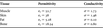
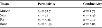
The antenna is printed on a 10 × 12 mm2 alumina ceramic substrate with a thickness of 0.65 mm and relative permittivity of 9.8; the loss tangent is 0.002 and it is implanted into muscle, skin, and fat with permittivity and conductivity as tabulated in Table 1 [10]. Based on the design dimensions shown in Fig. 1, the prototype proposed implanted antenna was designed. For numerical simulation of an implantable antenna, a homogenous human-muscle-equivalent liquid phantom (250 × 250 × 100 mm3) is modeled as depicted in Fig. 2.
Proposed antenna simulation setup model.
Electrical properties of human tissue at 2.45 GHz.
III. RESULTS AND DISCUSSION
The fabricated antenna is shown in Fig. 3. It was fabricated on a biocompatible alumina ceramic substrate of 0.65 mm thickness with dimensions of 10 × 12 × 0.65 mm3. To measure performance, the proposed antenna was immersed in a homogenous liquid phantom, as shown in Fig. 4. An HP 85070E dielectric probe kit and Agilent 8720ES were used together to simultaneously obtain the return loss property of the antenna and the complex permittivity of the liquid. The measured relative permittivity was 52.1 + j12.5 at 2450 MHz, which is an acceptable representation of the electrical properties of a human muscle.
Fabrication of proposed antenna.
Measurement setup for proposed antenna.
Fig. 3 shows that in real-life scenario, the proposed antenna is intended to be implanted into the human body subcutaneously, particularly implanted inside the muscle, fat or skin tissue. Hence the measurement setup, using a human tissue is as follows. The antenna with human tissue is placed at the center of a plastic container of dimensions 250 × 250 × 100 mm3 filled with 1 liter of human body phantom liquid as shown in Fig. 5. This liquid mimics the dielectric characteristics of human muscle, fat, and skin tissue at 2.45 GHz.
Photograph of measurement setup.
The proposed antenna was designed with help of CPW design equations [Reference Simons9]. Figure 6 shows the simulated, measured return loss characteristics of the proposed antenna for human phantom liquid. The measured result agreed well with the simulated one. From the measurement, the 10 dB return loss bandwidth was 180 MHz (8.2%) ranging from 2370 to 2550 MHz. The resonance frequencies and 10 dB return loss bandwidths of the antenna for the various permittivities of the human liquid phantom are depicted in Fig. 5.
Return loss versus frequency.
The simulated and measured results revealed that the return loss property of the proposed antenna showed little changes as the permittivity of the liquid phantom varied from 50 to 80. This is because the resonance frequency of the proposed implanted antenna depends mainly on the alumina ceramic substrate, which is independent of the electrical properties of the surrounding material. This insensitivity is a major advantage in applying the proposed antenna for implantable biomedical devices. Figure 7 shows three-dimensional (3D) current/field distribution. The fields show maximum current distribution in antenna structure.
Current distribution.
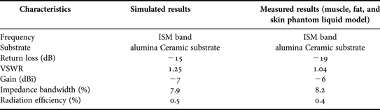
The radiation characteristics of the antenna inside the liquid simulating muscle, fat, and skin tissues are determined in terms of radiation patterns and gain. To simulate, the antenna is directed towards the surface of the gel (muscle, fat, and skin) and along the z-direction. The distance to the surface of the gel is set to be 12 mm in the xy-plane and the antenna is placed in the center of the surface of the human body phantom liquid. The computed radiation patterns in the E-plane and the H-plane are shown in Figs 8 and 9, respectively. The patterns are computed at 2.45 GHz, at a reference distance of 1 m and using an input power of 1 W. The maximum gain is equal to −7 dBi for θ = 0 and φ = 0 and the radiation efficiency is 0.4%. The radiation efficiency is very low because the antenna is not in free space, but embedded into human tissue, simulated as a very lossy tissue medium.
Radiation pattern for E-plane: (a) co polarization, (b) Cross-polarization.
Radiation pattern for H-plane (a) co polarization (b) cross-polarization.
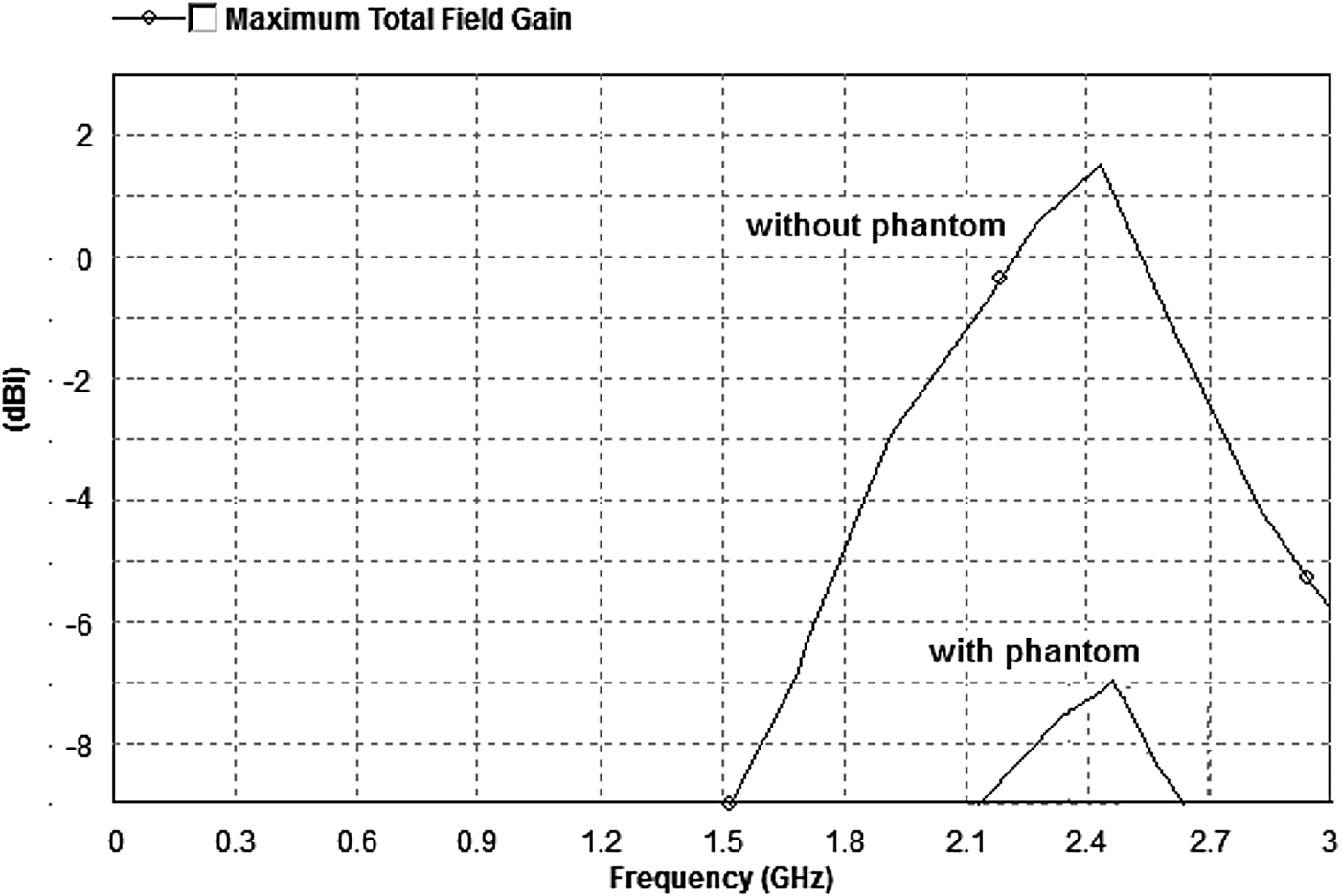
The gain of the antenna was caused by the high dielectric constant of an alumina ceramic substrate. The antenna has a bore sight of 0° and radiates 1 mW. Figure 10 shows the simulated gain of the proposed antenna in free space. The antenna has a maximum gain of −7 dBi at 2.45 GHz. With an antenna so small, made electrically larger via the high permittivity of the implanted tissue, devices such as the input feed can hamper the measurement of gain. With this in mind, the gain for the antenna implanted within the phantom is 1.5 dBi. The gain is varied for the free space and the implantable case.
Simulated proposed antenna gain.
To satisfy the 25 mW EIRP guideline, an 11.8 mW power was delivered to the antenna. The resulting maximum SAR value obtained from the numerical simulation was 1.54 W/kg, which is below the regulated SAR limitation of the American National Standards Institute [11]. Comparisons of simulated and measured results are tabulated in Table 2.
Comparison of simulated and measured results.
IV. CONCLUSION
In this paper, a novel CPW-fed ISM band implantable crossed-type triangular slot antenna proposed for biomedical applications is presented with a compact size of (10 × 12 × 0.65 mm3) and solutions are suggested regarding the design and experimental investigations of the proposed antenna for biomedical telemetry. The design of implantable antennas mainly emphasizes miniaturization and biocompatibility. Conserving energy to extend the life span of the implantable medical device is also significant. ISM band antennas are being designed for these purposes that “wake up” the implantable medical device only when there is a need for information exchange.
A homogenous model is not enough for antenna design, a more sensible model is needed to refine the antenna design and provide perfect results. Owing to better dielectric constant of the alumina ceramic substrates, implantable antenna exhibits miniaturization, lower return loss, good VSWR, better impedance matching, and high gain compared with the other implanted antennas. Therefore, the proposed antenna is the suitable candidate for ISM band frequency of 2.45 GHz in the field of biomedical engineering.
 Srinivasan Ashok Kumar received his B.E. degree in Electronics and Communication Engineering from Anna University, Chennai, India, in 2006 and M.E. degree in Applied Electronics from Thanthai Periyar Government Institute of Technology, Anna University, Chennai, India, in 2009. He has 2 years of teaching experience in Adhiparasakthi Engineering College, Melmaruvathur. He is currently working toward Ph.D. at Department of Electronics Engineering, School of Engineering and Technology, Pondicherry University (Central University), Pondicherry, India. He has authored one book chapter and 15 journal and conference papers. His current research interest includes antenna theory, biomedical telemetry, and implantable antennas.
 Thangavelu Shanmuganantham received his B.E. degree in Electronics and Communication Engineering from University of Madras in the year 1996; M.E. degree in Communication Systems from Madurai Kamaraj University in the year 2000; and Ph.D. (Gold Medal) in the area of Antennas from National Institute of Technology, Tiruchirappalli, India in the year 2010 under the guidance of Dr. S. Raghavan. He has 15 years of teaching experience in various reputed Engineering colleges such as SSN College of Engineering and National Institute of Technology and Science. At present, he is working as an assistant professor in Department of Electronics Engineering, School of Engineering & Technology, Pondicherry University, Pondicherry. His research interest includes Antennas, Microwave/Millimeter-Wave Circuits and Devices, Microwave Integrated Circuits, EMI/EMC, Computational Electromagnetics, MEMS/NEMS, Metamaterials. He has published 75 research papers in various national- and international-level journals and conferences. He has completed one sponsored project, while two projects are in the pipeline. He is a coordinator for MEMS Design Center, NPMASS. His biography was included in Marquis Who is Who in the World, USA in the year 2010. He is a the member of IEEE and life member of IETE, Institution of Engineers, CSI, Society of EMC, ISSS, OSI, ISI, ILA, and ISTE.