I. INTRODUCTION
Electro-brush plating is a technology using electrolysis to implement coatings on metal surface. Compared with electroplating, electro-brush plating has many advantages on treating copper foil, such as simple and portable equipment, nondestructive anode, Reference Morris1 pollution-free, and stabilized character plating bath, efficient plating velocity, and easy realizable automation. Reference Vanek2,Reference Wu, Xu, Zhang, Jing and Liu3 Moreover, electro-brush plating can facilitate a high-performance coating to unification, denseness, and high binding capacity. Reference Tang, Zuo, Tang and Xiong4,Reference Jeong, Jeon, Kim, Kim, Chung and Kim5
Many researchers reported mechanisms and influences of electro-brush plating parameters on coating performances. Brush plating voltage, velocity, and time have significant influences on surface micromorphology, roughness, hardness, and density. Chen and Liu et al. Reference Chen, Ge, Liu, Sun, Zhu, Yan and Qi6,Reference Liu, Wang and Ji7 prepared superhydrophobic nano composite coating on Q345 carbon steel via electro-brush plating, and studied influences of brush voltage, relative velocity, and time on surface micromorphology of Ni-nano composite coating. With the increase of voltage, the grains become finer, and the surface is more similar to the lotus leaf surface. However, with further increase of voltage, a large number of hydrogen and heat is produced, and the cathode polarization effect is more than a range. Coating becomes rough, loose, and the micro/nano hierarchical structure is disappeared. With the increase of velocity between the cathode and anode, reaction time is short that results in little heat, refined grain, and high porosity. Under higher velocity, the reaction time between cathode and anode is very short, and the excessive fast relative velocity makes the ions to deposit unevenly. Li et al. Reference Li, Wang, Gao and Sun8 also found that in the process of preparing SiC reinforced copper composite coatings, nucleation rate of copper increased with the plating velocity, and the porosity increased significantly with increase of current density due to the higher hydrogen concentration in the plating layer. As hydrogen is generated and floats upward, growth of copper grains in horizontal direction is restricted. Thus copper grains tend to grow in the vertical direction and the layers appeared porous at high current densities. Sun et al. Reference Sun, Wang, Hu, Song and Liu9 studied that as the plating voltage increased, crystal nucleus grew and formed quickly, and as the plating time extended, the crystal nucleus grew gradually. Preferentially, growing and tip effect of firstly formed Ni crystal nucleus can lead to the formation of papilla-like structures and pit structures encapsulated with nanoscale Al2O3 particles, and the microhardness of the n-Al2O3/Ni composite coating has remarkably improved. Qian et al. Reference Qian, Tan, Liu, Yu, Xing and Yang10 researched that Cu/Ni multilayer films are first fabricated using brush plating technique. Brush plated multilayer films are highly dense and free from porosity, and the hardness increases gradually with the decreasing sublayer thickness. Zhong et al. Reference Zhong and Clouser11 proposed a method preparing Ni–W alloy coatings without hazardous hexavalent chromium, which is nanocrystalline structure (∼2 nm crystallite size) and demonstrates excellent hardness and wear resistance. A deposit self-repairing mechanism in Pd brush-plating is proposed by Yang et al. Reference Yang, Cai and Chen12 The morphologies of the Pd deposits are made up of spherical nanoclusters and no microcracks. When anode sliding speed is high, H2 bubbles are removed from the anode movement, and in the space of anode sliding, H2 bubbles escape from the deposits actively. As a result, pores were avoided in the Pd deposit by brush-plating.
Currently, many researches and results have focused on brush-plating technological parameters, such as influences of brush-plating voltage, velocity, and time on coating performances. However, there are no related researches on micro-force of anode and cathode contacting in electro-brush plating. Making lucubrate on mechanisms of brush plating, micro-force has great influences on development and application of electro-brush plating technology.
In this study, brush-plating with different micro-force was applied to prepare Zn–Ni alloy coatings on copper foil. The influences of micro-force on surface morphology, microhardness, roughness, and bending performances of coatings were analyzed, and generation and effect mechanisms of electro-brush plating micro-force were revealed.
II. EXPERIMENTAL PROCEDURE
A. Materials and preparation
The substrate was copper foil with dimensions of 0.150 × 20 × 250 mm3. Surface roughness of copper foil was about 70–200 nm. Electro-brush plating was carried out by GSD100A-20V (Shandong Tongda Company LTD, Changyi, China) inverter type power and stainless steel plating pen.
1. Surface pretreatment
Acetone and ethanol were used to clean surface of copper foil. In the electrolytic cleaning procedure, copper foil jointed with the negative pole and electrolytic cleaning solution was used. In the activation procedure, copper foil performed as the positive pole and activation solution was used. Electro-brush plating lasted about 20 s with a relative velocity of 0.4 m/s between anode and cathode.
2. Zn–Ni alloy coating
Solutions were prepared by reagent grade chemicals, which include ZnSO4·7H2O 30 g/L, NiSO4·6H2O 65 g/L, C6H8O7·H2O 90 g/L, CH3COONa 40 g/L, Na2SO4 40 g/L. Electro brush plating lasted about 90 s with a relative velocity between anode and cathode of 0.4 m/s, a voltage of 10 V, pH 2, and ambient temperature (298–303 K). In the process of electro brush plating, the force was added on surfaces with 0.3, 0.6, 1.2, 1.8 N, respectively. Experimental model is shown in Fig. 1. The micro-force was added by 1-Pressing nut (HuaFa Hardware Company, Jinhua, China), and values of micro-force was tested by 2-Pressure sensor (Interlink Electronics Company, Shenzen, China).
Experimental model of electro-brush plating with micro-force, 1-pressing nut, 2-pressure sensor, 3-copper foil, 4-flat type brush plating pen, 5-drive roller, 6-support.

B. Characterization methods
Cross-section coatings were cut out by Zeiss Auriga field emission Focused Ion Beam (Zeiss Company, Oberkochen, Germany). Surface and cross-sectional micromorphologies were observed by Zeiss Auriga field emission scanning electron microscope (Zeiss Company, Oberkochen, Germany).
Surface roughness of coatings was tested by a Dektak XT stylus profilometer (Bruker, Chicago, Illinois) with testing 1000 μm for 30 s and a load of 3.00 mg.
Surface phases of coatings samples (15 × 10 mm2) were measured by TTRIII x-ray diffraction.
Microhardness of coatings was assessed by a calibrated indenter HXD-100T (SHUNHUA Instrument Equipment Co. Ltd., Shenzhen, China), with a load of 100 g. Microhardness values reported here represent an average of eight different values taken in different locations of the specimens.
According to metallic materials bend test GB/T 232-2010/ISO 7438:2005, the dimension of samples (Zn–Ni alloy coatings) is 5 × 100 mm2. The angle of bank, bending angle, bending times, and testing rate are 0.38 mm, 90°, 80 times, 60 times per min, respectively.
III. RESULTS AND DISCUSSION
A. Influences of electro-brush plating micro-force on coatings performances
1. Surface micromorphology of electro-brush plating Zn–Ni alloy coatings
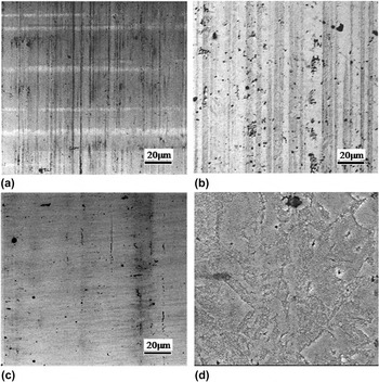
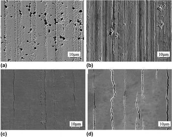
Figures 2(a)–2(d) shows surface micromorphology of electro-brush plating Zn–Ni alloy coatings with 0.3, 0.6, 1.2, and 1.8 N, respectively. With the increase of brush-plating micro-force, surface defects of coatings are reduced and the coatings become uniform. Compared with Zn–Ni alloy coating shown in Fig. 2(a), brush plating Zn–Ni alloy coating applying 1.2 N micro-force shown in Fig. 2(c) was more dense and smooth, and fewer defects. The surface coverage was completed, and rolling traces of rolled copper foil were merely invisible. However, with further increase of brush plating micro-force, which lead to strengthening pressure on coating surface, coating surface becomes coarse and pot holes, as shown in Fig. 2(d).
Surface micromorphology of electro-brush plating Zn–Ni alloy coatings, (a) brush plating 90 s with 0.3 N, (b) brush plating 90 s with 0.6 N, (c) brush plating 90 s with 1.2 N, (d) brush plating 90 s with 1.8 N.

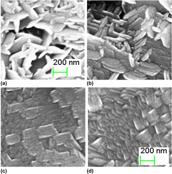
Figures 3(a)–3(d) shows the magnified topo-surface micromorphology of brush plating Zn–Ni alloy coatings in Figs. 2(a)–2(d). Grains size of Zn–Ni alloy coatings was small, and lamellar fine and closely arranged. With the increase of brush-plating micro-force, microstructures of Zn–Ni alloy coatings are refined and homogeneous. Size of grains is obviously minimized by initial width 50 nm and length 300 nm [Fig. 3(a)] to width 30 nm and length 200 nm [Fig. 3(d)], while grains become manifest growth directionality and increased density. Consequently, increased brush-plating micro-force can accelerate crystal nucleation, restrain grains growth, and refine grains.
Surface micromorphology of electro-brush plating Zn–Ni alloy coatings, (a) brush plating 90 s with 0.3 N, (b) brush plating 90 s with 0.6 N, (c) brush plating 90 s with 1.2 N, (d) brush plating 90 s with 1.8 N.

It is shown in Fig. 3(d) that coating was piled up layer upon layer. Based on electro-brush plating feature of interrupted crystalline, grains inner coatings evenly dispersed and the size of that is equivalent. Hence, lamellar and closed microstructure comprised of small size grain is hard to cover the first deposition grain size. Currently, many researches have focused on adding nanoparticles in electro-brush plating solutions to refine grains and improve the strength and plasticity of coatings. However, employing common plating (electro or electro-brush) solutions without additions are difficult to refine grains of a coating surface. In this study, applying common plating solutions with brush-plating micro-force can obtain single-direction nanoscale grains. It is beneficial for improving performances of coatings. Besides above, compared with plating solutions adding nanoparticles, common plating solutions can reduce production cost and simplify dispersion procedure of nanoparticles in solutions. The performance of coating with nanoscale grains has an advantage over that of an ordinary one considerably. Due to the high specific surface area of nanoparticles, which means high surface activity, it is easy to affect fatigue character of coatings. The reason of high mechanical property is that unsaturated chemical bond of nanoparticles surface could combine with metal atoms and form chemical bond, Reference Tu, Xu, Dong and Wang13 which is widely used in composite coatings. Subramanian et al. and Jiang et al. Reference Subramanian, Mohan, Jayakrishnan and Jayachandran14,Reference Jiang, Xu, Dong, Yi and Ding15 both found that applying electro-brush plating was more easier to obtain coatings with high performances of corrosion resistance, homogeneity, density, and nano composite coatings had advantages over that improving coatings performances and hindering cracks nucleation and propagation.
Brush-plating process has influences on growth and arrangement of crystals. Relative motion between plating pen (anode) and copper substrate (cathode) has the effect of driving and pressing on crystals, which are promoted to arrange and fill. The larger micro-force, corresponding to refined, ordered, and dense grains, results in partial broken and be easy to pit corrosion. Hence, influences of micro-force on surface micromorphology, roughness, and corrosion resistance are consistent.
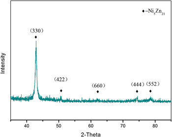
X-ray diffraction (XRD) pattern of brush plating Zn–Ni alloy coating is shown in Fig. 4. Phase Ni5Zn21, which is the main component of phase γ, was analyzed by software and classic equation. Equation (1) is Scherrer equation for calculating particle size. 2θ was 43.38°, which referred to (3 3 0) crystal face. Full width at half maximum (FWHM) was 0.299°, transferred to radiation was 0.0052 (β). Cu target Kα radiation was used, while Kα (1.5431 Å) radiation was composed of
 ${{\rm{K}}_{{\alpha _1}}}$
(1.5406 Å) and
 ${{\rm{K}}_{{\alpha _2}}}$
(1.5443 Å) in ratio 0.5. Accordingly, crystal size D is 28.66 nm, which is in coincidence with actual size in Fig. 3(d).
 $$D = {{0.9\lambda } \over {\beta \cos \theta }}$$
D: crystal dimension, λ: x-ray wave length, 2θ: Ni5Zn21 (3 3 0) radian of diffraction angle, β: full width at half maximum.
XRD pattern of brush plating Zn–Ni alloy coating.

2. Surface microhardness of brush plating Zn–Ni alloy coatings
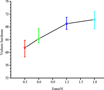
Surface microhardness with different brush plating micro-hardness is shown in Fig. 5. With the increase of electro-brush plating micro-force, surface microhardness of Zn–Ni alloy coatings is increased. However, tendency of the amplification slows down, which means that electro-brush plating micro-force has obvious influence on increased microhardness when the force is small, and when the force is large, the influence is inconspicuous. With the increase of electro-brush plating micro-force, the refined grains and sequential arrangement results in decreased porosity and increased density, which lead to enlarged microhardness. When the micro-force is small, it is not obvious that plating pen drives on grains of coatings. Due to random growth of grains, coating surface has not been covered and filled completely. When the micro-force is large, the obvious effect of plating pen drive and sequential arrangement of grains promoted complete coverage and fill. However, the effect of micro-force is not conspicuous any more, while coating surface has been well covered and homogeneity. Consequently, the curve in Fig. 5 showed a slower increasing tendency.
Surface microhardness with different brush plating microhardness.

3. Surface roughness of brush plating Zn–Ni alloy coatings
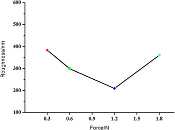
Surface roughness with different brush plating micro-force has been shown in Fig. 6. When the micro-force are 0.3, 0.6, 1.2, and 1.8 N, average surface roughness values of Zn–Ni alloy coatings were 383.98, 299.74, 210.00, and 361.52 nm, respectively. With the increase of electro-brush plating micro-force, surface roughness of coatings is increased firstly and then reduced, which is coincidence with surface micromorphology in Fig. 2. The reason is that coating surfaces are dense and smooth with large electro-brush plating micro-force, and surface roughness is reduced. While coating surfaces have crushed zone and pits with larger force, surface roughness has an abnormal increase.
Surface roughness with different brush plating micro-force.

4. Bending performances of brush plating Zn–Ni alloy coatings
Bending performances and bonding strength with copper foil of Zn–Ni alloy coatings with different micro-force were obtained by bending test. Surface micromorphologies of electro-brush plating Zn–Ni alloy coatings post bending test are shown in Figs. 7(a)–7(d). With the increase of electro-brush plating micro-force, cracks of coatings were increased firstly and then reduced. Surface micromorphologies of post-bending Zn–Ni alloy coatings prepared with 0.3, 0.6, 1.2, and 1.8 N are shown in Figs. 7(a)–7(d), respectively. Many holes and obvious cracks are revealed in Fig. 7(a), which has priority to generate on striped rolling traces and loose place. However, striped undulations, tiny cracks, and partial break were observed on close surface of Zn–Ni alloy coating in Fig. 7(b). The coating surface shown in Fig. 7(c) was smooth and dense, and cracks were far less than Fig. 7(b). However, width, depth, and quantity of cracks observed in Fig. 7(d) were clearly more than Fig. 7(c).
Surface micromorphology of electro-brush plating Zn–Ni alloy coatings post bending test, (a) brush plating 90 s with 0.3 N, (b) brush plating 90 s with 0.6 N, (c) brush plating 90 s with 1.2 N, (d) brush plating 90 s with 1.8 N.

Electro-brush plating with different micro-force have an effect on bending performance and bonding strength of coatings. The coating becomes smooth and dense because of micro-force, while internal stress existed in coatings. The research revealed that cracks are easily generated with stress concentration increased. Reference Dehm, Medres, Shepeleva, Scheu, Bamberger, Mordike, Mordike, Ryk, Halperin and Etsion16 With the increase of brush plating micro-force, the internal stress is increased. However, the coating is smooth, dense, and has bending resistance and high bonding strength when the micro-force is 1.2 N.
B. Mechanisms of electro-brush plating micro-force on coatings
Stamping, rolling, and stretching can make plastic deformation on post-take shape work pieces, that means processes of shaping and plastic deformation conduct successively. However, electro-brush plating is very different from that. In the process of electro-brush plating, ions reduction on the substrate surface and micro-plastic deformation with micro-force conduct simultaneously.
Compared with electroplating, electro-brush plating has relative motion and contact force between anode and cathode, which is reinforce treatment on coating surface. In the process of electro-brush plating, growth orientation of grains turns deflection, which is accordance with brush plating direction. Grains become tenuous and dense, while dislocation and grain boundary increase along with brush plating direction. Based on multi-drive and press, the grains size are small and active atoms on coating surface increased. Active atoms promote passivation film generating on coating surface. Active atoms easily adhere to oxygen to generate a thin oxidation film, which can be used to improve corrosion resistance and intensity of coating. With the variation of coating inner structure, mechanical properties of reinforced coating have significant change, work hardening that results in increased hardness and abrasive resistance.
1. Cross-sectional micromorphology of brush plating Zn–Ni alloy coatings
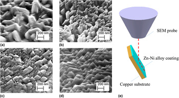
Cross-sectional micromorphology of electro-brush plating Zn–Ni alloy coatings are shown in Figs. 8(a)–8(d). Shoot style of cross-sectional coating is shown in Fig. 8(e). With the increase of electro-brush plating micro-force, organizational order and density of coatings is increased. Compared with electro-plated spherical particle vertical to substrate, coating brush plated with 0.3 N [shown in Fig. 8(a)] was lamellar without fixed growth orientation and run-off the straight. It is clearly shown in Fig. 8(b) that grains were refined and density was increased. Directivity of grains was mostly vertical or slightly lean. Organizational order and density of grains were higher [Figs. 8(c) and 8(d)] than that of Figs. 8(a) and 8(b), and grains lean along with brush plating direction. Grains were refined and surface evenness was very high.
Cross-sectional micromorphology of brush plating Zn–Ni alloy coatings, (a) brush plating 90 s with 0.3 N, (b) brush plating 90 s with 0.6 N, (c) brush plating 90 s with 1.2 N, (d) brush plating 90 s with 1.8 N, (e) shoot style of cross-sectional coatings.

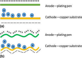
Orientation of grains brush plated with minor micro-force was out of order that is different from grains electro plated. Copper substrate performed as cathode with negative electric charge and plating pen performed as anode with positive electric charge. In the process of electro plating, metal cations in plating solution are attracted on cathode with negative electric charge and reduction on the cathode surface, as shown in Fig. 9(a). Besides, electric field force of cations is vertical to cathode and anode. However, in the process of electro-brush plating, surface sags and crests of cathode and anode could not be ignoring as electroplating. When the plating pen and copper substrate contact, electric field force of cations is vertical to cathode not to anode. The orientation is not regular and unity that is likely to be irreflexive. Hence, brush plated grains with minor micro-force grew tanglesome not upright, as shown in Fig. 9(b).
Schematic diagram of electro-plating field (a) and electro-brush plating field (b).

2. Generation and effect mechanisms of electro-brush plating micro-force
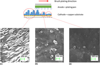
Cross-sectional gradient micromorphology of electro-brush plating Zn–Ni alloy coatings resulted from additional micro-force, which is likely to be plastic deformation. With the motion of brush plating pen, micromorphology of coating was changed. At the front of plating pen, firstborn grains generated (Fig. 10(a)). In the middle of plating pen, grains grow and agglomerate together [Fig. 10(b)]. At the end of plating pen, grains grow lathy and gradient [Fig. 10(c)].
Surface micromorphology of brush plating micro-process, (a) firstborn grains, (b) grains grow and agglomerate, (c) grains grow lathy and gradient.

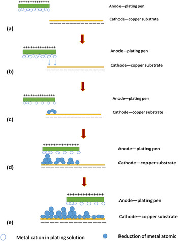
Figure 11 shows schematic of brush plating micro-process. Brush plating pen was covered with mull, which is full of plating solutions. Plating pen performed as anode with positive electric charge, and copper substrate performed as cathode with negative electric charge [Fig. 11(a)]. At the moment of pen contacting with substrate, cathode attracts metal cations to the copper surface [Fig. 11(b)]. Plating pen and copper substrate have relative motion. At the front motion of plating pen, metal cations were reduced and deposited on the copper surface. Because newborn grains have not been driven and pressed, the grains upgrade grew into spherosome followed dynamic law [Fig. 11(c)]. Grains grew and agglomerated together [Fig. 11(d)]. From plating pen moving in a certain part to leaving, grains of this part were lathy and gradient along with direction of plating pen [Fig. 11(e)].
Schematic diagram of brush plating micro-process, (a) before anode contact with cathode, (b) and (c) anode just contact with cathode, (d) and (e) anode depart from cathode.

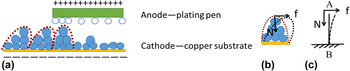
Figure 12 shows principle schematic diagrams of electro-brush plating micro-force. When the plating pen and copper substrate have relative movement, grains cumulated by atoms are treated as a whole and gradient along with direction of plating pen [Fig. 12(a)]. The force analysis of grain is shown in Fig. 12(b). On the top of grain, it is influenced by pressure N of plating pen and friction f of relative motion between plating pen and copper substrate. With resultant action of N and f, grain run-off from the straight and angle between grain and horizontal plane is acute. Model simplification is constraining one side and applying loads on other side, as shown in Fig. 12(c). When force N and f are brought to bear on free end of simple AB, deflection and corner θ are produced. Gradient grains make lower porosity and thinner thickness.
Principle schematic diagrams of electro-brush plating micro-force, (a) micromorphology schematic, (b) and (c) force analysis.

Figure 13 shows principle schematic diagrams of electro-brush plating micro-force on coatings properties. It is clearly revealed in Fig. 13(a) that grains growth is mainly influenced by electric field force when applying minor micro-force. In the process of brush plating, because of surface sags and crests of cathode and anode, electric field force orientation is irreflexive. Hence, brush plated grains grew disordered. In the meanwhile, large grains size resulted in loose coatings, high porosity, low density, large roughness, thin work hardening layer, and minor hardness. However, grains growth is mainly influenced by micro-force when applying major micro-force. Thus, brush plated grains grew ordered and turned gradient. Plastic deformation of grains resulted in grain refinement, low porosity, high density, decreased roughness, thick work hardening layer, and increased hardness, as shown in Fig. 13(b).
Principle schematic diagrams of electro-brush plating micro-force on coatings properties, (a) minor micro-force, (b) major micro-force.

Consequently, surface micromorphology has significant relevance with electro-brush plating micro-force and electric field force, which has great advantages of improving coatings performances. Electro-brush plating, one special technology of electro plating, is anode contacting with cathode. Particularly, on the basis of analysis method of electro plating, mechanics of anode contacting with cathode should be considered, which has great influences on development and application of electro-brush plating technology.
IV. CONCLUSIONS
-
(1) With micro-force increased from 0.3 to 1.2 N, grains were refined and organizational order, density and micro hardness were increased. However, when the force reached to 1.2 N, partial surface damage appeared, which resulted in firstly reduction and then increase of surface roughness. When internal stress was increased bending performance firstly increased and then decreased.
-
(2) It is clearly revealed that smooth and density coating resulted from micro-force. According to the micro-force, plastic deformation and work hardening are generated and performances are improved.
-
(3) It is proposed that electro-brush plating micro-force is one of the important influencing parameters on coatings performances, and it is significant to introduce micro-force in brush plating research.
ACKNOWLEDGMENT
Financial support from National Key Technology Support Program (No. 2011BAE23B02) and Fundamental Research Funds for the Central Universities (No. FRF-TP-10-002B) is gratefully acknowledged.