1. Introduction
One of the challenges in preparing images of the head and neck is the movement of patients’ heads during the image acquisition, which leads to the creation of motion artifacts and reduces image quality. Excessive imaging time of cone beam computed tomography (CBCT) images (from 5 to 40 s) makes patients, especially children, unable to remain still during the imaging [Reference Schulze, Heil, Gross, Bruellmann, Dranischnikow, Schwanecke and Schoemer1]. On the other hand, patients with systemic diseases like Parkinson’s disease should be considered during image preparation, because the patient’s movements lead to the creation of movement artifacts2. The first step in studying the motion artifact in CBCT imaging is to create different movements of the human head, such as rotational, posterior, anterior, and vibratory with a known speed and amount.
To simulate head movements and provide appropriate datasets for studying motion artifacts in the CBCT imaging, a suitable robot is needed to execute the desired movements in a controlled manner. In previous studies, different methods have been used to move the dry skull during the CBCT imaging. Cosimo Nardi et al. placed a dry skull on a long wooden bar and attached the other end to a system to create a variety of motions that transmit motion through a wooden bar to the dry skull [Reference Nardi, Molteni, Lorini, Taliani, Matteuzzi, Mazzoni and Colagrande3, Reference Nardi, Borri, Regini, Calistri, Castellani, Lorini and Colagrande4]. This system has limited head movements. It is also necessary for the operator to be present at the imaging site in order to start and create different movements, and as a result, he/she would be exposed to radiation. In another study, Rubens Spin-Neto et al. used a hexapod robot (Physical Instruments H-820 6-Axis Hexapod) to create various movements [Reference Spin-Neto, Matzen, Schropp, Sørensen, Gotfredsen and Wenzel5]. This universal robot is programmable and is able to create different types of movements with brushless DC motors. In this robot, the power supply and control commands are provided via a connection cable. Also, the presence of metal parts in the imaging area can be problematic in creating artifacts. In another study from the same group, a robot (UR10, Universal Robots, Odense, Denmark) was used to create movement in the human skull. The robot performed the programmed movements by using a wired control panel connected to the robot. The robot was programmed to reproduce four different head movements including anterior–posterior translation, nodding, lateral rotation, and tremor [Reference Spin-Neto, Matzen, Schropp, Sørensen and Wenzel6]. In another study, Arash Dabbaqi et al. examined the effect of patient movement during CBCT imaging [Reference Dabaghi, Sharifi, Pur Mehdi Boroujeni, Bayati and Zaheri7]. To create motion during imaging, they made a device, which could move in the vertical direction (y axis) by 2, 4, and 7 mm in 2 s. This device consists of two main parts: 1. mechanical part, which includes a stepper motor, a shaft, a bush, and connections related to converting rotational motion to linear movement; 2. control panel, which includes circuits and control keys for different operating conditions of the device [Reference Dabaghi, Sharifi, Pur Mehdi Boroujeni, Bayati and Zaheri7, Reference Sharifi, Mohagheghi, Ghasemi, Kavoosi, Mohagheghi, Feyz and Masserat8]. The problem with this system is that it can only move in one direction, and therefore, it is not possible to perform movements such as rotation, vibration, and combination of motions together.
Cable-driven parallel robots (CDPRs) are increasingly applied in different tasks, like rescue systems, rehabilitation, and even 3-dimensional print. A typical CDPR system consists of three parts, including a fixed platform, a mobile platform, and a number of cables, which are used to join the fixed platform to mobile platform. The cable length can be changed through winches actuated by motors installed in the fixed platform [Reference Ennaiem, Chaker, Arévalo, Laribi, Bennour, Mlika, Romdhane and Zeghloul9–Reference Qian, Zi, Shang and Xu11].
In this study, according to the conditions and limitations of the CBCT imaging room, a CDPR was designed and built to simulate different head movements including rotation, tremor, anterior, posterior, and right/left lateral motions. These motions were selected based on clinical evidence, meaning that these movements have been performed repeatedly by patients in the past during CBCT examination [Reference Spin-Neto, Matzen, Schropp, Gotfredsen and Wenzel12, Reference Spin-Neto, Costa, Salgado, Zambrana, Gotfredsen and Wenzel13]. The prototype of the robot has been developed and validated through the experimental tests.
This paper is organized as follows: Section 2 deals with the description of the mechanical and electrical components as well as kinematic model of the robot. In Section 3, the correlation between DC motor speed and pulse width modulation (PWM) duty cycle is explained and description of the robot prototype along with the real tests on CBCT imaging is presented. In Section 4, the capabilities and limitations of the designed robot are discussed. The last section concludes the paper.
2. Materials and methods
In designing a robot, it is necessary to take into account the limitations of the construction and utilizations steps. In this paper, to design a robot that is supposed to emulate and execute possible movements of the patient’s head during the CBCT imaging, the following items should be considered:
-
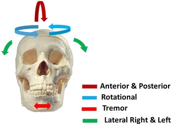
1. According to clinical evidence, the designed robot should be able to perform rotational, vibratory, anterior, posterior, right, and left lateral movements on a dry skull. These movements are shown in Fig. 1.
-
2. The robot dimensions should be designed in such a way that it does not collide with the arm of the radiation tube and the detector of the CBCT imaging system during operation.
-
3. The constructed robot must have the ability to execute and simulate any required head movement.
-
4. To protect the operator from radiation, the robot must be able to be set up and controlled remotely.
-
5. Different parts of the robot should be replaced in a short time so that if a part of the robot is damaged, that part can be easily replaced.
-
6. The designed robot must have sufficient mechanical strength against various movements and be able to withstand the force applied to it during its use.
The robot designed in this research consists of mechanical and electrical components, each of which is discussed below.
A variety of movements created on the dry skull by the designed robot.

2.1. Mechanical components of the robot
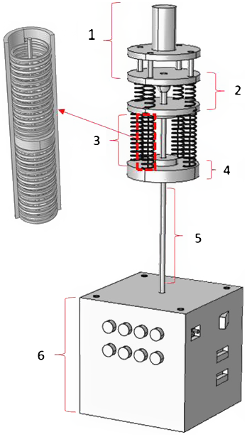
The various mechanical parts of the robot that are designed in the COMSOL software environment are shown in Fig. 2.
Mechanical components of the head movement simulator robot of 3-DoFs along with kinematic architecture and head fixation.

According to Fig. 2, the mechanical components of the robot are divided into six parts, which are described in the following.
Part 1 of Fig. 2 shows the chassis and location of the dry skull. Since this part is close to the skull and in its connection, it is exposed to radiation and therefore, to prevent the metal artifact in the images [Reference Nardi, Borri, Regini, Calistri, Castellani, Lorini and Colagrande4], this part is entirely made of polyamide and Plexiglas. The dry skull mounts on a polyamide cylinder through its circular base cavity.
Part 2 of Fig. 2, with the help of a spherical joint (SQZ8R-RS, Changsha IGS machinery Co., China) embedded in the middle, provides displacement of the dry skull mounted on the chassis. This part also includes four suitable springs (spring constant = 500 N/m) that are installed in the robot to maintain balance and return the skull to its original position. The tension of the skull is provided by four flexible cables that are connected to the lower surface of the skull chassis through the four springs.
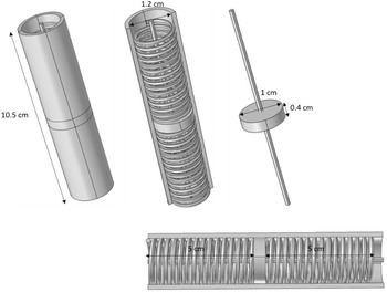
Part 3 of Fig. 2 consists of four cylinders through which the flexible cables pass as shown in Fig. 3. The flexible cables are connected at one end to the pulley mounted on the shaft of DC motor and at the other end to the underside of the skull chassis.
Design of tension system and springs in COMSOL environment. The tension system in two different directions includes a cylinder, two springs separated by a polyamide disc, and a flexible cable (YLI 20210-224 100wt T-12 Silk Thread, Japan).

According to Fig. 3, the two springs in the middle of the cylinder are separated by a solid disk. The cylinder is also fixed from the top and bottom by the top and bottom plates. The flexible cable is firmly attached to the solid disc in the middle, making it possible for the flexible cable to be stretched up and down. The flexible cable is transferred to the upper parts after passing through the hole created in the upper spring axis of the cylinder, and from the lower part of the cylinder, after passing through the appropriate hole, it is connected to the pulley connected to the gearbox shaft until the flexible cable is pulled or released around the pulley during the motor functioning.
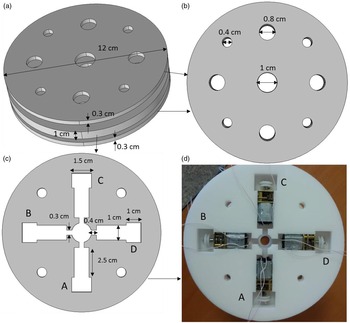
Part 4 of Fig. 2 contains the chassis and location of the four DC motors (12v 30 rpm, Shenzhen Shunchang Motor Co, China). According to Fig. 4, DC motors must be carefully positioned so that the rotational motion is converted to linear displacement with complete accuracy.
Part 4 of Fig. 2 contains the chassis and location of the four DC motors, (a) chassis construction and placement of four DC motors in it, (b) chassis top and bottom plate, (c) location of four DC motors with gearbox and pulley connected to the gearbox shaft, and (d) constructed chassis containing the four DC motors, gearboxes, and pulleys.

As shown in Fig. 4, the power supply wires connected to the motors pass through the built-in slots and connect to the L298 drivers. A circular hole in the middle of the chassis is installed to pass the steel rod to transmit rotational motion.
Part 5 of Fig. 2 shows the steel rod used to transmit rotational motion to the dry skull without delay. This rod is connected from one end to the stepper motor (42BYGH1101-B-265L, Zhongshan Shengyang Motor Co., China) through a suitable bushing and from the other side to the roof of part 3.
Part 6 of Fig. 2 contains the box of electronic circuits and boards. Also, in the roof part of this box, a stepper motor is firmly fixed. Manual adjustment switches, USB ports for programming of the two boards (Arduino and ESP32), and city power socket are installed on the body (part 6).
2.2. Electrical components of the robot
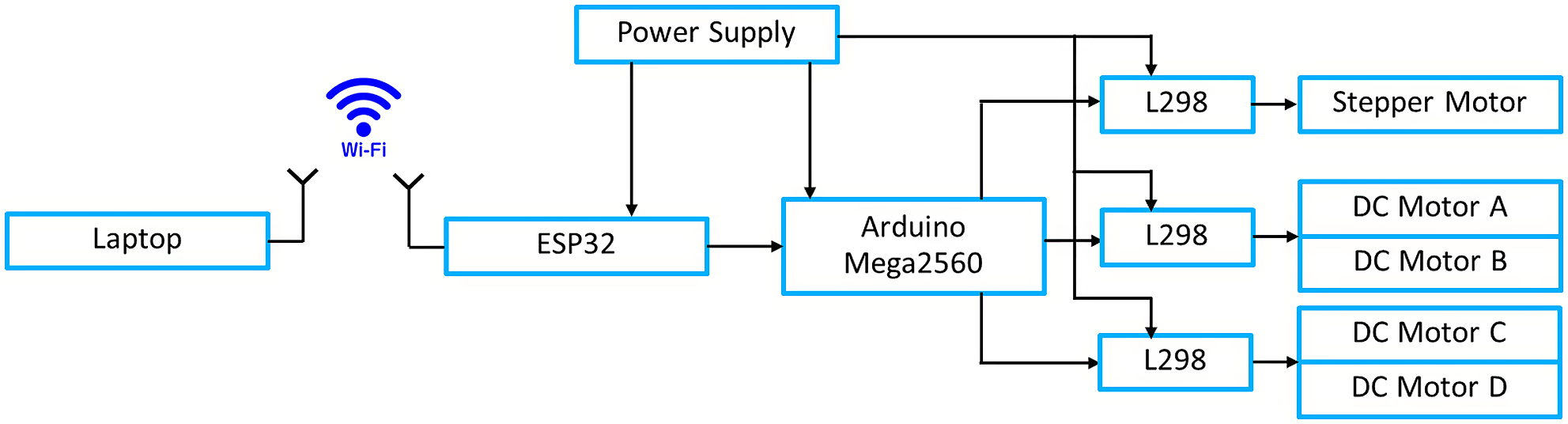
The electrical parts of the robot are in the form of a block diagram shown in Fig. 5.
Block diagram of the robot’s electrical components.

As shown in Fig. 5, the robot is designed with four DC motors to generate linear motion. The DC motors are powered by the L298 (Shenzhen Olearn Technology Co., China) drivers that accept digital input. The PWM method has been used to start and control the speed of these four motors [Reference Fatma and Hamid14]. The amount of displacement is controlled by the duration of the PWM wave applied to the DC motors. For more displacements, the wave duration needs to be longer. The DC motors at idle have a rate of 314 rad/s, but the number of revolutions decreases with the application of the load. To keep the number of revolutions constant, or in other words to reduce the effect of loading, a gearbox connected to the motor shaft is used, which converts the number of revolutions to 3.14 rad/s or half rotation per second when the applied DC voltage is 6 V. Therefore, by increasing and decreasing the PWM pulse width, the rotation speed will increase and decrease, respectively. The presence of the gearbox, in addition to drastically reducing the loading effect during start-up with the load, also acts as a brake and lock at rest, causing the dry skull to remain stationary in a certain position.
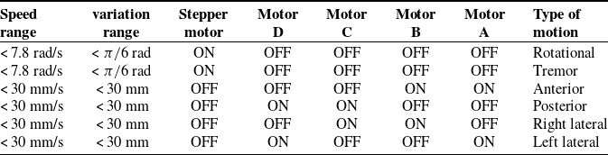
Based on the location of the four DC motors and the stepper motor, six different types of movements are performed as shown in Table I.
According to Table I, the stepper motor in this robot is used to create rotational movements (angular displacement) at different and defined angles. This motor has also been used to create tremor motion. The step of this motor is 1.8 degrees, which is used as a half-step with an angle of 0.9 degrees in this design. Therefore, the accuracy of the displacement angle in this robot is 0.9 degrees. The stepper motor is connected to the Arduino via the L298 driver. Based on the user’s choice of motion, the Arduino executes the required algorithm to drive the stepper motor.
The main part of the robot is its CPU board, which uses the Arduino Mega2560 (Fut-electronic Tech Co, Shenzhen, Guangdong, China). This board is required to execute the motion algorithms written to perform the movements at a given time. Therefore, to design a movement, it is enough to write the necessary program to start DC motors at specific times and program it to the processor through the embedded USB port. As a result, different movements for dry skulls can be designed according to the need in different dental researches.
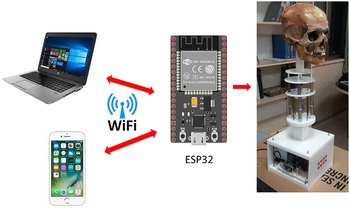
One of the important parts of the designed robot is the Wi-Fi wireless communication unit. The ESP32 (Wemos D1 V1.0.0-Esp32 WiFi and for Bluetooth Module Development Module Cp2104 Development Board, Sunhokey Electronics Co., China) board has been used for this purpose [Reference Maier, Sharp and Vagapov15]. This board is able to communicate with a smartphone or laptop via Wi-Fi as shown in Fig. 6.
The importance of setting up and controlling the robot wirelessly is that the presence of the user is not required to launch the robot during imaging, and this protects the person from being exposed to radiation. The feature of this type of wireless communication is that there is no need for any other application on the smartphone or laptop.
To supply electricity, a switching power supply (MEAN WELL ENTERPRISES CO., Taiwan) is used, which has two outputs, 5 V and 12 V. It has been used for different parts by connecting a series of several diodes in order to reduce the voltage.
Different types of movements using DC motors and stepper motor.

The robot Wi-Fi wireless connection with a smartphone or laptop.

2.3. Kinematic model of the robot
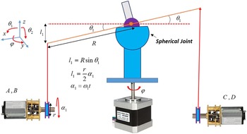
A simple kinematic model of the designed robot is shown in Fig. 7.
A simple kinematic model for the designed cable-driven robot to emulate head movement during the CBCT imaging.

As shown in Fig. 7, the angular displacement of the rotating plate connected to the spherical joint, equal to
 $\theta _{1}$
(Rot(y)), results in a linear displacement in the vertical direction (
 $l_{1}$
) in the x–z plane (anterior–posterior motion). This is done by pulling the flexible cable with the help of the two DC motors A, B and simultaneously releasing the flexible cable by the two DC motors C, D. For angular displacement of
 $\theta _{2}$
(Rot(x)), which consequently results in the linear displacement of
 $l_{2}$
on the y–z plane, it is necessary that the two motors A, D pull the flexible cable and the motors B, C release the flexible cable (lateral movement). The relationships governing this mechanism are given in Eq. (1) and (2).
 \begin{equation*} \boldsymbol{l}_{\mathbf{1}}=\boldsymbol{Rsin}\boldsymbol{\theta }_{\mathbf{1}}=\frac{\boldsymbol{r}}{\mathbf{2}}\boldsymbol{\alpha }_{\mathbf{1}} \end{equation*}
 \begin{equation}\boldsymbol{l}_{\mathbf{2}}=\boldsymbol{Rsin}\boldsymbol{\theta }_{\mathbf{2}}=\frac{\boldsymbol{r}}{\mathbf{2}}\boldsymbol{\alpha }_{\mathbf{2}}\end{equation}
 \begin{equation*} \boldsymbol{\alpha }_{\mathbf{1}}=\boldsymbol{\omega }_{\mathbf{1}}\boldsymbol{t} \end{equation*}
 \begin{equation}\boldsymbol{\alpha }_{\mathbf{2}}=\boldsymbol{\omega }_{\mathbf{2}}\boldsymbol{t}\end{equation}
where
 $\boldsymbol{\alpha }_{\boldsymbol{i}}$
is the amount of rotation of the pulley connected to the end of the motor gearbox (Fig. 7),
 $r$
is the pulley diameter equal to
 $1\,{\rm cm}$
for all four DC motors,
 $\boldsymbol{\omega }_{\boldsymbol{i}}$
is the angular velocity of the motor gearbox in terms of rad/s, and R = 5 cm is the radius of the rotating plate connected to the spherical joint. According to Eqs. (1) and (2), having the angular velocity,
 $\boldsymbol{\omega }_{\boldsymbol{i}}$
, and the running time of the DC motors,
 $t$
, the amount of angular and linear displacement,
 $\boldsymbol{\theta }_{\boldsymbol{i}}$
and
 $\boldsymbol{l}_{\boldsymbol{i}}$
, could be determined. Also, a stepper motor is used to rotate the skull by φ self-rotation. The speed of the rotation depends on the amount of delay between the excitation phases and the step of the stepper motor, which are both completely controllable.
2.4. Setting up the robot in the CBCT imaging system
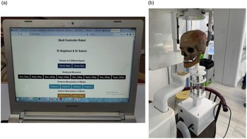
After designing and manufacturing various mechanical and electrical parts of the robot, the robot components are assembled and finally the robot is made. The different parts of the robot have been made in such a way that their connections are performed easily and the possibility of replacing the components can be done quickly. The initial program was programmed for different motions at different speeds on the Arduino board processor. The ESP32 board was programmed for Wi-Fi connection. As soon as the robot is turned on, according to the program written for the ESP32, the Wi-Fi icon related to the robot appears on smartphone or laptop near the robot. Figure 8 shows the control panel page that has been designed for the robot used in this research.
Setting up the robot in the CBCT imaging system. (a) The control panel page after connecting the laptop to the robot via Wi-Fi and (b) placing the robot in the CBCT imaging device.

According to Fig. 8(a), four default motions have been considered for the robot, which are
-
1. Tremor motion of 5 degrees at two different speeds.
-
2. Rotational motion at four different degrees of 5, 10, 15, and 20 with two different adjustable speeds.
-
3. Posterior movement with four different displacements of 5, 10, 15, and 20 mm.
-
4. Anterior movement with two different displacements of 5 and 10 mm at two different speeds.
The position of the robot to perform the motions during CBCT imaging is shown in Fig. 8(b). As mentioned, these movements are defined by default for the robot, and it is possible to combine different movements as needed by reprogramming the processor. For example, performing simultaneous anterior motion with self-rotation movement can create a combination of rotational and anterior motion. An important point in the robot motions planning is that in order to correctly perform the linear motions (anterior, posterior, right lateral, and left lateral movements) and their combinations, one phase of the stepper motor is stimulated; then, the rotational movement is completely locked. This helps a lot to perform the mentioned linear movements accurately. As soon as the aforementioned linear movements are completed, the single-phase excitation of the stepper motor is stopped so that the phase winding is not damaged by heat. To evaluate and analyze images with different motion artifacts, in each type of motion, a reference image is first taken in which the robot does not make any movement. Acrylic balls mounted on dry skull at anterior and posterior regions of maxillary and mandibular alveolar ridge have also been used to investigate the effect of various motion artifacts on imaging quality. The distance between acrylic spheres on both the skull and CBCT images was measured and compared. The distance between two acrylic spheres in images with motion artifacts relative to the motionless reference image is used as an indicator to quantify the amount and intensity of the artifact [Reference Rabelo, Rabelo, Cavalcanti, Pinto, Melo, Campos, Oliveira and Melo16].
Imaging of the dry skull in the nonmoving position and in moving the head was performed by two different CBCT imaging systems. These devices have been used in previous studies [Reference Shokri, Jamalpou, Eskandarloo, Godiny, Amini and Khavid17–Reference Kasraei, Shokri, Poorolajal, Khajeh and Rahmani19]. Table II shows the specifications of these two CBCT systems.
2.5. Statistical analysis
In order to determine the exact amount of linear displacement of the plate connected to the spherical joint, the PWM pulse width method with a frequency of 1 kHz has been used. To do this, the speed of the DC motor is measured by increasing the pulse width. A noncontact optical tachometer (Testo Tachometer 460, Germany) was used to measure the angular velocity (
 $\boldsymbol{\omega }_{\boldsymbol{i}}$
) of the DC motor. Measurements repeated five times and the average of them has been considered. The PWM pulse is applied to the input of the L298 driver and the power input of this driver is connected to a voltage of 12 V. So, for example, if the PWM pulse width is 50%, the average output voltage would be 6 V.
The relationship between the angular velocity and the width of the PWM pulse using linear regression is approximated as follows:
 \begin{equation} \omega \left(rad/s\right)=0.0622PWM\left(\% \right) \end{equation}
By substituting Eq. (3) for Eqs. (1) and (2), we can write
 \begin{equation*} \theta _{1}=\sin ^{-1}\left(\frac{rt}{2R}0.0622PWM_{1}\right) \end{equation*}
 \begin{equation} \theta _{2}=\sin ^{-1}\left(\frac{rt}{2R}0.0622PWM_{2}\right) \end{equation}
The choice of PWM duty cycle and duration
 $t$
is easily possible with the Arduino board processor.
The specifications of the two CBCT imaging systems used in this research.

A MPU6050 gyroscope sensor module ( Mpu6050 Sensor Module, Zhongshan Baijia Dagu Electronic Technology Co., China) was used to measure the angular displacement
 $\theta _{1}$
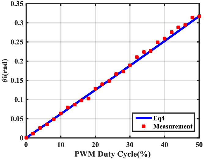
of the chassis on which the dry skull is mounted. For example, for a pulse width of 40%, the measured angular displacement value was 0.26 radian and the obtained value from Eq. (4) was 0.25 radian. This means that if the PWM wave with 40% duty cycle is applied to the DC motors, according to Table I, it can move the dry skull by 0.25 radian in 1 s. The normalized root mean squared error (NRMSE) between the values of these two curves in Fig. 10 is calculated using Eq. (5) as follows:
 \begin{equation} \textit{NRMSE}=100\left(\frac{\sqrt{\sum\limits_{i=1}^{N}\left(\theta _{i}-\overline{\theta }\right)^{2}}}{\sqrt{\sum\limits_{i=1}^{N}\left(\overline{\theta }\right)^{2}}}\right) \end{equation}
where
 $\overline{\theta }$
is the measured average of
 $\theta _{1}$
and
 $\theta _{i}$
is the obtained value of
 $\theta _{1}$
using Eq. (4), and N = 5 is a number of measurements.
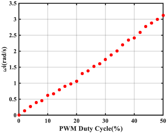
Changes in the angular velocity of the DC motor at the gearbox output (
 $\boldsymbol{\omega }_{\boldsymbol{i}}$
) as the PWM pulse width increases.

Comparison of the
 $\theta _{1}$
values obtained from Eq. (4) and the measured values related to changing the PWM at the t = 1s, r = 1 cm, and R = 5 cm.

3. Results
3.1. Correlation of the DC motor speed with PWM duty cycle
Using Eq. (3), the changes in the speed of the DC motor at the gearbox output in terms of the changes in pulse width from zero to 50% were obtained at 26 points plotted as curve in Fig. 9.
Figure 9 shows the increase in angular velocity of the DC motor with a gearbox with a conversion ratio of 100:1 in terms of pulse width. Although the motor output is measured at no load, the load effect during starting with load will be negligible due to the use of the gearbox with large conversion ratio.
By determining
 $\boldsymbol{\omega }_{\boldsymbol{i}}$
from Eq. (3), the values of
 $\boldsymbol{\alpha }_{\boldsymbol{i}}$
and
 $\boldsymbol{l}_{\boldsymbol{i}}$
can be controlled. For evaluation, the variation curves of
 $\theta _{1}$
using Eq. (4) and measured values of
 $\theta _{1}$
in terms of the PWM changes are plotted in Fig. 10.
Using Eq. (5), the NRMSE value of 4% has been obtained for measured and calculated data of Fig. 10.
3.2. Evaluation of the robot in creating motion artifacts during CBCT imaging
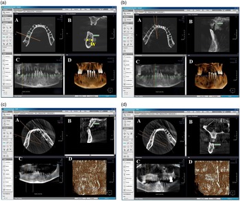
To evaluate the robot’s performance, CBCT imaging was performed in motionless state, rotational motion of 5 degrees, rotational motion of 10 degrees, and linear posterior motion of 5 mm. The imaging results in these cases using the Cranex 3D device are shown in Fig. 11.
Cranex 3D imaging and measurement of the posterior mandibular area from CBCT axial images (A): axial section, (B): cross section, (C): reconstructed panoramic image, and (D): reconstructed 3D image. (a) Reference image (without motion), (b) image with a rotational motion of 5 degree, (c) image with a rotational motion of 10 degrees, and (d) posterior motion of 5 mm.

Before and after making various head movements, CBCT images were prepared and the resulting images were stored in Ondemand software (Cybermed, Seoul, Korea). According to Fig. 11, and the figure corresponding to the axial section (A), the image of the 10-degree rotational motion in part (c) has created more artifacts than the 5-degree rotational motion in part (b). Also, in the image related to the posterior movement of 5 mm (part (d)), the created artifact is much more than the artifact caused by the 10-degree rotational movement.
To study the reproducibility of performing various movements by the robot, the different motions were repeated five times and the NRMSE for them was calculated according to Table III.
According to Table III, the NRMSE obtained for these six different movements is less than 5%. For the self-rotation motion, the obtained error is zero, which indicates that the reproducibility of this motion is 100%.
The quality of the images can be examined in terms of the distance between the two acrylic balls placed on the dry skull at a certain distance from each other. For example, according to Table III, the distance between the two balls for six different movements (W in Fig. 11(a)), along with the value of the motionless image, is given. These distances are measured by the CBCT device software itself. The values obtained for W show that the distance factor between two acrylic balls can be used to quantify the motion effect.
4. Discussion
CBCT imaging has found many applications in implant therapy, endodontics, oral and maxillofacial surgeries, airway evaluation, orthodontic treatment, and evaluation of pathological lesions.
The normal errors between the motionless (reference) CBCT image and the CBCT images with different motion artifacts along with the distance between the two acrylic balls on the dry skull in different CBCT images (W).

One of the challenges in preparing images of the head and neck is the movement of patients’ heads during the image acquisition.
In this research, in order to investigate the effect of different types of head movements during imaging that lead to motion artifacts, a robot has been designed and implemented that is able to execute different motions on a dry skull using four DC motors and a stepper motor. Therefore, the movements created during CBCT imaging are completely controlled, which will be investigated in more detail in our future study. Therefore, with this robot, it is possible to investigate the main factors of motion artifacts in images. In the designed robot, since the four DC motors and the stepper motor are started independently, by launching them in a special order, different movements can be created on the dry skull. However, these six movements including anterior, posterior, rotational, vibratory, right, and left lateral motions were considered. The designed robot was used in a completely isolated CBCT imaging room. Therefore, wireless communication to control the robot is one of the advantages of this robot over the robots used in the previous studies. Also, in the design of this robot, the space constraints created by the CBCT device have been considered. Simultaneously, several intelligent systems can control the robot and launch the desired motions. The rotational motion resolution of this robot is less than one degree and the linear motion is less than 2 mm. All the parts used in this robot are replaceable, and at any stage, when there is a problem for different parts, they can be replaced in a short time.
One of the effective methods for evaluating the quality of images with motion artifacts is to measure the distance between two specific points in the image with artifacts relative to the distance of the same two points in the reference image [Reference Rabelo, Rabelo, Cavalcanti, Pinto, Melo, Campos, Oliveira and Melo16]. These points can be determined using materials that have no effect on the image. For example, acrylic materials would be a good choice for this purpose. Since the reproducibility of performing various motions by the robot is close to 100% (NRMSE < 5%), the effect of different types of motions can be studied by measuring the distance between two points created by acrylic materials.
In a study [Reference Dabaghi, Sharifi, Pur Mehdi Boroujeni, Bayati and Zaheri7] conducted by Arash Dabbaqi et al., the dry skull was able to move in one direction to create a unidirectional linear and rotational motions [Reference Dabaghi, Sharifi, Pur Mehdi Boroujeni, Bayati and Zaheri7]. In addition, it was not possible to combine motions to create lateral head movements in this robot. Also, the robot is set up and controlled manually with a wire connection. The hexapod robot was used by Rubens Spin-Neto et al. to create various dry skull motions. Although the robot was designed for a variety of other purposes, it was capable of moving the dry skull in different directions [Reference Spin-Neto, Matzen, Schropp, Sørensen, Gotfredsen and Wenzel5, Reference Spin-Neto, Matzen, Schropp, Sørensen and Wenzel6]. However, to prevent metal artifacts, it is necessary to design a suitable chassis to connect the dry skull to the robot.
5. Conclusion
One of the main challenges of CBCT imaging is the patient’s movement, which results in motion artifacts during imaging. These motion artifacts greatly reduce the quality of the images, and in many cases, it is necessary to repeat the imaging. In addition to incurring additional costs, this causes the patient to be exposed to radiation for a longer period of time. In this research, a robot has been designed and constructed to create common types of head movements on a dry skull during CBCT imaging. This robot is able to remotely perform various movements of the dry skull during imaging. One of the features of this robot is its wireless connection via Wi-Fi to smart systems such as laptops and smartphones that protect the user from radiation.
Financial support
This work was financially supported by Department of Oral and Maxillofacial Radiology, Dental School, Hamadan University of Medical Sciences, Hamadan, Iran, through the financial agreement number 9911288440.
Conflicts of interest
The authors declare none.
Ethical considerations
None.
Author contributions
RB, MA, and FS conceived and designed the study. RB and MA designed and built the robot. RB, MA, FS, MAL, and MM wrote the article, RB, MA, and MAL edited the article to bring it to its final form.