





1. Introduction
Fluid flow through microchannels offers a wide range of possibilities to control and manipulate transport at very low flow rates
 $({\sim}\unicode{x03BC}\mathrm{l}/\min)$
, where viscous forces dominate and the fluid flow interacts with mechanical properties of bounding walls (Squires & Quake Reference Squires and Quake2005; Bruus Reference Bruus2011; Mehboudi & Yeom Reference Mehboudi and Yeom2019; Park et al. Reference Park, Tixier, Paludan, Østergaard, Zwieniecki and Jensen2021; Kramer & Modes Reference Kramer and Modes2023). These properties make microfluidic platforms suitable for biochemical, lab-on-a-chip and soft microfluidic devices, which can be used to generate controlled droplets at high throughput, facilitating passive mixing, sorting and drug discovery (Chakraborty Reference Chakraborty2010; Raj et al. Reference Raj, Halder, Sajeesh and Sen2016; Koldaeva et al. Reference Koldaeva, Tsai, Shen and Pigolotti2022). In many of these systems, the microchannels are fabricated from soft materials such as polydimethylsiloxane (PDMS) or hydrogels, whose mechanical compliance allows the channel walls to deform in response to fluid stress (Xia & Whitesides Reference Xia and Whitesides1998; Raj et al. Reference Raj, Priyadarshani, Karan, Bandyopadhyay, Bhattacharya and Chakraborty2023; Kawara et al. Reference Kawara, Cunningham, Bezer, Kc, Zhu, Tang, Ishihara, Choi and Au2023). This compliance enables closer emulation of biological transport processes, such as peristaltic flow in blood vessels and nutrient transport through micro- and nanopores (Heil et al. Reference Heil and Hazel2011; Meigel et al. Reference Meigel and Alim2018; Bhattacharyya et al. Reference Bhattacharyya, Zwicker and Alim2023). More broadly, soft substrates including hydrogels and filter papers support fluid transport through a combination of mechanical deformation and chemical interaction with the fluid, giving rise to flow behaviour that can depart markedly from that in rigid channels and exhibits a non-intuitive dynamics (Louf et al. Reference Louf, Knoblauch and Jensen2020; Velde et al. Reference Van de Velde, Dervaux, Duprat and Protière2024; Polygerinos et al. Reference Polygerinos, Correll, Morin, Mosadegh, Onal, Petersen, Cianchetti, Tolley and Shepherd2017; Xu et al. Reference Xu, Heil, Seeböck and Avila2020).
Fluid flow through soft channels is accompanied by deformation of the bounding walls driven by fluid pressure, which in turn feeds back on the flow rate (Duprat et al. Reference Duprat and Stone2015; Karan et al. Reference Karan, Chakraborty, Chakraborty, Wereley and Christov2021; Christov Reference Christov2022; M et al. Reference M, DasGupta and Chakraborty2019). This two-way fluid-structure coupling gives rise to a nonlinear relationship between flow rate and pressure drop
 $(q-\Delta p)$
, enabling passive flow regulation in compliant microfluidic systems (Christov et al. Reference Christov, Cognet, Shidhore and Stone2018; Raj et al. Reference Raj, Chakraborty, DasGupta and Chakraborty2018; Box et al. Reference Box, Peng, Pihler-Puzović and Juel2020). A number of theoretical and analytical studies have characterised this behaviour for various geometries, including thick- and thin-walled rectangular and cylindrical channels, using various constitutive descriptions for both the solid and the fluid (Elbaz & Gat Reference Elbaz and Gat2014, Reference Elbaz and Gat2016; Raj & Sen Reference Raj and Sen2016; Raj et al. Reference Raj, DasGupta and Chakraborty2017; Wang & Christov Reference Wang and Christov2021). In these models, the local channel deformation is expressed solely as a function of fluid pressure, reflecting a purely mechanical forcing (Shidhore & Christov Reference Shidhore and Christov2018; Wang & Christov Reference Wang and Christov2019; Anand & Christov Reference Anand and Christov2021). As a result, such formulations are not suited for describing flow evolution in channels bounded by soft, swelling walls, where deformation arises from coupled mechano-chemical interactions between the fluid and the solid (Dangla et al. Reference Dangla, Gallaire and Baroud2010; Kim et al. Reference Kim, Huang, Choi and Hidrovo2014).
During swelling, a solid absorbs fluid and enlarges, driven by the chemical potential or osmotic pressure differences within the material (Li & Tanaka Reference Li and Tanaka1990; Yoon et al. Reference Yoon, Cai, Suo and Hayward2010). This absorption and the movement of the walls during swelling directly influences the flow in the channel, altering the local flow velocity (Seo et al. Reference Seo, Wang, Chang, Park, Kim and Kim2019). In porous substrates, such as cellulose-based filter papers, swelling can significantly modify fluid transport, affecting reaction kinetics (Masoodi et al. Reference Masoodi, Masoodi and Pillai2010; Chang et al. Reference Chang, Kim and Kim2020). Swelling can also interact with flow instabilities, for example tuning droplet formation through the Rayleigh–Plateau mechanism in co-flow set-ups (González-Estefan et al. Reference González-Estefan, Gonidec, Vu, Daro and Chastanet2019). While these phenomena demonstrate the effect of swelling on flow, the coupled effect of wall compliance and swelling in microchannels remains largely unexplored. This gap motivates a mechanistic study of how swelling-induced channel collapse competes with pressure-driven restraint to shape non-monotonic flow evolution.
During flow of an absorbable fluid through a channel bounded by soft walls, the fluid may diffuse into the polymeric matrix of the solid due to a gradient in the chemical potential (Duprat Reference Duprat2022; Velde et al. Reference Van de Velde, Fabre-Parras, Josserand, Duprat and Protière2023; Yoon et al. Reference Yoon, Cai, Suo and Hayward2010). The absorbed fluid generates internal stresses that deform the solid, a process known as swelling, which in turn modifies the local flow rate along the channel length (Velde et al. Reference Van de Velde, Madkour, Protière and Duprat2025). Previous studies have often employed empirical expressions to describe swelling-induced deformation, such as the linear time dependence:
 $r(t)=r_{0}-at$
, where
 $r_{0}$
is the initial size, and
 $a$
is the rate of change with time (Masoodi et al. Reference Masoodi, Masoodi and Pillai2010; Chang et al. Reference Chang, Kim and Kim2020; Patari et al. Reference Patari, Chowdhury, Kumar and Mahapatra2023). While such formulations capture time-dependent changes in channel dimensions, they conflict with diffusion theory, which predicts a decay in the swelling rate over time, upon absorption. Theoretical models based on chemical-potential-driven absorption, coupled with Biot’s poroelasticity, demonstrate that the swelling kinetics follow an exponential decay
 $({\rm d}r/{\rm d}t\propto e^{-t})$
, a behaviour observed experimentally across materials including textiles, hydrogels in water and PDMS in non-polar solvents (Soltane et al. Reference Soltane, Roizard and Favre2013; Keshmiri et al. Reference Keshmiri, Huang and Nazemifard2019; Chang et al. Reference Chang, Kim and Kim2020). This exponentially decaying rate law defines a characteristic swelling time scale and an amplitude, determined by the mechano-chemical properties of the fluid–solid pair. Chang et al. (Reference Chang, Kim and Kim2020) used this framework to model capillary radius evolution during water imbibition in hydrogel-coated capillaries, and validated the mathematical model against experiments, illustrating how swelling can progressively reduce capillary radius until complete collapse occurs.
For soft-walled channels, swelling-induced collapse increases the fluid pressure under a flow-rate-controlled inlet, which can counteract further closure of the channel, depending on the walls’ compliance and swelling properties. This competition between the two stresses – swelling and fluid pressure, in which the former augments the latter, while the latter opposes the former – may give rise to an intriguing spatio-temporal evolution of flow profile along the channel. The relative strength of these two effects depends critically on the flow conditions, channel geometry and the mechano-chemical properties of both the fluid and the solid.
In this work, we study the incompressible flow of a Newtonian fluid through a shallow rectangular microchannel (width
 $\gg$
height) bounded by soft solids that can swell upon fluid absorption. The system is relevant to both biological and microfluidic contexts, where flow rates are sufficiently low to characterise as low-Reynolds-number hydrodynamics (Kramer & Modes Reference Kramer and Modes2023; Raj et al. Reference Raj, Priyadarshani, Karan, Bandyopadhyay, Bhattacharya and Chakraborty2023). We employ the lubrication approximation to derive unsteady governing equations for the fluid flow through the compliant swelling channel (Panda et al. Reference Panda, Yuet, Dendukuri, Alan Hatton and Doyle2009; Inamdar et al. Reference Inamdar, Wang and Christov2020; Martínez-Calvo et al. Reference Martínez-Calvo, Sevilla, Peng and Stone2020). The net channel deformation depends on the combined effect of swelling kinetics and fluid pressure. For the small swelling ratios considered in this study, we adopt a linear swelling model based on chemical-potential-driven fluid diffusion (Yoon et al. Reference Yoon, Cai, Suo and Hayward2010; Bouklas & Huang Reference Bouklas and Huang2012). For larger swelling ratios, the presented linear model needs to be replaced with nonlinear swelling models (Chen et al. Reference Chen, Huang and Ravi-Chandar2020; Webber & Worster Reference Webber and Worster2023). Combining the lubrication-approximation-based fluid flow governing equation with the spatio-temporally varying deformation yields a nonlinear diffusion equation governing channel height (or fluid pressure) (Martínez-Calvo et al. Reference Martínez-Calvo, Sevilla, Peng and Stone2020). We validate this model with fully coupled direct numerical simulations of the Navier–Stokes equations for the fluid and Navier equations for solid, with fluid diffusion into the solid governed by Fick’s and Darcy’s laws. For weak compliance, we also derive a simplified analytical solution. Using this framework, we explore how swelling and fluid pressure shape the evolution of flow patterns and demonstrate the transition from swelling-dominated to fluid-pressure-dominated regimes, determined by the relative strength of swelling-induced collapse and pressure-mediated restraint.
The paper is organised as follows: the flow configuration is described in § 2. In § 3, we present the mathematical framework for fluid flow, using the lubrication approximation, followed by the modelling of the solid’s deformation. By combining these two frameworks, we derive the final governing equation that describes the coupled physics, along with a simplified analytical solution for weak compliance. In § 4, we outline the set-up for fully coupled direct numerical simulation using the COMSOL Multiphysics platform. In § 5, we present the results, including validation of the mathematical model and approximate analytical solution with the numerical simulations. Finally, in § 6, we summarise the main findings.
2. Flow configuration
We consider incompressible, low-Reynolds-number flow of a Newtonian fluid in a two-dimensional parallel-plate channel of undeformed half-height
 $h_{0f}$
and length
 $l$
, subject to a constant inlet flow rate
 $q(x=0,t)=q_{0}$
, exiting at outlet pressure
 $p=0$
, as illustrated in figure 1. The channel is bounded by soft polymeric layers of thickness
 $h_{0s}$
, which can swell upon fluid absorption, and deform the channel spatio-temporally. The soft solid layers are bonded to rigid surfaces, which impose a zero-displacement constraint at the outer boundaries.
Schematic of the flow domain illustrating the deformation of the solid due to the combined effect of swelling and fluid pressure, subject to a constant inlet flow rate
 $q_{0}$
.

Figure 1. Long description
A diagram of the flow domain illustrating the deformation of the solid due to the combined effect of swelling and fluid pressure, subject to a constant inlet flow rate. The diagram shows a rigid surface at the top and a deformed solid below it. The deformed solid is labeled with various dimensions and variables, including h(x, t), Δ(x, t), h0f, and h0s. The un-swollen solid is depicted below the deformed solid. The diagram includes arrows indicating the direction of flow and the application of fluid pressure. The variables and dimensions illustrate the changes in the solid’s structure due to the fluid pressure and swelling.
We use a Cartesian coordinate system
 $(x,y)$
for the fluid, with
 $x$
-axis along the channel centreline, and the velocity field is denoted by
 $\boldsymbol{v}=(v_{x}, v_{\!y})$
. A separate Cartesian coordinate
 $(x,\xi)$
aligned with the surface of the solid, as shown in figure 1, is used to describe the solid deformation, and to denote the deformation field
 $\boldsymbol{u}=(u_{x}, u_{\xi })$
. The deformation of the solid surface along
 $\xi$
, due to the combined effect of swelling and fluid pressure, is denoted by
 $\varDelta(x,t)$
, as illustrated in figure 1. This deformation reduces the local half-height available for the flow:
 $h(x,t)=h_{0f}-\varDelta(x,t)$
.
In this study, both the channel and solid layers are thin compared with their length, i.e.
 $h_{0f}\ll l$
and
 $h_{0s}\ll l$
, justifying the use of lubrication approximation . We also limit the analysis to the small linear deformation regime
 $\varDelta (x,t)/h_{0s}\lesssim 0.1$
, as detailed in § 3.2.
3. Problem formulation
3.1. Governing equation for flow: lubrication approximation
We consider the unsteady flow of a Newtonian fluid through the two-dimensional channel, whose velocity field
 $\boldsymbol{v}=(v_{x}, v_{\!y})$
is governed by the continuity and Navier–Stokes equations
 \begin{align}\frac{\partial v_{x}}{\partial x}+\frac{\partial v_{\!y}}{\partial y}&=0,\quad\quad\quad\,\,\end{align}
 \begin{align}\rho _{\!f}\left[\frac{\partial v_{x}}{\partial t}+v_{x}\frac{\partial v_{x}}{\partial x}+v_{\!y}\frac{\partial v_{x}}{\partial y}\right]&=-\frac{\partial p}{\partial x}+\eta \left(\frac{\partial ^{2}v_{x}}{\partial x^{2}}+\frac{\partial ^{2}v_{x}}{\partial y^{2}}\right)\!, \end{align}
 \begin{align}\rho _{\!f}\left[\frac{\partial v_{\!y}}{\partial t}+v_{x}\frac{\partial v_{\!y}}{\partial x}+v_{\!y}\frac{\partial v_{\!y}}{\partial y}\right]&=-\frac{\partial p}{\partial y}+\eta \left(\frac{\partial ^{2}v_{\!y}}{\partial x^{2}}+\frac{\partial ^{2}v_{\!y}}{\partial y^{2}}\right)\!, \end{align}
where
 $\rho _{\!f}$
and
 $\eta$
are the fluid’s density and viscosity, respectively, and
 $p$
is the fluid pressure. The
 $x$
-component of fluid velocity satisfies the no-slip condition at the walls, i.e.
 $v_{x}=0$
at
 $y=\pm h(x,t)$
and symmetry at the centreline, i.e.
 $\partial v_{x}/\partial y=0$
at
 $y=0$
. Since, the fluid can penetrate into the solid upon absorption, the net wall-normal velocity at the wall is the algebraic sum of the absorption velocity and wall deformation rate, given by:
 $v_{\!y}=\pm (v_{abs}+\partial h/\partial t)$
at
 $y=\pm h(x,t)$
, where
 $v_{abs}$
is the absorption velocity. At the inlet, the mean velocity is
 $v_{x,m}=q/(2h(0,t))$
, and at the outlet,
 $p=0$
.
We non-dimensionalise the variables using appropriate scales:
 $X=({x}/{l}), Y=({y}/{h_{0f}}), V_{X}=({v_{x}}/{(q/h_{0f})}), V_{Y}=({v_{\!y}}/({\epsilon q/h_{0f}})), P=({p}/{p_{0}})$
and
 $T=({t}/{t_{s}})$
, where
 $p_{0}$
is pressure scale,
 $t_{s}$
is the characteristic swelling time scale and
 $\epsilon =({h_{0f}}/{l})\ll 1$
is the aspect ratio of the channel. The pressure scale
 $p_{0}$
is obtained by equating the scales of axial pressure gradient and the transverse viscous diffusion term on the right-hand side of (3.1b
), yielding
 $p_{0}={lq\eta }/{{h}_{0f}^{3}}$
. Using these scalings, the set of governing equations (3.1a
–
c
) can be written in the non-dimensional form as
 \begin{align}\frac{\partial V_{X}}{\partial X}+\frac{\partial V_{Y}}{\partial Y}&=0,\quad\quad\quad\end{align}
 \begin{align} \textit{ReSt} \frac{\partial V_{X}}{\partial T}+ \textit{Re} V_{X}\frac{\partial V_{X}}{\partial X}+ \textit{Re} V_{Y}\frac{\partial V_{X}}{\partial Y}&=-\frac{\partial P}{\partial X}+\epsilon ^{2}\frac{\partial ^{2}V_{X}}{\partial X^{2}}+\frac{\partial ^{2}V_{X}}{\partial Y^{2}},\end{align}
 \begin{align} {\epsilon } \textit{ReSt} \frac{\partial V_{Y}}{\partial T}+\epsilon \textit{Re} V_{X}\frac{\partial V_{Y}}{\partial X}+\epsilon \textit{Re} V_{Y}\frac{\partial V_{Y}}{\partial Y}&=-\frac{1}{\epsilon }\frac{\partial P}{\partial Y}+ \epsilon ^{3}\frac{\partial ^{2}V_{Y}}{\partial X^{2}}+\epsilon \frac{\partial ^{2}V_{Y}}{\partial Y^{2}},\end{align}
where
 $\textit{Re}=\epsilon \textit{Re}^{*}\ll 1$
is the reduced Reynolds number, such that
 $\textit{Re}^{*}=\rho _{\!f}q/\eta$
is the Reynolds number. Another key dimensionless number appearing in the set of non-dimensional equations is the Strouhal number, which is defined as the ratio of flow time scale
 $(t_{\!f}={lh_{0f}}/{q})$
to swelling time scale
 $(t_{s})$
, given by
 $St=({t_{\!f}}/{t_{s}})=({lh_{0f}}/{q t_{s}})$
. The order of magnitude analysis reduces (3.2c
) to
 $({\partial P}/{\partial Y})\approx 0+O(\epsilon ^{2})$
for
 $\epsilon \ll 1$
. This implies that the fluid pressure remains uniform across the channel height, and varies as
 $P\approx P(X,T)$
. Similarly, (3.2b
) can be written up to leading-order terms
 \begin{equation}\frac{\partial P}{\partial X}=\frac{\partial ^{2}V_{X}}{\partial Y^{2}} .\end{equation}
It should be noted that the unsteady term in the non-dimensionalised
 $X$
-momentum equation, i.e.
 $\textit{ReSt} ({\partial V_{X}}/{\partial T})$
, can be neglected for microfluidic flow because
 $\textit{ReSt}\ll 1$
. This quasi-steady assumption, however, breaks down for
 $St\gg 1$
, where the inertial time-derivative term in (3.2b
) become significant. In the present study, we consider
 $St\lesssim O(1)$
, representing flow and swelling time scales of a similar order, which is consistent with the upper limit for typical microfluidic set-ups (see table 2). After order of magnitude analysis, the leading-order equations, (3.2a
) and (3.3) do not contain an explicit time-derivative term, indicating a quasi-steady flow. Importantly, this quasi-steady behaviour arises from the low-Reynolds-number characteristic of microchannels, rather than the absolute time scales of flow and swelling. Consequently, any temporal variations in the flow field are imposed solely through the boundary conditions.
The spatio-temporally varying flow rate can be obtained by integrating (3.2a
) along the half-height of the domain (due to symmetry) from
 $Y=0$
to
 $Y=H(X,T)$
, where
 $H(X,T)=h(x,t)/h_{0f}$
, yielding
 \begin{equation}\frac{1}{2}\frac{\partial Q(X,T)}{\partial X}+V_{Y}\left(X,Y=H,T\right)=0,\end{equation}
with
 $Q(X,T)=2{\int }_{0}^{H(X,T)}V_{X}{\rm d}Y$
. While integrating (3.2a
), we have used Leibniz integral rule with the no-slip boundary condition at the wall, i.e.
 $V_{X}(X,Y=H,T)=0$
, and symmetry at the centreline
 $V_{Y}(X,Y=0,T)=0$
. For weakly swelling materials, the swelling rate is typically proportional to the rate of fluid absorption, i.e.
 $v_{abs}\propto \partial h_{s}/\partial t$
(Chang et al. Reference Chang, Jensen, Kim and Kim2022), therefore, the net fluid velocity along the
 $Y$
-direction at the wall can be expressed as
 \begin{equation}V_{Y}\left(X,Y=H,T\right)=(1-\alpha)\frac{\partial H}{\partial T},\end{equation}
where
 $\alpha$
is the ratio of absorption rate to swelling rate. For
 $\alpha \gt 1$
, absorption rate into the solid exceeds the swelling rate, so
 $V_{Y}(X,Y=H,T)\gt 0$
, as the channel gap reduces
 $\partial H/\partial T\lt 0$
, and vice versa. Substituting (3.5) into (3.4) gives
 \begin{equation}\frac{1}{2}\frac{\partial Q(X,T)}{\partial X}+(1-\alpha)\frac{\partial H}{\partial T}=0,\end{equation}
which represents the mass conservation equation in integral form, and can also be derived from the Reynolds transport theorem.
The axial velocity profile
 $V_{X}$
at a given streamwise location
 $X$
is obtained by integrating (3.3) twice with respect to
 $Y$
, subject to: (i) symmetry at the centreline:
 $({\partial V_{X}}/{\partial Y})_{Y=0}=0$
, and (ii) a no-slip condition at the wall:
 $V_{X}(X,Y=H,T)=0$
, which yields the parabolic velocity profile
 \begin{equation}V_{X}\left(X,Y,T\right)=-\frac{1}{2}\frac{\partial P(X,T)}{\partial X}\big(H^{2}-Y^{2}\big).\end{equation}
Integrating (3.7) along the channel height gives the local flow rate
 \begin{equation}Q(X,T)=-\frac{2}{3}H^{3}(X,T)\frac{\partial P}{\partial X}.\end{equation}
Substituting (3.8) into the mass conservation relation (3.6) leads to
 \begin{equation}(1-\alpha)\frac{\partial H(X,T)}{\partial T}=\frac{1}{3}\frac{\partial }{\partial X}\left[H^{3}(X,T)\frac{\partial P}{\partial X}\right]\!. \end{equation}
The prefactor
 $(1-\alpha)$
quantifies the relative importance of swelling-induced deformation compared with fluid absorption, and therefore, governs whether the flow rate increases or decreases along the channel length, as implied by (3.6). To close (3.9), we need to specify the relation linking the channel height
 $H(X,T)$
and fluid pressure
 $P(X,T)$
, via swelling kinetics. This enables (3.9) to be cast as a nonlinear diffusion equation in either
 $H(X,T)$
or
 $P(X,T)$
, subject to appropriate boundary conditions.
3.2. Deformation due to swelling and fluid pressure
The swelling kinetics of polymeric solids have been extensively studied by combining fluid diffusion into the porous network with the resulting deformation using the theory of poroelasticity (Tanaka & Fillmore Reference Tanaka and Fillmore1979; Li & Tanaka Reference Li and Tanaka1990; Liu et al. Reference Liu, Robisson, Lou and Suo2013). Earlier models employed linear poroelasticity, assuming strain-independent material properties (Yoon et al. Reference Yoon, Cai, Suo and Hayward2010; Drozdov et al. Reference Drozdov, Sommer-Larsen, de Claville Christiansen and Sanporean2014). However, for large swelling ratios
 $({\sim}100\,\%)$
, this assumption fails due to significant changes in material properties, such as permeability and elastic modulus. Several nonlinear models have been developed to capture swelling kinetics under such conditions (Bouklas & Huang Reference Bouklas and Huang2012; Webber & Worster Reference Webber and Worster2023). Linear models, while accurate for predicting deformation over time for moderate swelling ratios
 $({\sim}50\,\%)$
, cannot reliably predict stress, limiting their applicability to low swelling ratios
 $({\lesssim}20\,\%)$
. In the present study, we consider weakly swelling materials, with swelling ratios
 ${\sim}10\,\%$
, allowing the use of a linear swelling model, and neglecting changes in material properties upon deformation. For large swelling ratios, nonlinear models are required, which is beyond the scope of the present work (Kvick et al. Reference Kvick, Martinez, Hewitt and Balmforth2017).
The coupling between the fluid flow and solid mechanics involves three distinct time scales: the elastic deformation time scale
 $t_{d}\sim \sqrt{{\rho _{s}{h}_{0s}^{2}}/{E}}$
, the convective flow time scale
 $t_{\!f}\sim lh_{0f}/q$
and the swelling time scale
 $t_{s}$
. For the characteristic material properties and dimensions considered in this study (see table 1), the elastic time scale is approximately
 $t_{d}\sim O(10^{-4}) s$
, whereas the flow and swelling time scales are significantly larger,
 $t_{\!f}, t_{s}\gtrsim 10 \, s$
. Given that
 $t_{d}\ll t_{\!f}$
and
 $t_{d}\ll t_{s}$
, the solid reaches mechanical equilibrium much faster than the time required for significant fluid transport or swelling to occur. Consequently, we assume the elastic response of the channel walls to the fluid pressure is instantaneous.
Upon deformation, the infinitesimal strain tensor
 $s_{ij}$
in the solid is related to the displacement field
 $\boldsymbol{u}$
as
 \begin{equation}s_{ij}=\frac{1}{2}\left(\frac{\partial u_{i}}{\partial x_{\!j}}+\frac{\partial u_{\!j}}{\partial x_{i}}\right)\!, \end{equation}
where
 $u_{m}$
denotes displacements in mth-direction,
 $m=x,y$
. Deformation of the solid leads to storage of the free energy, comprising elastic energy and the chemical potential energy associated with the absorbed fluid. The corresponding variation of the Helmholtz free energy may be written as (Yoon et al. Reference Yoon, Cai, Suo and Hayward2010)
 \begin{equation}\delta W=\sigma _{ij}\delta s_{ij}+\left(\mu -\mu _{0}\right)\delta c,\end{equation}
where
 $\mu (x_{i}, x_{\!j}, t)$
is the chemical potential of the absorbed fluid,
 $\mu _{0}$
is its reference value, and
 $c$
denotes the fluid concentration.
The swelling-induced volumetric strain corresponds to the volume of absorbed fluid, and is therefore proportional to the concentration change, such that
 $\delta s_{kk}=a\Omega \delta c$
, where
 $a$
is a proportionality constant, and
 $\Omega$
is the molecular volume of the fluid. Substituting this relation into (3.11) and differentiating with respect to the strain yields the stress tensor
 \begin{equation}\sigma _{ij}=\frac{\delta W}{\delta s_{ij}}-\frac{\left(\mu -\mu _{0}\right)}{a\Omega }\delta _{ij},\end{equation}
where
 $\delta _{ij}$
is the Kronecker delta. Within the framework of linear elasticity, the elastic free energy density is given by
 $W=G[s_{ij}s_{ij}+({\nu }/{(1-2\nu)}){s}_{kk}^{2}]$
, where
 $G$
is the shear modulus, and
 $\nu$
is Poisson’s ratio. Substituting into (3.12) yields the relation for the stress tensor
 \begin{equation}\sigma _{ij}=2G\left[s_{ij}+\frac{\nu }{1-2\nu }s_{kk}\delta _{ij}\right]-\frac{\left(\mu -\mu _{0}\right)}{a\Omega }\delta _{ij}.\end{equation}
The material properties of the solid are assumed to remain constant throughout the swelling, consistent with the assumption of weak swelling. The quasi-static mechanical equilibrium of the solid is then governed by Cauchy’s momentum equation
 \begin{equation}\frac{\partial \sigma _{ij}}{\partial x_{\!j}}=0.\end{equation}
Since the in-plane dimensions of the solid are much larger than the thickness, i.e.
 $h_{0s}\ll l$
, the fluid absorption and subsequent swelling occur predominantly along the thickness, i.e. the
 $\pm \xi$
-direction. Consequently, the in-plane strain remains negligible, i.e.
 $s_{xx}\ll s_{\xi \xi }$
. Therefore, the relevant stress balance equation along the
 $\xi$
direction is given by
 \begin{equation}\frac{\partial \sigma _{\xi x}}{\partial x}+\frac{\partial \sigma _{\xi \xi }}{\partial \xi }=0.\end{equation}
Using the characteristic deformation scale
 $u_{c}$
along the
 $\xi$
-direction, the stress components scale as
 $\sigma _{x\xi }\sim Gu_{c}/l $
and
 $\sigma _{\xi \xi }\sim Gu_{c}/h_{0s}$
. Substitution into (3.15) shows that the first term scales as
 $u_{c}/l^{2}$
, while the second term varies as
 $u_{c}/{h}_{0s}^{2}$
. Since
 $h_{0s}\ll l$
, the stress balance equation reduces to
 \begin{equation}\frac{\partial \sigma _{\xi \xi }}{\partial \xi }=0.\end{equation}
The solid surface in contact with the fluid experiences a normal compressive stress equal to the fluid pressure, such that
 $\sigma _{\xi \xi }(\xi =0)=-p$
. Using this boundary condition in (3.16) implies
 $\sigma _{\xi \xi }=-p$
throughout the solid thickness. Substituting this condition into (3.13) leads to
 $\sigma _{\xi \xi }=(\lambda +2G)s_{\xi \xi }-({(\mu -\mu _{0})}/{a\Omega})$
, which upon re-arrangement, yields
 \begin{equation}s_{\xi \xi }=\frac{\partial u_{\xi }}{\partial \xi }=-\frac{p}{\lambda +2G}+\frac{1}{\lambda +2G}\frac{\mu -\mu _{0}}{a\Omega },\end{equation}
where
 $\lambda =({2\nu }/{(1-2\nu)})G$
is Lamé’s first parameter. Equation (3.17) shows that the total strain can be decomposed as
 $s_{\xi \xi }=s_{\!p}+s_{s}$
, where
 $s_{\!p}$
arises from fluid pressure, and
 $s_{s}$
from swelling. The swelling-induced strain is thus
 \begin{equation}s_{s}=\frac{\partial u_{s}}{\partial \xi }=\frac{1}{\lambda +2G}\frac{\mu -\mu _{0}}{a\Omega }.\end{equation}
The diffusion of fluid within the solid is governed by the conservation equation
 \begin{equation}\frac{\partial c}{\partial t}+\frac{\partial J_{\xi }}{\partial \xi }=0,\end{equation}
where the flux is driven by the chemical potential gradient
 $J_{\xi }=-({K}/{\eta \Omega ^{2}}) ({\partial \mu }/{\partial \xi})$
, and
 $K$
is the permeability. Combining (3.18) and (3.19) with the relation
 $\delta s_{s}=a\Omega \delta c$
yields a diffusion equation for the swelling-induced strain
 \begin{equation}\frac{\partial s_{s}}{\partial t}=D\frac{\partial ^{2}s_{s}}{\partial \xi ^{2}},\end{equation}
where
 $D=({Ka^{2}(\lambda +2G)})/{\eta }$
is the effective diffusion coefficient. Equation (3.20) is subject to the initial condition
 $s_{s}(\xi , t=0)=0$
. At the fluid–solid interface
 $\xi =0$
, the chemical potential remains constant at
 $\mu =\overline{\mu }$
, which implies
 $s_{s}=({1}/{(\lambda +2G)}) ({(\overline{\mu }-\mu _{0})}/{a\Omega})$
. At the bottom surface
 $\xi =-h_{0s}$
, which is rigid and impermeable, the no-flux condition yields
 $\partial s_{s}/\partial \xi =0$
. Solving the linear diffusion (3.20) subject to these conditions yields
 \begin{align} s_{s}=\frac{1}{\lambda +2G}\frac{\overline{\mu }-\mu _{0}}{a\Omega } \left[1+{\sum }_{n=0}^{\infty }\frac{4}{\pi (2n+1)}\exp \left\{-(2n+1)^{2}\frac{t}{t_{s}}\right\}\sin \left\{\frac{(2n+1)\pi }{2h_{0s}}\xi \right\}\right]\!, \end{align}
where
 $t_{s}=4{h}_{0s}^{2}/\pi ^{2}D$
is the characteristic swelling time scale of the solid, which is similar to the diffusion time scale
 $\propto$
length2
 $/$
diffusion coefficient. Equation (3.21) can be integrated along the thickness to obtain the displacement field in the solid due to swelling, imposing zero displacement at the rigid surface, i.e.
 $u_{s}(\xi =-h_{0s},t)=0$
, yielding
 \begin{align} u_{s}=\frac{1}{\lambda +2G}\frac{\overline{\mu }-\mu _{0}}{a\Omega } \left[(\xi +h_{0s})-{\sum }_{n=0}^{\infty }\frac{8h_{0s}}{\pi ^{2}(2n+1)^{2}}\exp \left\{-(2n+1)^{2}\frac{t}{t_{s}}\right\}\cos \left\{\frac{(2n+1)\pi }{2h_{0s}}\xi \right\}\right]\!. \end{align}
The swelling amplitude can be obtained by evaluating the surface displacement at
 $\xi =0$
in the long-time limit
 $t\rightarrow \infty$
, resulting in
 \begin{equation} \varDelta_{s,\infty }=\frac{h_{0s}}{\lambda +2G}\frac{\overline{\mu }-\mu _{0}}{a\Omega },\end{equation}
which represents the maximum swelling magnitude. Using (3.23) to normalise (3.22), the instantaneous swelling magnitude can be expressed in the dimensionless form as
 \begin{equation}\frac{\varDelta _{\mathrm{s}}}{\varDelta _{s,\infty }}=1-{\sum }_{n=0}^{\infty }\frac{8}{\pi ^{2}\left(2n+1\right)^{2}}\exp \big[-(2n+1)^{2}T\big]\equiv \mathcal{F}_{n}(T),\end{equation}
where
 $T=t/t_{s}$
is the dimensionless time. Several experimental studies of swelling kinetics approximate the transient swelling response using a single exponential form
 \begin{equation}\frac{\varDelta _{s}(T)}{\varDelta _{s,\infty }}=1-\exp \left(-T\right),\end{equation}
which captures the long-time behaviour.
We compare the truncated series solution given by (3.24) for different values of
 $n$
, as well as the single exponential approximation given by (3.25), with results from direct numerical simulations performed using COMSOL Multiphysics, as shown in figure 2. The details of the simulation methodology are provided in § 4. The single exponential model given by (3.25) systematically underpredicts the swelling magnitude at early time, with a maximum deviation of
 ${\sim}0.14$
, although it converges towards the simulation results at later times. In contrast, the series solution, (3.24), exhibits better agreement over the entire time range, despite the presence of initial truncation error
 $\mathcal{F}_{n}(T=0)\neq 0$
. Increasing
 $n$
reduces this error, bringing
 $\mathcal{F}_{n}(T=0)$
closer to its ideal value of
 $0$
. For
 $n=5$
, the deviation is less than
 $3\,\%$
, and hence we adopt
 ${\varDelta_{\mathrm{s}}(T)}/{\varDelta _{s,\infty }}=\mathcal{F}_{5}(T)$
to estimate the swelling magnitude in subsequent analyses.
Temporal evolution of the normalised swelling magnitude
 $\varDelta _{s}/\varDelta _{\infty }$
, comparing the truncated series solution
 $\mathcal{F}_{n}(T)$
given by (3.24) for different values of
 $n$
, the single exponential approximation given by (3.25), and results from direct numerical simulations.

The deformation induced by fluid pressure is obtained by integrating the corresponding strain component from (3.17),
 $s_{\!p}=-({p}/{(\lambda +2G)})$
. Defining the compliance parameter
 $\varrho ={p_{0}}/{(\lambda +2G)}$
as the ratio between the viscous pressure scale and the elastic stiffness of the solid, the strain due to fluid pressure simplifies to
 $s_{\!p}=({\partial u_{\!p}}/{\partial \xi })=-P\varrho$
, where
 $P$
is dimensionless fluid pressure. Imposing the boundary condition of zero displacement at the rigid base, i.e.
 $u_{\!p}=0$
at
 $\xi =-h_{0s}$
, the deformation of the fluid–solid interface at
 $\xi =\varDelta _{s}$
due to fluid pressure is given by
 \begin{equation}\varDelta _{\!p}=-P\varrho \left(\varDelta _{s}(T)+h_{0s}\right).\end{equation}
Combining (3.24) and (3.26), the total deformation at any streamwise location,
 $\varDelta (X,T)=\varDelta _{s}+\varDelta _{\!p}$
, is given by
 \begin{equation}\varDelta (X,T)=\varDelta _{s}(T)-\varrho P(X,T)\left(\varDelta _{s}(T)+h_{0s}\right).\end{equation}
The half-height of the deformed channel can be obtained by subtracting the net solid deformation from the initial height, which, in dimensionless form, becomes
 \begin{equation}H(X,T)=1-\frac{\varDelta (X,T)}{h_{0f}}=A(T)+B(T)P(X,T),\end{equation}
where
 $A(T)=1-({\varDelta _{s}}/{h_{0f}})=1-\beta \mathcal{F}_{n}(T)$
and
 $B(T)=\varrho ({(\varDelta _{s}+h_{0s})}/{h_{0f}})=\varrho (\beta \mathcal{F}_{n}(T)+\mathscr{r})$
. Here,
 $\beta =\varDelta _{s,\infty }/h_{0f}$
measures the extent of channel collapse due to swelling, and
 $\mathscr{r}=h_{0s}/h_{0f}$
is the ratio of solid thickness to initial half-height of the channel. These parameters govern the relative influence of swelling-induced expansion and fluid-pressure-induced compression, which act in opposing directions to determine the instantaneous channel geometry.
3.3. Diffusion equation for channel height
In (3.28), we express the spatio-temporal variation in half-channel height
 $H(X,T)$
as a linear function of
 $P(X,T)$
. Rearranging (3.28), the fluid pressure can be written in terms of
 $H(X,T)$
as
 \begin{equation}P(X,T)=\frac{H(X,T)-A(T)}{B(T)},\end{equation}
which, upon substitution in (3.9), yields a nonlinear diffusion equation governing the evolution of channel height
 \begin{equation}(1-\alpha)\frac{\partial H(X,T)}{\partial T}=\frac{1}{3}\frac{\partial }{\partial X}\left[\frac{H^{3}(X,T)}{B(T)}\frac{\partial H(X,T)}{\partial X}\right]\!. \end{equation}
Equation (3.30) needs to be solved subject to the following initial and boundary conditions:
 \begin{equation}{\rm initial\,condition}\colon\quad H(X,0)=1,\end{equation}
 \begin{equation}{\rm inlet\,(flow\hbox{-}rate\hbox{ }controlled)}\colon\quad \frac{\partial H(0,T)}{\partial X}+\frac{3B(T)}{2H^{3}(0,T)}=0,\end{equation}
 \begin{equation}{\rm outlet\,(zero\,pressure)\colon}\quad H(X=1,T)=A(T).\end{equation}
Here, the inlet boundary condition is obtained by combining (3.6), (3.8) and (3.29), for a constant imposed inlet flow rate
 $Q(X=0,T)=1$
.
We solve this nonlinear diffusion equation (3.30) subject to the initial condition (3.31a
) and the boundary conditions (3.31b
–
c
) using the LinearLUSolver class of the FiPy package in Python. FiPy is a Python-based partial differential equation solver package based on the finite volume method. It discretises the governing equation over the computational mesh, resulting in a system of algebraic equations, which is solved using the lower–upper (LU) factorisation method by LinearLUSolver. We discretise the domain
 $X\in [0, 1]$
into 80 uniform grid cells, corresponding to grid size
 $\Delta X=1/80$
to form one-dimensional linear cells. Time integration was performed using a uniform time step
 $\Delta T=5\times 10^{-3}$
. At each time step, a maximum of 50 solver iterations was allowed, with a convergence tolerance of
 $10^{-4}$
.
3.4. Analytical solution for
 $\varrho \ll 1$

In the limit of a very small compliance ratio,
 $\varrho \ll 1$
, the deformation induced by fluid pressure remains weak, implying
 $B(T)\ll 1$
. Under this small deformation limit, the nonlinear diffusion equation (3.30) can be expanded to leading order in
 $B$
, reducing it to an ordinary differential equation in
 $X$
 \begin{equation}\frac{\partial }{\partial X}\left[H^{3}\frac{\partial H(X,T)}{\partial X}\right]=3B(1-\alpha)\frac{{\rm d}A(T)}{{\rm d}T}.\end{equation}
Equation (3.32) may alternatively be obtained by approximating
 $({\partial H(X,T)}/{\partial T})\approx ({{\rm d}A(T)}/{{\rm d}T})$
in (3.6). This approximation neglects the contribution of fluid-pressure-induced deformation on the axial variation of the flow rate, which is justified when the swelling time scale
 $t_{s}$
is large compared with the elastic response time of the solid. In this regime, axial variations in flow rate arise predominantly from swelling-induced displacement and fluid absorption.
Introducing the transformation
 $G(X,T)=H^{4}(X,T)$
, (3.32) can be rewritten as
 \begin{equation}\frac{\partial ^{2}G(X,T)}{\partial X^{2}}=12B(1-\alpha)\frac{{\rm d}A(T)}{{\rm d}T}.\end{equation}
The corresponding initial and boundary conditions transform to
 \begin{equation}{\rm initial\,condition}\colon:\quad G(X,0)=1,\end{equation}
 \begin{equation}{\rm inlet\,(flow\hbox{-}rate\,controlled)\colon}\quad \frac{\partial G(0,T)}{\partial X}+6B(T)=0,\end{equation}
 \begin{equation}{\rm outlet\,(zero\,pressure)\colon}\quad G(X=1,T)=A^{4}(T).\end{equation}
We integrate the (3.33) twice with respect to
 $X$
, and applying the conditions (3.33a
–
c
) yields the analytical expression for the half-height of the channel
 \begin{equation}H(X,T)=\left[A^{4}(T)-6B(T)(1-\alpha) \frac{dA(T)}{dT}\big(1-X^{2}\big)+6B(T)\left(1-X\right) \right]^{\frac{1}{4}}\!. \end{equation}
At early times,
 $T\ll 1$
, we have
 $B(T)=\varrho (\beta \mathcal{F}_{n}(T)+\mathscr{r})\sim \varrho \mathscr{r}\ll 1$
and
 $A(T)\approx 1$
, so that
 $H(X,T)\approx A(T)$
, with the remaining terms in (3.34) being negligible. In contrast, at later times,
 $T\gg 1$
, the ratio
 $B/A^{4}$
may become
 $O(10^{-1}-1)$
for sufficiently large
 $\varrho$
and
 $\beta$
. In this regime, the second and third terms on the right-hand side of (3.34), corresponding to fluid-pressure-induced deformation, become comparable to the swelling contribution represented by the first term. This behaviour arises from the sharp increase in fluid pressure upon channel collapse due to swelling, which can lead to substantial deformation of the compliant, swelling solid.
4. Fully coupled numerical simulation
4.1. Governing equations
The governing equations for the fluid are the continuity and momentum balance equations
 \begin{equation}\rho _{\!f}\boldsymbol{\nabla }\boldsymbol{\cdot }\boldsymbol{v}=0,\end{equation}
 \begin{equation}\rho _{\!f}\frac{\partial \boldsymbol{v}_{\boldsymbol{f}}}{\partial t}+ \rho _{\!f}\left(\boldsymbol{v}\boldsymbol{\cdot }\boldsymbol{\nabla }\right)\boldsymbol{v}=\boldsymbol{\nabla }\boldsymbol{\cdot }\big[-p\boldsymbol{I}+\eta \big(\boldsymbol{\nabla }\boldsymbol{v}+(\boldsymbol{\nabla }\boldsymbol{v})^{T}\big)\big],\end{equation}
where
 $\boldsymbol{v}$
is the fluid velocity vector,
 $\rho _{\!f}$
is the density,
 $\eta$
is the viscosity,
 $p$
is the fluid pressure and
 $\boldsymbol{I}$
is the unit tensor.
The deformable solid is modelled as a linear elastic material, whose deformation is governed by the balance of linear momentum
 \begin{equation}\rho _{s}\frac{\partial ^{2}\boldsymbol{u}}{\partial t^{2}}=\boldsymbol{\nabla }\boldsymbol{\cdot }\left(\boldsymbol{FS}\right)^{T}+\boldsymbol{F}_{\!V},\end{equation}
where
 $\boldsymbol{u}$
is the deformation field,
 $\rho _{s}$
the solid density and
 $\boldsymbol{F}_{\!V}$
is the body force, which is neglected in the present study. The deformation gradient tensor
 $\boldsymbol{F}$
is defined as
 \begin{equation}\boldsymbol{F}=\boldsymbol{I}+\boldsymbol{\nabla }\boldsymbol{u}.\end{equation}
The net strain tensor is written as
 \begin{equation}\boldsymbol{E}=\boldsymbol{E}_{\boldsymbol{el}}+\boldsymbol{E}_{\boldsymbol{sw}}=\frac{\mathbf{1}}{\mathbf{2}}\big(\boldsymbol{F}^{\boldsymbol{T}}\!\boldsymbol{F}-\boldsymbol{I}\big),\end{equation}
where
 $\boldsymbol{E}_{\boldsymbol{el}}$
and
 $\boldsymbol{E}_{\boldsymbol{sw}}$
denote elastic strain and contribution due to swelling, respectively. The swelling-induced strain remains proportional to the absorbed fluid concentration
 \begin{equation}\boldsymbol{E}_{\boldsymbol{sw}}=\beta _{h}M_{m}(c-c_{0}),\end{equation}
where
 $\beta _{h}$
is the swelling coefficient,
 $M_{m}$
is the molar mass of the fluid and
 $c_{0}$
is the reference concentration in the solid, taken here as
 $c_{0}=0$
. The second Piola–Kirchhoff stress tensor
 $\boldsymbol{S}$
is related to the Cauchy stress
 $\sigma _{s}$
by
 \begin{equation}\boldsymbol{S}=\mathcal{J}\boldsymbol{F}^{-\mathbf{1}}\boldsymbol{\sigma }_{\boldsymbol{s}}\boldsymbol{F}^{-\boldsymbol{T}},\end{equation}
where
 $\mathcal{J}=\det (\boldsymbol{F})$
. Assuming isotropic linear elasticity, the constitutive relation is given by the Saint Venant–Kirchhoff model, which extends Hooke’s law to account for finite deformations
 \begin{equation}\boldsymbol{S}=\lambda \left(\mathrm{tr} \boldsymbol{E}\right)\boldsymbol{I}+2G\boldsymbol{E}.\end{equation}
The evolution of absorbed fluid concentration within the solid is governed by Fickian diffusion
 \begin{equation}\frac{\partial c}{\partial t}=\boldsymbol{\nabla }\boldsymbol{\cdot }\left(D_{0}\boldsymbol{\nabla }c\right),\end{equation}
where
 $D_{0}$
is the diffusion coefficient.
At the fluid–solid interface, the continuity of velocity and traction is enforced
 \begin{equation}\boldsymbol{v}=\frac{\partial \boldsymbol{u}}{\partial t},\end{equation}
 \begin{equation}\boldsymbol{n}\boldsymbol{\cdot }\boldsymbol{\sigma }_{\boldsymbol{s}}=\boldsymbol{n}\boldsymbol{\cdot }\big[-p\boldsymbol{I}+\eta \big(\boldsymbol{\nabla }\boldsymbol{v}+ (\boldsymbol{\nabla }\boldsymbol{v})^{T}\big)\big], \end{equation}
where
 $\boldsymbol{n}$
is a unit vector normal to the solid boundary. This equation enforces the continuity of traction across the fluid–solid interface, where
 $\boldsymbol{\sigma }_{\boldsymbol{s}}=\mathcal{J}^{-1}\boldsymbol{FS}\boldsymbol{F}^{\boldsymbol{T}}$
is the Cauchy stress tensor in the solid domain, and the right-hand side represents the total fluid stress acting on the interface. This fully coupled system of fluid flow, solid deformation and fluid diffusion equations is solved numerically using the finite-element-based method in COMSOL Multiphysics environment.
The simulations were performed in two dimensions over the half-height of the channel, exploiting symmetry about the centreline, as illustrated in figure 3(a). Fluid enters the channel from the inlet at a prescribed constant flow rate and exits at the outlet at zero pressure. The swelling solid is bonded to a rigid, impermeable surface, where both displacement and fluid flux are set to zero. At the lateral boundaries of the solid domain
 $(x=0$
and
 $x=l)$
, roller constraints are imposed to enforce a zero-displacement condition in the longitudinal direction
 $u_{x}=0$
. This ensures that the solid edges remain fixed axially, while permitting unconstrained deformation in the transverse direction
 $(y$
-direction) due to swelling and fluid pressure.
(a) Schematic of the computational domain used for simulations. (b) Comparison of the spatio-temporal evolution of the half-height of the channel, normalised by its inlet value at the corresponding time,
 $\overline{H}(X,T)=H(X,T)/H(0,T)$
. Results obtained from the numerical solution of the nonlinear diffusion equation (3.30) and its approximate analytical solution (3.34) are compared with direct numerical simulations performed in COMSOL Multiphysics. Parameters:
 $\beta =0.8, \mathscr{r}=8, \varrho =1.5\times 10^{-5}$
.

It should be noted that the roller boundary condition ensures that the solid is free to deform only along the
 $y$
-direction at the inlet. However, this boundary condition is a significant simplification of real-world experimental systems, such as those reported by Gervais et al. (Reference Gervais, El-Ali, Günther and Jensen2006), Hardy et al. (Reference Hardy, Uechi, Zhen and Pirouz Kavehpour2009) and Raj M et al. (Reference Raj, Chakraborty, DasGupta and Chakraborty2018). Consequently, the present analysis is valid outside the boundary layers, far from the injection points (Christov et al. Reference Christov, Cognet, Shidhore and Stone2018). In experimental realisations of flow through soft channels, deformations in boundary layers lead to intriguing fluid–structure interaction (FSI) phenomena, such as choking, which are discussed by Box et al. (Reference Box, Peng, Pihler-Puzović and Juel2020) and Peng et al. (Reference Peng, Cuttle, MacMinn and Pihler-Puzović2023).
4.2. Numerical method
The fully coupled fluid–structure diffusion problem is solved using COMSOL Multiphysics, which employs the finite element method to simulate multiphysics interactions. The governing equations for fluid flow, solid deformation and fluid diffusion, given by equations (4.1), (4.2), (4.3) and (4.9), were cast into their weak forms and discretised over the computational domain. Both the fluid and solid domains are discretised using triangular finite elements. To accurately resolve gradients near the fluid–solid interface, locally refined, structured elements are employed in this region. Mesh motion arising from solid deformation is handled using COMSOL’s built-in arbitrary Lagrangian–Eulerian formulation. The governing equations are integrated in time using a variable-step backward differential formula method with relative tolerance of
 $10^{-3}$
. Within each time step, nonlinearities are handled via the Newton method. The resulting linearised sub-problems are solved using the parallel direct sparse solver direct solver, which ensures that the linear residuals are reduced to the limit of machine precision. The mesh-independence test results are provided in Appendix A. The final mesh utilised ensured that the numerical results are independent of the spatial discretisation.
Physical parameters.

Table 1. Long description
A table with three columns: Parameters, Symbol, and Values. The table lists various physical parameters, their symbols, and corresponding values. The parameters include Aspect ratio, Solid aspect ratio, Solid to channel height ratio, Collapse ratio, Modified Reynolds number, Strouhal number, Fluid-pressure scale, and Compliance parameter. Each parameter is associated with a specific symbol and a range of values. For example, Aspect ratio is represented by the symbol epsilon and has a value of approximately 10^-2. The table provides a detailed overview of the physical parameters involved in the study.
Ranges of non-dimensional parameters.

Table 2 Long description
A table titled 'Ranges of non-dimensional parameters' with three columns: Parameters, Symbol, and Values. The table has eight rows, each describing a different parameter. Row 1: Aspect ratio, ε = h0f / l, ~ 10^-2. Row 2: Solid aspect ratio, εs = h0s / l, 10^-2-10^-1. Row 3: Solid to channel height ratio, r = h0s / h0f, 1-10. Row 4: Collapse ratio, β = Δs, ∞ / h0f, 0.1-1. Row 5: Modified Reynolds number, Re = εRe*, 10^-4-10^-2. Row 6: Strouhal number, St, 10^-2-1. Row 7: Fluid-pressure scale, p0, 10^-2-1. Row 8: Compliance parameter, φ, 10^-4-10^-6.
5. Results and discussion
The coupled evolution of the flow domain, driven by swelling-induced deformation of the bounding walls and fluid-pressure-mediated elastic response, gives rise to spatio-temporal variation of the flow rate and velocity field along the channel. The resulting dynamics depends sensitively on the mode of flow actuation, as well as on the mechanical and transport properties of both the fluid and the solid.
To demonstrate these effects under experimentally relevant conditions, we adopt material and flow parameters representative of microfluidic and biological systems, as summarised in table 1 (Hardy et al. Reference Hardy, Uechi, Zhen and Pirouz Kavehpour2009; Yoon et al. Reference Yoon, Cai, Suo and Hayward2010; Cheung et al. Reference Cheung, Toda-Peters and Shen2012; Anez et al. Reference Anez, Hadji, Santanach-Carreras, Lorenceau and Picard2021). Consistent with the weak-swelling assumption underlying the theoretical development, we limit our analysis to small swelling ratios, appropriate for microfluidic applications. We emphasise that this choice reflects a modelling assumption rather than a limitation of swelling phenomena, as many polymeric solids can exhibit swelling ratios far exceeding their initial volume
 $(\gg 1)$
.
Using these material properties, we obtain the corresponding ranges of the relevant non-dimensional parameters, presented in table 2. These ranges form the basis for the analysis presented in next sub-sections, allowing us to examine the competing roles of swelling-induced collapse and fluid-pressure-driven restraint in shaping the flow dynamics.
The competing roles of swelling-induced collapse and fluid-pressure-driven restraint are primarily governed by the dimensionless parameters summarised in table 2. In the following sections, we explore the transient flow evolution by varying the collapse ratio
 $\beta =0.1{-}1$
, which dictates the magnitude of reduction in channel height, and the compliance parameter
 $\varrho \sim 10^{-4}{-}10^{-6}$
which governs the solid’s responsiveness to the fluid pressure. This parameter space allows us to delineate the transition from a swelling-dominated dynamics to that significantly modified by FSI.
5.1. Mathematical model validation
We first validate the mathematical model by comparison with the fully coupled direct numerical simulation performed using COMSOL Multiphysics, following the methodology described in § 4. In figure 3(b), we illustrate the evolution of half-height of the channel, scaled with its instantaneous inlet value,
 $\overline{H}(X,T)=H(X,T)/H(0,T)$
, where the overbar denotes the normalisation with its corresponding value at the inlet
 $X=0$
. The predictions of the nonlinear diffusion model, given by (3.30), and its approximate analytical solution, (3.34), are compared against the fully coupled direct numerical simulation (DNS) results for
 $\varrho =1.5\times 10^{-5}(\ll 1)$
. The excellent agreement observed over the entire channel length and at all times establishes the quantitative validity of the mathematical model and confirms the accuracy of the asymptotic solution.
At early times
 $T\lesssim 1$
, figure 3(b) shows that
 $\overline{H}(X,T)\approx 1$
, indicating an approximately homogeneous deformation along the channel length dominated by swelling. At later times, however,
 $\overline{H}(X,T)$
decreases monotonically with
 $X$
, reflecting the emergence of spatially non-uniform deformation. This non-uniformity arises from the substantial increase in fluid pressure at the inlet as the channel height decreases upon swelling of the bounding solids, as shown in figure 4(b). The elevated inlet pressure induces an elastic deformation of the solid that opposes further swelling-induced collapse, while the outlet, maintained at zero pressure, continues to deform due to swelling. As a result, the channel remains relatively more open at the inlet than at the outlet, as shown in figure 3(b). The difference between the inlet and outlet channel heights increases with time and reaches its maximum once swelling-induced deformation saturates
 $(T\gg 1)$
.
(a) Evolution of height disparity, defined as
 $1-\overline{H}(1,T)$
for different
 $\beta$
and
 $\varrho$
. (b) Evolution of fluid pressure
 $P(X,T)$
along the channel length for different collapse ratio
 $\beta$
with compliance parameter
 $\varrho =1.5\times 10^{-5}$
. For all cases,
 $\mathscr{r}=8$
.

Figure 4. Long description
Panel A: A line graph shows the evolution of height disparity over time for different values of beta and q. The x-axis represents time (T) and the y-axis represents the height disparity (1-H(1,T)). The graph includes four lines: solid green for beta = 0.7 and q = 1 x 10^-5, dashed green for beta = 0.7 and q = 2 x 10^-5, solid blue for beta = 0.8 and q = 1 x 10^-5, and dashed blue for beta = 0.8 and q = 2 x 10^-5. The height disparity increases over time for all cases, with higher values of q leading to greater disparities. Panel B: A line graph shows the evolution of fluid pressure along the channel length for different collapse ratios with compliance parameter beta. The x-axis represents the channel length (X) and the y-axis represents the fluid pressure (P(X,T)). The graph includes multiple lines for different values of T (0, 1, 2, 3, 4, 5) and beta (0.7 and 0.8). The fluid pressure decreases along the channel length, with higher values of T and beta leading to lower pressures.
Before examining the transient evolution of the system, we define the asymptotic steady state
 $(T\rightarrow \infty)$
toward which the channel evolves. In our model, the swelling kinetics saturate as the absorbed fluid concentration reaches equilibrium. For the characteristic time scales considered, the system effectively reaches a steady state by
 $T\approx 5$
, where the swelling-induced deformation reaches its maximum value, as illustrated in figures 2 and 13. The flow field evolves from the initial condition at
 $T=0$
to its steady state at
 $T=5$
.
5.2. Effect of collapse ratio
$(\beta)$
and compliance parameter
$(\varrho)$


In figure 4(a), we illustrate the temporal evolution of the relative reduction in half-height of the channel at the outlet compared with the inlet, defined as
 $({H(0,T)-H(1,T))}/{H(0,T)}=1-\overline{H}(1,T)$
, for different values of collapse ratio
 $\beta$
and compliance parameters
 $\varrho$
. For early times
 $(T\lesssim 1)$
, both the magnitude and slope of the relative reduction remain close to zero, indicating that spatial variations in deformation due to fluid pressure are negligible during the initial stages of swelling for the chosen values of
 $\beta , \varrho$
and
 $\mathscr{r}$
. As swelling progresses, the reduction in channel height
 $H(X,T)$
leads to a substantial increase in fluid pressure, as shown in figure 4(b). The resulting pressure-induced deformation increasingly counteracts swelling near the inlet, while the outlet height remains unaffected by fluid-pressure-induced dilation. Consequently, the difference between the inlet and outlet channel height grows with time and eventually saturates once swelling-induced collapse ceases (
 $T\gg 1, $
approximately
 $T\simeq 5$
).
A larger collapse ratio
 $\beta$
leads to a smaller gap height upon swelling, resulting in a significantly higher fluid pressure compared with cases with smaller
 $\beta$
, as evident from figure 4(b). This enhanced fluid pressure more effectively restrains collapse near the inlet, thereby amplifying the difference between inlet and outlet channel heights, as shown in figure 4(a). In contrast, for small
 $\beta$
, the pressure rise upon swelling is insufficient to generate a significant spatial variation in channel height. Similarly, increasing the compliance parameter
 $\varrho$
enhances pressure-induced deformation of the solid, further promoting divergence between inlet and outlet heights. The resulting spatial asymmetry in the channel profile effectively determines the flow rectification of the system, as the hydrodynamic resistance becomes a dynamic function of the coupled swelling and pressure-induced deformations.
The dimensionless average fluid velocity is defined as
 $V_{m}(X,T)={Q(X,T)}/ {2H(X,T)}$
. Since the inlet flow rate is fixed,
 $Q(0,T)=1$
, the average inlet velocity becomes
 $V_{m}(0,T)={1}/{(2H(0,T))}$
. In figure 5, we illustrate the temporal evolution of the average inlet fluid velocity, scaled by its initial value
 $V_{m}(0, 0)$
, for different values of
 $\beta$
and
 $\varrho$
. For a given compliance
 $\varrho$
, a larger collapse ratio
 $\beta$
leads to a smaller
 $H(0,T)$
, and hence a higher inlet velocity. Conversely, for fixed
 $\beta$
, increasing
 $\varrho$
strengthens pressure-induced deformation, enlarges
 $H(0,T)$
and thereby reduces the inlet velocity.
Evolution of the average inlet velocity
 $V_{m}(0,T)$
with time
 $T$
, scaled with the corresponding value at
 $T=0$
, i.e.
 $V_{m}(0,0)$
, for different collapse ratios
 $\beta$
and compliance parameters
 $\varrho$
.

The influence of absorption ratio
 $\alpha$
on
 $H(X,T)$
,
 $P(X,T)$
and consequently on
 $V_{m}(0,T)$
, is negligible in the present regime. This follows from (3.34), where the term containing
 $\alpha$
is proportional to
 $({{\rm d}A}/{{\rm d}T})\sim ({1}/{t_{s})}$
, rendering it orders of magnitude smaller than other dominant contributions, corresponding to
 $St\approx O(10^{-1})$
. For rapid swelling
 $(t_{s}\sim 10^{-1} s)$
, which would require ultrathin solids
 $({\sim}1 \unicode{x03BC}\rm m)$
and lead to
 $St\gg 1$
, the effect of
 $\alpha$
could become significant, however, this regime lies outside the scope of the present study. Unlike the channel height and pressure, the absorption ratio
 $\alpha$
can significantly affect the flow rate and velocity distributions along the channel. For
 $\alpha \gt 1$
, fluid absorption dominates over swelling, whereas for
 $\alpha \lt 1$
, swelling exceeds absorption, governed by the mechano-chemical properties of the fluid–solid pair.
5.3. High absorption ratio swelling
$(\alpha \gt 1)$

Certain soft solids absorb a large volume of fluid while exhibiting comparatively weak macroscopic swelling. This behaviour can arise from internal accommodation of the absorbed fluid, for instance through free volume (voids) or rearrangement of polymeric chains without significant expansion (Chang et al. Reference Chang, Kim and Kim2020; Hoti et al. Reference Hoti, Caldera, Cecone, Rubin Pedrazzo, Anceschi, Appleton, Khazaei Monfared and Trotta2021). Without delving into the detailed chemical mechanisms governing
 $\alpha$
, we focus on elucidating its consequences on flow evolution within the channel.
The flow rate at any axial location
 $Q(X,T)$
can be obtained from (3.8) upon substituting the channel height
 $H(X,T)$
and
 $P(X,T)$
. Using the relation
 $P(X,T)=({H(X,T)-A(T)})/{B(T)}$
from (3.28), together with the expression of
 $H(X,T)$
from (3.34), we obtain the spatio-temporal variation of the flow rate as
 \begin{equation}Q(X,T)=1-2(1-\alpha)\frac{{\rm d}A}{{\rm d}T}X.\end{equation}
In figure 6, we illustrate the evolution of the flow-rate variation
 $Q(X,T)$
along the channel length for different collapse ratios
 $\beta$
and absorption ratios
 $\alpha$
. For solids with a high absorption ratio
 $(\alpha \gt 1)$
, the flow rate decreases linearly along the axial direction. At fixed
 $\beta$
, increasing
 $\alpha$
leads to larger reduction in
 $Q(X,T)$
, reflecting enhanced fluid absorption for the same degree of swelling. For a given absorption ratio, a larger collapse ratio
 $\beta$
corresponds to a large swelling amplitude, resulting in increased absorption and hence stronger decay of flow rate along
 $X$
. As time progresses and the swelling rate diminishes, fluid absorption weakens, and the flow rate becomes spatially uniform
 $Q(X,T)\rightarrow 1$
, as illustrated in figure 6 for all
 $\alpha$
and
 $\beta$
values.
Evolution of the flow rate
 $Q(X,T)$
along the channel length for collapse ratios
 $\beta =0.7 \ {\rm and} \ 0.8$
and absorption ratios
 $\alpha =1.1 \ {\rm and} \ 1.3$
, maintaining constant compliance parameter
 $\varrho =1.5\times 10^{-5}$
and
 $\mathscr{r}=8$
.

Figure 6. Long description
The image contains four line graphs arranged in a 2x2 grid, each showing the evolution of the flow rate along the channel length. The graphs are labeled as (a), (b), (c), and (d). Each graph has the x-axis labeled as X and the y-axis labeled as Q(X,T). The compliance parameter alpha is set to 1.1 for graphs (a) and (b), and 1.3 for graphs (c) and (d). The beta parameter is set to 0.7 for graphs (a) and (c), and 0.8 for graphs (b) and (d). Each graph includes multiple lines representing different values of T, ranging from 1 to 5. The lines are color-coded: green for T = 1, blue for T = 2, black for T = 3, cyan for T = 4, and magenta for T = 5. The graphs show how the flow rate Q(X,T) changes along the channel length X for different values of T, collapse ratios, and absorption ratios, while maintaining constant compliance parameters.
The corresponding cross-sectionally averaged velocity can be obtained as
 $V_{m}(X,T)=Q(X,T)/2H(X,T)$
, yielding
 \begin{equation}V_{m}(X,T)=\frac{1}{2H(X,T)}\left[1-2(1-\alpha)\frac{{\rm d}A}{{\rm d}T}X\right]\!. \end{equation}
In figure 7, we illustrate the evolution of the cross-sectionally averaged velocity, scaled with its instantaneous value at the inlet,
 $\overline{V}_{m}(X,T)=V_{m}(X,T)/V_{m}(0,T)$
for different
 $\beta$
and
 $\alpha$
values. This scaling isolates the effect of swelling–absorption and pressure-induced deformation on the spatio-temporal flow evolution along the channel length. The evolution of the inlet velocity
 $V_{m}(0,T)$
has been shown earlier in figure 5. At early times,
 $V_{m}(X,T)$
decreases linearly along
 $X$
, mirroring the axial reduction in
 $Q(X,T)$
, while spatial variations in
 $H(X,T)$
remain weak, as shown previously in figures 3 and 4. With increase in the values of
 $\beta$
and
 $\alpha$
, the reduction in
 $\overline{V}_{m}(X,T)$
becomes significant. At later times, as swelling subsides and the flow rate becomes nearly uniform along channel length,
 $Q(X,T)\approx 1$
, as shown in figure 6, while spatial variations in
 $H(X,T)$
may become significant, depending on the collapse ratio
 $\beta$
, shown earlier in figure 4. The decrease in
 $H(X,T)$
along
 $X$
, while
 $Q(X,T)\approx 1$
, leads to an increase in
 $V_{m}(X,T)$
, causing the scaled velocity
 $\overline{V}_{m}(X,T)$
to exceed 1 along the channel length.
Evolution of cross-sectionally averaged flow velocity along the channel length, scaled by its instantaneous value at the inlet,
 $\overline{V}_{m}(X,T)=V_{m}(X,T)/V_{m}(0,T)$
for
 $\beta =0.7 \ {\rm and} \ 0.8$
and
 $\alpha =1.1 \ {\rm and} \ 1.3$
, maintaining constant compliance parameter
 $\varrho =1.5\times 10^{-5}$
and
 $\mathscr{r}=8$
.

While the velocity profiles
 $\overline{V}_{m}(X,T)$
at early times appear approximately linear, a distinct nonlinear upward curvature emerges in the steady-state profiles
 $(T=5)$
for cases with high collapse ratios and compliance (figures 7
b and 7
d). This nonlinearity is a direct consequence of the non-uniform channel deformation; the high fluid pressure at the inlet partially restrains swelling-induced collapse, whereas the decreasing pressure towards the outlet allows for maximum collapse. To maintain a constant volumetric flow rate at steady state, the flow must accelerate, as evidenced by the concave-upward nonlinear curvature of the profile corresponding to
 $T=5$
. This transition marks the cross-over from a swelling–absorption-dominated regime to one governed primarily by fluid-pressure-induced deformation. Importantly, this pressure-driven flow distribution is itself strengthened by swelling-induced collapse and is critically controlled by the collapse ratio
 $\beta$
for fixed values of
 $\varrho$
and
 $\mathscr{r}$
.
5.4. Low absorption ratio swelling
$(\alpha \lt 1)$

In contrast to the high-absorption scenario, certain soft solids absorb a relatively small volume of fluid while exhibiting pronounced swelling. This behaviour may arise from network loosening induced by fluid–polymer interaction, leading to significant macroscopic expansion despite limited uptake of fluid (Masoodi et al. Reference Masoodi, Masoodi and Pillai2010; Hoti et al. Reference Hoti, Caldera, Cecone, Rubin Pedrazzo, Anceschi, Appleton, Khazaei Monfared and Trotta2021). Under flow-rate-controlled inlet conditions, this property leads to an increase in flow rate along the channel, driven primarily by the collapsing motion of the bounding solid which dominating over fluid absorption.
In figure 8, we illustrate the evolution of axial flow rate
 $Q(X,T)$
for different values of the collapse ratio
 $\beta$
and absorption ratio
 $\alpha \lt 1$
. In this scenario, the flow rate increases linearly along the channel length because the rate of fluid displacement by the encroaching walls exceeds the rate of fluid absorbed into the walls. This transient effect is governed by the absorption ratio
 $\alpha$
. For
 $\alpha \lt 1$
, the contraction of the fluid domain due to swelling of solid wall acts as a net source for the volumetric flux. For fixed
 $\beta$
, lower values of
 $\alpha$
(i.e. farther from 1) lead to a steeper axial increase in
 $Q(X,T)$
. Similarly, a larger collapse ratio
 $\beta$
corresponds to enhanced swelling, resulting in greater wall displacement and hence a larger rise in flow rate along
 $X$
. As the swelling rate decays with time, the flow rate gradually becomes spatially uniform
 $Q(X,T)\rightarrow 1$
, as observed in figure 8.
Evolution of the flow rate
 $Q(X,T)$
along the channel length for collapse ratios
 $\beta =0.7 \ {\rm and} \ 0.8$
and absorption ratios
 $\alpha =0.7 \ {\rm and} \ 0.9$
, maintaining constant compliance parameter
 $\varrho =1.5\times 10^{-5}$
and
 $\mathscr{r}=8$
.

Figure 8. Long description
Panel A: A line graph shows the evolution of flow rate along the channel length for a collapse ratio of 0.9 and an absorption ratio of 0.7. The x-axis represents the channel length (X) ranging from 0 to 1.0, and the y-axis represents the flow rate (Q(X, T)) ranging from 0.99 to 1.05. Different lines represent different time points (T = 1, 2, 3, 4, 5) with varying colors. The graph shows an increasing trend in flow rate over time. Panel B: A line graph shows the evolution of flow rate along the channel length for a collapse ratio of 0.9 and an absorption ratio of 0.8. The x-axis represents the channel length (X) ranging from 0 to 1.0, and the y-axis represents the flow rate (Q(X, T)) ranging from 0.99 to 1.05. Different lines represent different time points (T = 1, 2, 3, 4, 5) with varying colors. The graph shows an increasing trend in flow rate over time. Panel C: A line graph shows the evolution of flow rate along the channel length for a collapse ratio of 0.7 and an absorption ratio of 0.7. The x-axis represents the channel length (X) ranging from 0 to 1.0, and the y-axis represents the flow rate (Q(X, T)) ranging from 1.00 to 1.14. Different lines represent different time points (T = 1, 2, 3, 4, 5) with varying colors. The graph shows an increasing trend in flow rate over time. Panel D: A line graph shows the evolution of flow rate along the channel length for a collapse ratio of 0.7 and an absorption ratio of 0.8. The x-axis represents the channel length (X) ranging from 0 to 1.0, and the y-axis represents the flow rate (Q(X, T)) ranging from 1.00 to 1.14. Different lines represent different time points (T = 1, 2, 3, 4, 5) with varying colors. The graph shows an increasing trend in flow rate over time.
In figure 9, we illustrate the evolution of scaled average velocity
 $\overline{V}_{m}(X,T)$
for the low-absorption scenario,
 $\alpha \lt 1$
. At early times,
 $V_{m}(X,T)$
increases linearly with
 $X$
, following the axial rise in
 $Q(X,T)$
, while spatial variation in
 $H(X,T)$
remains insignificant, which is pronounced for larger
 $\beta$
and smaller
 $\alpha$
values. As swelling subsides and the flow rate becomes nearly uniform along the channel length
 $Q(X,T)\approx 1$
, the axial gradient
 $\partial \overline{V}_{m}/\partial X$
reduces. However, at later times, an interesting transition can be observed, once spatial variations in the channel height become significant, i.e.
 $1-\overline{H}(X,T)$
grows appreciably. This eventually leads to a rise in
 $\overline{V}_{m}(X,T)$
again, after slight flattening upon reduction in swelling rate, as shown in figure 9. Therefore, the velocity evolution is non-monotonic: an initial linear increase driven by swelling-dominated wall motion, followed by weakening of axial variation as swelling decays and ultimately a nonlinear increase governed by fluid-pressure-induced deformation. This transition is controlled jointly by the collapse ratio
 $\beta$
, compliance parameter
 $\varrho$
and
 $\mathscr{r}$
.
Evolution of the cross-sectionally averaged flow velocity along the channel length, scaled by its instantaneous value at the inlet
 $\overline{V}_{m}(X,T)=V_{m}(X,T)/V_{m}(0,T)$
for
 $\beta =0.7 \ {\rm and} \ 0.8$
and
 $\alpha =0.7 \ {\rm and} \ 0.9$
, maintaining constant compliance parameter
 $\varrho =1.5\times 10^{-5}$
and
 $\mathscr{r}=8$
.

5.5. Regime of transition: swelling to fluid-pressure dominated
In figures 7 and 9, we demonstrated that the flow velocity can transition from a swelling-dominated linear decrease or increase to a nonlinear increase driven by fluid pressure, as the channel collapses due to swelling. However, such a transition is not guaranteed, and depends critically on the governing dimensionless parameters-
 $\beta , \varrho$
and
 $\mathscr{r}$
, whose values were carefully chosen in earlier sub-sections to illustrate this evolution. For sufficiently small collapse ratio
 $\beta$
or very small compliance parameter
 $\varrho$
, fluid pressure may remain insignificant at all times. Conversely, for sufficiently large compliance, the fluid pressure may significantly deform the channel from the outset
 $(T=0)$
. As a result, the flow evolution can exhibit qualitatively different behaviours depending on the values of
 $\beta , \varrho$
and
 $\mathscr{r}$
.
In general, the flow evolution can be categorised into three distinct regimes: (i) a swelling-dominated regime, in which fluid-pressure-induced deformation remains negligible throughout the evolution, (ii) a transitional regime, in which the flow evolves from swelling-dominated behaviour at early times to fluid-pressure-dominated behaviour at later times, and (iii) a pressure-dominated regime, in which fluid-pressure-induced deformation is significant from the onset of swelling. The transitional regime lies between the two limiting cases corresponding to regimes (i) and (iii), which we now delineate.
Case I: swelling-dominated regime. In this regime, swelling alone governs the evolution of channel geometry and flow velocity, while the effect of fluid pressure remains negligible at all times. Consequently, the channel height remains nearly uniform along the flow direction. To quantify this, we require the relative difference between the inlet and outlet half-heights to remain below a prescribed threshold
 $\delta$
, i.e.
 $1-\overline{H}(1,T)\leq \delta$
, ensuring that pressure-induced deformation can be neglected. As swelling progresses, the channel height decreases and the fluid pressure increases, attaining its maximum value upon cessation of swelling at
 $T\rightarrow \infty$
. Using the analytical expression for
 $H(X,T)$
from (3.34), with
 $\mathcal{F}_{n}=1$
and
 ${{\rm d}A}/{{\rm d}T}=0$
as
 $T\rightarrow \infty$
, yields the condition
 \begin{equation}\frac{\varrho \left(\beta +\mathscr{r}\right)}{\left(1-\beta \right)^{4}}\leq \frac{2\delta }{3},\end{equation}
which defines the swelling-dominated regime, corresponding to the region lying below the surface defined by the equality in (5.3).
Case III: pressure-dominated regime. In this regime, the fluid-pressure-induced deformation is significant from the onset
 $T=0$
. Accordingly, the relative difference in channel half-height between the inlet and outlet exceeds the threshold
 $\delta$
at
 $T=0$
, i.e.
 $1-\overline{H}(1, T=0)\geq \delta$
. Using
 $\mathcal{F}_{n}(T=0)=0, $
and
 ${{\rm d}A}/{{\rm d}T}=-\beta {\mathcal{F}}_{n}^{\,\prime}(T=0)$
, yields the criterion
 \begin{equation}\varrho \mathscr{r}\left[1+(1-\alpha)\beta {\mathcal{F}}_{n}^{\,\prime}(0)\right]\geq \frac{2\delta }{3}.\end{equation}
This regime lies above the surface defined by equality in (5.4).
The regime diagram in figure 10 illustrates the three distinct behaviours in the
 $(\varrho ,\beta ,\mathcal{r})$
parameter space. The blue surface corresponds to (5.3) and separates the swelling-dominated regime below it, for which fluid pressure never significantly influences the channel geometry or flow. The green surface corresponds to (5.4) and demarcates the pressure-dominated regime above it, in which the fluid pressure remains important throughout the evolution. The region enclosed between these two surfaces gives rise to the transitional regime, characterised by an evolution from swelling-dominated flow at early times to fluid-pressure-dominated flow at later times, as demonstrated in figures 7 and 9. Notably, as
 $\beta$
decreases, the transitional region narrows significantly, confirming that the coupling between swelling and fluid pressure is less pronounced for smaller collapse ratios. The representative cases discussed in §§ 5.3 and 5.4 (
 $\beta =0.7$
and
 $\beta =0.8$
) lie within this transitional envelope, serving as archetypes for the non-monotonic flow behaviour observed across the broader parametric range.
Three-dimensional plot illustrating the two surfaces which separate the entire
 $\varrho -\beta -\mathscr{r}$
parameter space into three regimes using
 $\delta =2\,\%$
. The different regimes are: (i) swelling-dominated regime, lying below the blue surface, (ii) transitional regime, which is sandwiched between the blue and green surfaces, and (iii) pressure-dominated regime, which lies above the green surface.

6. Summary and conclusion
In this paper, we have investigated the flow dynamics in a shallow rectangular microchannel bounded by compliant walls that can swell upon fluid absorption, under inlet flow-rate-controlled conditions. The solid deformation is modelled using a linear -elastic, linear swelling framework, with the assumption of weak swelling
 $(\beta /\mathscr{r}\ll 1)$
, such that deformations induced by swelling and fluid pressure remain small compared with the solid thickness and variations in material properties can be neglected. Within this regime, we developed an unsteady lubrication-based mathematical framework that captures the coupled evolution of the flow field and channel geometry arising from both swelling and fluid-pressure-induced deformations. The analysis leads to a nonlinear diffusion equation governing the spatio-temporal evolution of the channel height, for which a simple analytical solution was obtained in the limit of small compliance parameter
 $\varrho \ll 1$
.
The validity of the mathematical model and its analytical solution was assessed through fully coupled two-dimensional direct numerical simulations, and excellent agreement was found between them. The results demonstrate that swelling-induced channel collapse leads to a substantial rise in fluid pressure, which progressively counteracts further collapse. The combined effects of swelling and fluid pressure significantly enhance the inlet velocity under constant flow-rate actuation.
We further showed that swelling-driven collapse can fundamentally alter the flow distribution along the channel. Depending on the absorption ratio
 $\alpha$
, collapse ratio
 $\beta$
, compliance parameter
 $\varrho$
and
 $\mathscr{r}$
, the flow may remain swelling dominated, become fluid-pressure dominated from the outset or undergo a transition from swelling-dominated behaviour at early times to fluid-pressure-dominated behaviour at later times. These distinct flow evolutions were systematically classified by delineating regimes in the
 $(\varrho ,\beta ,\mathscr{r})$
parameter space and determining the range of values of these parameters that trigger these distinct flow behaviours.
Beyond these specific physical insights, the present work establishes a general framework for analysing transport through swelling-compliant microchannels. The principles elucidated here are broadly applicable to systems in which fluid flow, solid deformation and mass transport are strongly coupled, and may inform strategies for controlling flow and transport by tuning swelling behaviour through material choice or external actuation. Furthermore, the coupling between wall compliance and non-uniform swelling provides a mechanism for flow rectification, suggesting that these responsive microchannels can serve as a theoretical basis for designing self-regulating fluidic diodes. By integrating soft-matter mechanics, hydrodynamics and fluid absorption into a unified description, this study provides a foundation for the design of responsive microfluidic and bio-inspired flow-control systems.
Acknowledgements
K.K. acknowledges the Ministry of Education, Govt. of India, for the Prime Minister’s Research Fellowship. S.C. acknowledges SERB, Department of Science and Technology, Government of India, for the Sir J.C. Bose National Fellowship.
Declaration of interests
The authors declare no conflict of interest.
Appendix A. Mesh-independence test
To ensure convergence of our FSI simulations, we performed a mesh-independence test using three levels of refinement: coarse (27 804 elements), medium (74 364 elements) and fine (98 866 elements). The grid convergence threshold was defined by a relative change in
 $\overline{H}$
of less than
 $0.5\,\%$
at the outlet
 $X=1$
. As shown in figure 11 (Appendix A), the spatial distribution of the channel height
 $\overline{H}$
remains consistent across the medium and fine meshes, demonstrating that the simulation results are independent of the mesh. The medium mesh was utilised for all results to optimise computational efficiency without sacrificing accuracy.
Comparison of
 $\overline{H}$
vs
 $X$
at different times
 $T$
for coarse, medium and fine meshes, demonstrating mesh independence. Colour coding of lines: green:
 $T=0$
, blue:
 $T=1$
, black:
 $T=2$
, cyan:
 $T=3$
, magenta:
 $T=4$
, red:
 $T=5$
.

Appendix B. Further validation of the mathematical model
To further validate the robustness of our theoretical framework, we compare the spatio-temporal evolution of the channel height predicted by (3.34) with direct numerical simulations performed in COMSOL. As shown in figure 12, the model shows excellent agreement with DNS across varying compliance parameter
 $\varrho$
, swelling ratio
 $\beta$
and solid to fluid height ratio
 $\mathscr{r}$
.
Comparison of
 $\overline{H}$
vs
 $X$
for various times
 $T$
for parameters: (a)
 $\beta =0.5, \mathscr{r}=8, \varrho =4.7\times 10^{-4}$
, and (b)
 $\beta =0.75, \mathscr{r}=6, \varrho =3.5\times 10^{-5}$
.

Comparison of
 $H(X,T)$
vs
 $X$
at different times
 $T$
for
 $\beta =0.8, \mathscr{r}=8, \varrho =1.5\times 10^{-5}$
.

Appendix C. Evolution of channel height
We present the spatial variation of the absolute channel height
 $H(X,T)$
at different times
 $T$
, to illustrate the global collapse of the fluid domain due to swelling. While figure 13 captures the significant reduction in channel height
 $H$
due to swelling, the spatial gradients along the channel length
 $X$
are obscured by the vertical scale. Consequently, we utilised the normalised height
 $\overline{H}(X,T)=H(X,T)/H(0,T)$
to isolate and analyse the pressure-driven deformation mechanisms.

 q0
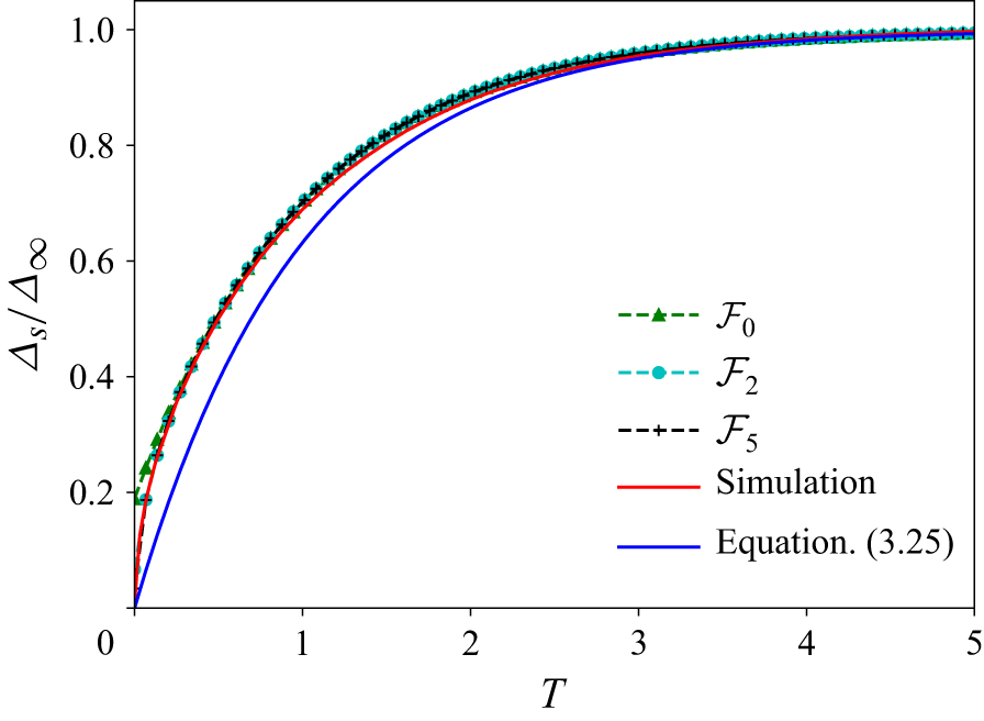
 Δs/Δ∞
 Fn(T)
 n

 H¯(X,T)=H(X,T)/H(0,T)
 β=0.8,r=8,ϱ=1.5×10⁻⁵

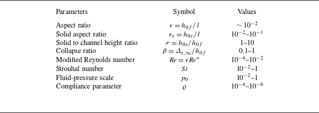

 1−H¯(1,T)
 β
 ϱ
 P(X,T)
 β
 ϱ=1.5×10⁻⁵
 r=8

 Vm(0,T)
 T
 T=0
 Vm(0,0)
 β
 ϱ

 Q(X,T)
 β=0.7 and 0.8
 α=1.1 and 1.3
 ϱ=1.5×10⁻⁵
 r=8

 V¯m(X,T)=Vm(X,T)/Vm(0,T)
 β=0.7 and 0.8
 α=1.1 and 1.3
 ϱ=1.5×10⁻⁵
 r=8

 Q(X,T)
 β=0.7 and 0.8
 α=0.7 and 0.9
 ϱ=1.5×10⁻⁵
 r=8

 V¯m(X,T)=Vm(X,T)/Vm(0,T)
 β=0.7 and 0.8
 α=0.7 and 0.9
 ϱ=1.5×10⁻⁵
 r=8

 ϱ−β−r
 δ=2%

 H¯
 X
 T
 T=0
 T=1
 T=2
 T=3
 T=4
 T=5

 H¯
 X
 T
 β=0.5,r=8,ϱ=4.7×10⁻⁴
 β=0.75,r=6,ϱ=3.5×10⁻⁵

 H(X,T)
 X
 T
 β=0.8,r=8,ϱ=1.5×10⁻⁵

 Open access

