I. INTRODUCTION
Lithium-excess manganese layered oxides, which are commonly described by the chemical formula zLi2MnO3–(1 − z)LiMeO2 (Me = Co, Ni, Mn, etc.), are of great importance as positive electrode materials for rechargeable lithium batteries and can deliver higher capacity (>230 mAh/g) with higher operating voltage (>3.5 V versus Li/Li+ on average).Reference Johnson, Kim, Lefief, Li, Vaughey and Thackeray1 Various stoichiometries with different combinations of lithium manganese oxide (Li2MnO3) and lithium metal oxide [LiMeO2 (Me = Co, Ni, Mn etc.,)] have been studied in the recent past and are considered as potential candidates to replace the commercial lithium cobalt (III) oxide (LiCoO2). These mainly include Li1.2Ni0.2Mn0.6O2 [0.5Li2MnO3·0.5LiNi0.5Mn0.5O2] and Li1.2Ni0.13Co0.13Mn0.54O2 [0.5Li2MnO3·0.5LiNi0.33Mn0.33Co0.33O2].Reference Liu, Wang, Jayan and Manthiram2,Reference Kang, Kempgens, Greenbaum, Kropf, Amine and Thackeray3 The use of the cobalt helps in reducing the electrode polarization. Li2MnO3 is known to be electrochemically inactive because of the presence of Mn in its +4 oxidation state. However charging this material above 4.5 V can apparently electrochemically activate the material due to the extraction of Li and O, which in turn leads to the formation of the manganese dioxide (MnO2) host structure in the compound, which can then reversibly intercalate lithium ions.Reference Lu and Dahn4
Among them, Li1.2Ni0.13Co0.13Mn0.54O2 (LNCMO) has been extensively studied as a promising cathode material for Li-ion batteries, because it delivered an anomalously high discharge capacity of more than 300 mAh/g (at a current rate of 15.7 mA/g and 60 °C), which is slightly larger than the estimated value based on the solid-state redox of the transition metal ions.Reference Liu, Jayan and Manthiram5 However, there are several problems such as low initial efficiency during the first charge-discharge process and the poor rate capability, which should be overcome so as to put it into application as soon as possible. On the other hand, to obtain highly crystalline Li1.2Ni0.13Co0.13Mn0.54O2 with excellent electrochemical performance, high sintering temperature (approximately 850–1500 °C) is essential during the synthesis process, which tends to produce large grains that may increase the diffusion pathway lengths.Reference Yabuuchi, Yoshii, Myung, Nakai and Komaba6
One possible solution to this dilemma would be the use of large colloid templates, resulting in according large and mechanically stable pores on the walls. Such materials were already described as three-dimensional ordered macroporous (3DOM) materials, utilizing poly (styrene) (PS) and poly (methyl methacrylate) (PMMA) colloidal crystal templating routes for macroporous inorganic oxides, metals and alloys, and metal phosphates.Reference Yang, Zhao, Margolese, Chmelka and Stucky7–Reference Long, Sassin, Fischer and Rolison10 Especially, when these porous materials are used as electrode materials for high-rate lithium ion batteries, it would minimize diffusion pathway lengths and increase active surface for lithium insertion due to their nanometer-sized features and high surface areas.Reference Wang, Kiesel and Stein11–Reference Lu, Schmidt, Spliethoff and Schüth13 However, to the best of our knowledge, there are no reports on porous solid solution cathode materials, possessing three-dimensional macroporous structure with pores in the range below 300 nm. In this article, we chose PMMA colloid particles as templates, which are advantageous over PS templates because of better wettability with polar solvents (such as H2O and alcohol), milder removal conditions, and also they introduce fewer structural defects.Reference Yan, Blanford, Lytle, Carter, Smyrl and Stein14 As stated in a previous report, Doherty’s group had prepared macroporous lithium iron (II) phosphate (LiFePO4), also referred to as lithium ferrophosphate or LFP, using PMMA colloidal crystal and surfactant templates, which shows that the rate performance of macroporous LiFePO4 is better than that of bulk LiFePO4, confirming the importance of a high surface area for improving rate capability.Reference Doherty, Caruso, Smarsly and Drummond15,Reference Doherty, Caruso and Drummond16
In this study, we first prepared porous Li1.2Ni0.13Co0.13Mn0.54O2 nanoplate by colloidal crystal template. The aim of this study is to synthesize size-controllable PMMA template, which would ensure that highly crystalline Li1.2Ni0.13Co0.13Mn0.54O2 material is formed while maintaining high specific surface area. The structural features of material are characterized by x-ray diffraction (XRD), scanning electron microscopy (SEM) and transmission electron microscopy (TEM). Compared to the bulk material prepared by traditional method, porous Li1.2Ni0.13Co0.13Mn0.54O2 cathode material shows higher specific surface area, higher specific capacity and rate performance.
II. EXPERIMENTAL
The PMMA latex spheres were synthesized through emulsion polymerization of methyl methacrylate (MMA) based on a technique described in the literature.Reference Wang, Liu, Liu, Qiao, Lu, Munroe and Ahn17 The MMA monomer (17 g) was distilled in deionized water (180 mL) in the presence of sodium dodecyl sulfate (0.01 g). The MMA solution was heated to 70 °C before the addition of initiator. During heating, the solution was stirred and purged with nitrogen gas. When the temperature fluctuation was less than 1 °C, 0.104 g of the initiator, potassium peroxodisulfate, dissolved in 10 mL of deionized water were added to the above solution. The solution turned milky white as MMA began to polymerize, forming a colloidal suspension. The polymerization occurred at 70 °C under nitrogen for 4 h. When the reaction had finished, the milky solution was centrifuged (8000 r/min) for 5 min to remove large agglomerates from the monodisperse sphere suspension. Subsequently, the monodisperse sphere suspension was poured into a Petri dish and dried under ambient conditions to evaporate slowly overnight. Then opalescent PMMA latex colloidal crystals were obtained after the spheres settled and water was removed.
Porous Li1.2Ni0.13Co0.13Mn0.54O2 (Porous LNCMO) was prepared using the PMMA latex colloidal crystals as template. First, 19.327 g of aqueous manganese (II) nitrate [Mn(NO3)2] (≥50%) was mixed with 10 g of ethanol (≥99.7%) in a 100 mL beaker and stirred for 5 min. 8.688 g of lithium nitrate (LiNO3) (≥98%), 3.780 g of nickel (II) nitrate hexahydrate [Ni(NO3)2·6H2O] (≥98.5%) and 3.783 g of cobalt (II) nitrate hexahydrate [Co(NO3)2·6H2O] (≥99%) were then added and stirred until a clear solution was obtained. Subsequently, the precursor solution was added dropwise over a dish containing dried template so that the precursor solution could be infiltrated in the free voids of the template. The composite material template/inorganic precursor was kept at room temperature for 24 h in a dry atmosphere and heated in air with a 0.5 °C/min rate to a temperature of 350 °C and was kept at this temperature for 4 h, and then heated with a 5 °C/min rate to a temperature of 900 °C and kept for 10 h. During thermal treatment the template was eliminated, and porous Li1.2Ni0.13Co0.13Mn0.54O2 (denoted as Porous-LNCMO) was obtained.
For comparison, a mixed aqueous solution of 8.688 g LiNO3 (≥98%), 3.780 g Ni(NO3)2·6H2O (≥98.5%), 3.783 g Co(NO3)2 6H2O (≥99%) and 19.327 g aqueous Mn(NO3)2 (≥50%) were homogeneously mixed, then the precursor was filtered, dried and calcined under the same conditions as above, and bulk Li1.2Ni0.13Co0.13Mn0.54O2 (denoted as Bulk-LNCMO) was obtained.
The morphology and microstructure of obtained products were characterized by x-ray power diffraction (XRD, Rigaku D/max-2500, Rigaku Co., Japan, Cu Kα radiation, λ = 1.50405 Å), field-emission scanning electron microscopy (FESEM, JSM-6700F, JEOL Ltd., Japan) and transmission electron microscopy (TEM, JEOL 200CX and JEOL JSM-2010F, JEOL Ltd., Japan) in the Instrumental Analysis and Research Center, Shanghai University. The specific surface area was obtained from N2 adsorption-desorption analysis conducted at 77 K on a Quadrasorb SI. The specific surface area was calculated by the Brunauer-Emmett-Teller (BET) method.
The electrochemical test of the obtained composites was carried out in 2016 coin-type cells. The working electrodes were prepared by mixing 85 wt% active materials, 10 wt% acetylene black and 5 wt% polytetrafluoroethylene (PTFE). The lithium metal foil was used as the anode while the electrolyte was a solution of 1 M lithium hexafluorophosphate (LiPF6) in dimethyl carbonate (DMC) and ethylene carbonate (EC) (1:1 by weight). The coin-cells were assembled in an argon-filled glove box and tested on a LAND CT2001A cell test system with galvanostatic charge and discharge in the voltage range of 2.0–4.8 V under different current density at room temperature.
III. RESULTS AND DISCUSSIONS
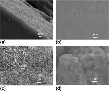
Figures 1(a) and 1(b) shows FESEM images of the colloidal crystal of PMMA and well-defined ordered closed-packed arrays in three dimensions (3D). The diameter of the PMMA latex spheres is about 250 nm with narrow distribution. The morphology of latex spheres is well defined, possessing a close-packed arrangement over a range of hundreds of micrometers. This provides a good scaffold into which the Li1.2Ni0.13Co0.13Mn0.54O2 precursor could infiltrate. For high-rate batteries, crystalline cathode materials are preferred to provide fast ionic transport. However, in surfactant-templated syntheses, extensive crystallization is usually deleterious to the mesostructure. Therefore, a moderate sintering temperature and proper synthesis condition are critical for keeping a structure with interconnected pores and thin crystalline walls of active material.
FESEM images of (a, b) the colloidal crystal formed using PMMA beads, (c) porous Li1.2Ni0.13Co0.13Mn0.54O2 (inset: magnified nanoplates) and (d) bulk Li1.2Ni0.13Co0.13Mn0.54O2.

Combined with details from previous literature relating to simultaneous thermal gravimetric analysis along with differential scanning calorimetry (TG-DSC), we can conclude that the surfactant and PMMA decomposed at between 250 and 300 °C in air, with endothermic DSC peaks at about 294 °C,Reference Vu and Stein18 whereas the total decomposition temperature of Mn(NO3)2, Ni(NO3)2·6H2O, and Co(NO3)2·6H2O are about 200, 301, and 242 °C, respectively.Reference Yuvaraj, Fan-Yuan, Tsong-Huei and Chuin-Tih19 Removal of the surfactant and PMMA templates before this step would result in the loss of the supporting and confining scaffold for the inorganic phase, rendering grain growth less controllable during the crystallization process. It would therefore seem beneficial to treat the precursor first at temperatures below 350 °C to harden the inorganic skeleton, while it is still supported by the organic templates, and only then to treat the sample at higher temperatures (approximately 900 °C) to remove the templates and to induce further crystallization of the active Li1.2Ni0.13Co0.13Mn0.54O2 phase.
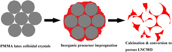
Figure 1(c) shows a FESEM image of porous Li1.2Ni0.13Co0.13Mn0.54O2 prepared using a colloidal crystal template, from which it is clearly visible that the cathode materials are composed of many nanoplates with an average thickness of about 30 nm, and these nanoplates (500–600 nm) interweave together forming an open porous structure. The morphology is different from the oxides [such as cerium (IV) oxide (CeO2), titanium dioxide (TiO2)] and LiFePO4 synthesized via PMMA templates techniques.Reference Vu and Stein18,Reference Holland, Blanford, Do and Stein20,Reference Wang, Sel, Djerdj and Smarsly21 It can be attributed to three reasons as follows. First, these transmetal nitrates have nearly equal decomposition temperature to that of PMMA, which means that the inorganic phase formation and removal of PMMA template almost occurred simultaneously; it may result in phenomena similar to those occurring during a Pechini synthesis.Reference Liu, Farrington, Chaput and Dunn22 Therefore, it is difficult to form thin crystalline walls of active material into ordered porous structure except when an appropriate presintering temperature is selected. Second, the heat treatment processes for the sample in inert gas and in air are quite different. Sudden violent gas release accompanied by bursts of strong heat release may be produced if the precursors are decomposed too fast in air. Because of the high porosity and thin wall thickness, the inorganic frameworks are quite fragile. Both the melting and outgassing of templates and thermal shock (i.e., uneven thermal expansion) may break the wall structure. For keeping the structure as ordered as possible, a slow heating rate (e.g., ≤1 °C/min) should be used to ensure a gentle process, especially at the stages when the polymer template gasifies or undergoes combustion.Reference Tonti, Torralvo, Enciso, Sobrados and Sanz23 Finally, the calcinations temperature has great impact on the morphology of the final composite. It is believed that two kinds of shrinkage may occur at high temperature: one is shrinkage of the latex template, which results in the loss of the supporting and confining scaffold for the inorganic phase; the other is the shrinkage of the wall structure as grains grow and aggregate, which may lead to breakup of ordered porous structure and formation of the thin crystalline walls of active material.Reference Yan, Blanford, Holland, Smyrl and Stein24 Herein, by carefully controlling the presintering temperature and the heating rate, porous Li1.2Ni0.13Co0.13Mn0.54O2 consisting of nanoplates are synthesized [as shown in Fig. 1(c)], which are parts of the walls of the ordered porous structure (red circles in the inset). The preparation process of porous Li1.2Ni0.13Co0.13Mn0.54O2 nanoplates by the PMMA latex colloidal crystals templates is illustrated in Fig. 2. The specific surface area of porous Li1.2Ni0.13Co0.13Mn0.54O2 has been found to be 19.0 m2/g by BET test, which is higher than the Li1.2Ni0.13Co0.13Mn0.54O2 prepared by methods of coprecipitation, sol-gel and sucrose combustion.Reference Zheng, Wu and Yang25 Note that the open, interconnected pore system in the 3DOM structure facilitates penetration of an electrolyte, and the large accessible surface of the material can enhance the exchange of Li+ between the electrolyte and the electrode.
Schematic diagram of the synthesis of porous Li1.2Ni0.13Co0.13Mn0.54O2.

Figure 1(d) presents a FESEM image of bulk Li1.2Ni0.13Co0.13Mn0.54O2. Obviously, the crystal faces and edges exist on the samples of Li1.2Ni0.13Co0.13Mn0.54O2, which represent indirect proof of the solid solution’s good crystallinity. Compared with the porous Li1.2Ni0.13Co0.13Mn0.54O2, the bulk material exhibiting larger particle size (1 μm) has a lower specific surface area of 3.2 m2/g. SEM image also shows that the thermally treated sample possesses agglomerated particles, which can be attributed to the fact that the medium can prevent agglomeration of the particles that does not exist between the particles.
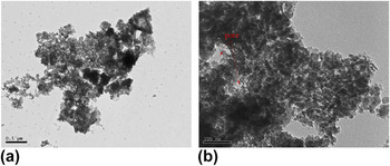
For investigating the morphology and microstructure of porous Li1.2Ni0.13Co0.13Mn0.54O2, we performed TEM observation (Fig. 3) on the sample. In TEM, nanoplates of porous Li1.2Ni0.13Co0.13Mn0.54O2 are consisting of nanoparticles that have a size range of 30 nm and pores are uniformly distributed in the sample, which is consistent with the results of FESEM [Fig. 1(c)]. Therefore, based on FESEM and TEM observation, we can conclude that Li1.2Ni0.13Co0.13Mn0.54O2 prepared using a colloidal crystal template has a porous structure, in which Li1.2Ni0.13Co0.13Mn0.54O2 nanoplates interweave together forming an open porous structure, and the nanoplates are composed of nanoparticles whose size is consistent with thickness of the nanoplates. It would minimize the diffusion pathway lengths and ensure facile infiltration of electrolyte into the pores in the lithium ion cells and increase active surface for lithium insertion.
TEM image of porous Li1.2Ni0.13Co0.13Mn0.54O2.

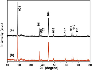
The XRD patterns of porous Li1.2Ni0.13Co0.13Mn0.54O2 and bulk Li1.2Ni0.13Co0.13Mn0.54O2 are shown in Fig. 4. All the diffraction peaks can be indexed to a conventional hexagonal unit cell with space group symmetry of R-3m except for superlattice lines observed around 2θ value 22° corresponding to the ordering of the transition metal ions and Li ions in the transition metal layer of the layered lattice.Reference Lu, Beaulieu, Donaberger, Thomas and Dahn26 A similar trend has been found in the previous reports on the Li2MnO3 system.Reference Johnson, Li, Vaughey, Hackney and Thackeray27,Reference Pasero, McLaren, Souza and West28 The peaks for the two samples are very sharp, indicating good crystallinity of the solid solution materials.
XRD patterns of (a) porous Li1.2Ni0.13Co0.13Mn0.54O2 and (b) bulk Li1.2Ni0.13Co0.13Mn0.54O2.

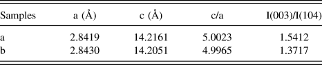
The lattice parameters of two samples are summarized in Table I. As the ionic radii of Li+ (0.76 Å, 3a) and Ni2+ (0.69 Å, 3b) ions are similar, a partial disordering among the 3a and 3b sites is expected and it is called as “cation-mixing.”Reference Chen and Dahn29 The integrated intensity ratios, I(003)/I(104), of both two samples are larger than 1.2, which indicate less cation disordering to deliver good electrochemical performance.Reference Liu, Gao and Ji30 Besides, the parameters c and c/a of porous Li1.2Ni0.13Co0.13Mn0.54O2 are higher than those of bulk Li1.2Ni0.13Co0.13Mn0.54O2, respectively, which demonstrate that porous Li1.2Ni0.13Co0.13Mn0.54O2 has a more desirable layered structure than bulk Li1.2Ni0.13Co0.13Mn0.54O2.Reference Kim, Park and Sun31 These results may be related to the presence of PMMA templates, which will obviously increase the local heat of the system leading to the formation of oxides particles with more organized microstructure during the sintering process.Reference Subramanian, Karki and Rambabu32
Lattice parameters for (a) porous Li1.2Ni0.13Co0.13Mn0.54O2 and (b) bulk Li1.2Ni0.13Co0.13Mn0.54O2.
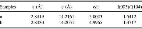
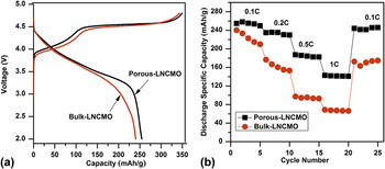
Figure 5(a) shows the initial charge–discharge curves of porous Li1.2Ni0.13Co0.13Mn0.54O2 and bulk Li1.2Ni0.13Co0.13Mn0.54O2 at 0.1C (1C = 250 mA/g) rate in the voltage range of 2.0–4.8 V. The voltage profiles were similar to those presented by Zhao et al.Reference Zhao, Kang, Xue and Shen33 The initial discharge capacity of porous Li1.2Ni0.13Co0.13Mn0.54O2 is 254.8 mAh/g, with the columbic efficiency of about 73.2%. These values are comparable to the materials reported in the previous literature.Reference Zhao, Kang, Xue and Shen33–Reference Hong, Choi, Sim, Lee and Kang35 Whereas the bulk Li1.2Ni0.13Co0.13Mn0.54O2 delivers an initial capacity of 240.3 mAh/g, and the first columbic efficiency is 70.1%. The irreversible capacity of two samples probably results from the oxygen loss from the structure during first cycling and the electrolyte decomposition when the cells are charged above 4.45 V.Reference Lu and Dahn4 The discharge curve of porous Li1.2Ni0.13Co0.13Mn0.54O2 is more flattened than that of bulk Li1.2Ni0.13Co0.13Mn0.54O2, which can increase the energy density of the cell.Reference Yu, Li, Guan, Zheng, Li and Chen34–Reference Sun, Lee, Yoon, Hassoun, Amine and Scrosati36Figure 5(b) shows the cycling performance of porous Li1.2Ni0.13Co0.13Mn0.54O2 and bulk Li1.2Ni0.13Co0.13Mn0.54O2 at different discharge rates in the voltage range of 2.0–4.8 V. The cells were charged at 0.1C rate between 2.0 and 4.8 V before each discharge and then were discharged at 0.1C rate to 1C rate. Clearly, the porous Li1.2Ni0.13Co0.13Mn0.54O2 shows higher discharge capacity than bulk Li1.2Ni0.13Co0.13Mn0.54O2 at all C-rates. Also, the capacity difference between two samples progressively increased with C-rates, and when finally returned to 0.1C, the difference was larger than the 0.1C above. The obtained results thus indicate that porous Li1.2Ni0.13Co0.13Mn0.54O2 cathode material showed higher specific capacity and more excellent cycling stability than the bulk Li1.2Ni0.13Co0.13Mn0.54O2 prepared by the traditional method, which can be attributed to (i) the enhanced structure stability reflected by the higher ratios of integrated intensity I(003)/I(104) and lattice parameters ratio c/a shown in Table I, (ii) the porous structuresReference Vu and Stein18 which ensure facile infiltration of electrolyte into the pores in the lithium ion cells and increase active surface for lithium insertion, (iii) a fast reaction and ionic diffusion kinetics of the nanoplates.Reference Lee, Park, Amine, Bang, Parakash and Sun37,Reference Santhanam and Rambabu38
(a) The initial charge–discharge curves and (b) rate capability of porous Li1.2Ni0.13Co0.13Mn0.54O2 and bulk Li1.2Ni0.13Co0.13Mn0.54O2.

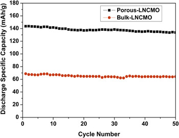
Figure 6 shows the cycling performances of porous Li1.2Ni0.13Co0.13Mn0.54O2 and bulk Li1.2Ni0.13Co0.13Mn0.54O2 at 1C rate in the voltage range of 2.0–4.8 V. The cells were charged at 0.1C rate between 2.0 and 4.8 V before each discharge and then were discharged at 1C rate (The rate of first cycle was 0.1C not shown here). For porous Li1.2Ni0.13Co0.13Mn0.54O2, the discharge capacity decreases to 120.4 mAh/g after 50 cycles with capacity retention of 83.8%. In contrast, the bulk Li1.2Ni0.13Co0.13Mn0.54O2 has a lower but stable discharge capacity at about 68 mAh/g. The decrease in capacity retention of porous Li1.2Ni0.13Co0.13Mn0.54O2 could be ascribed to the side reactions with the electrolyte due to the high specific surface area caused by the porous structure.Reference Liu, Wang, Jayan and Manthiram2 This problem may be solved by the modification of the cathode surface with materials inert against the electrolyte, which will be discussed in our next study.
Cycling performances of porous Li1.2Ni0.13Co0.13Mn0.54O2 and bulk Li1.2Ni0.13Co0.13Mn0.54O2 at 1C rate in the voltage range of 2.0–4.8 V.

IV. CONCLUSIONS
In summary, we successfully prepared porous Li1.2Ni0.13Co0.13Mn0.54O2 cathode material using a colloidal crystal template assembled by the PMMA beads. Compared with the bulk Li1.2Ni0.13Co0.13Mn0.54O2, porous Li1.2Ni0.13Co0.13Mn0.54O2 shows higher specific capacity and excellent rate performance because of the nanoplates and the porous structure. From the results obtained from this work, it can be concluded that porous Li1.2Ni0.13Co0.13Mn0.54O2 prepared using a colloidal crystal template may be a promising candidate for lithium secondary batteries.
ACKNOWLEDGMENTS
This work is supported by the Natural Science Foundation of China (Grant Nos. 11275121 and 21241002), Science and Technology Committee of Shanghai (Grant Nos. 11DZ110020 and 10ZR1411300), and Shanghai Leading Academic Disciplines Project (Grant No. S30109).