1. Introduction
Industrial robots are widely utilized for difficult machining parts due to their larger workspace and flexibility [Reference Rosyid, Stefanini and El-Khasawneh1–Reference Wu, Gao, Zhang and Wang6]. Dual-robot systems are widely utilized across various fields, such as machining [Reference Xiao, Zhao, Guo, Huang and Lin7–Reference Zhao, Tao and Ding9], assembly [Reference Marvel, Bostelman and Falco10–Reference Boschetti, Bottin, Faccio and Minto13], and so on. In a dual-robot system, one robot could be equipped with sensors (e.g., cameras and laser sensors), while the other is equipped with machining end-effectors (e.g., milling tools and grinding tools), which form a measurement-machining dual-robot system. This configuration constitutes a measurement-machining dual-robot system that leverages measurement data to enhance the precision of machining trajectory operations.
However, low trajectory accuracy of the robot limits the quality of surface machining in tasks such as robot milling or grinding. Many researchers have approached this issue from various perspectives, proposing methods to improve the trajectory accuracy of robots. Wu et al. [Reference Wu, Zhang, Wang and Yu14] proposed a method based on iterative learning to design a high-precision feedforward controller, which reduces errors caused by dynamic effects. Maghami et al. [Reference Maghami and Khoshdarregi15] introduced a vision-based robot pose correction technique that enhances the accuracy of robotic drilling operations. Tao et al. [Reference Tao, Chen, Liu, Wan, Wei and Wang16] employed a BLL residual prediction network for error compensation in the robot’s inverse kinematics model, improving model accuracy. Wu et al. [Reference Wu, Li, Wang and Wang17] demonstrated that adding an extra leg can improve the stiffness and natural frequency of a 3-DOF parallel manipulator, enhancing positioning accuracy and motion stability through optimized robot configuration.
To enable the dual-robot system to execute designated tasks with high precision, system calibration is essential. However, the calibration issues associated with dual-robot systems are varied and intricate. Many researchers have conducted studies on this topic. Wang et al. [Reference Wang, Wu, Meng and Ren18] formalized a class of problems in dual-robot systems as AXB = YCZ. This formula has provided a broad foundation for subsequent researchers, inspiring numerous studies in the field. Wu et al. [Reference Wu, Wang, Qi, Wu, Ren and Meng19] proposed a method for simultaneously calibrating multiple sets of relative position and orientation relationships within a dual-robot system, which alleviates the error accumulation caused by traditional asynchronous calibration methods. Sui et al. [Reference Sui and Ding20] solved AXB = YCZ problem by using geometric algebra-based and geometric calculus-based techniques. Qiao et al. [Reference Qiao, Chen, Chen and Xie21] presented a model grounded in the product of exponentials formula, which eliminates the reliance on nominal kinematic parameters. This results in a significant reduction of the robot’s end-effector position error to 0.8563 mm.
Most of the researches on the dual-robot system calibration focus on the global motion range of the robots, which makes it challenging to improve the repeatability and positioning accuracy for a certain machining trajectory. Recently, methods for local calibration within the machining area have sparked extensive research. Many researchers have applied these methods to the calibration of various systems. Nubiola et al. [Reference Nubiola and Bonev22] performed calibration of an ABB IRB 1600 robot within a 0.7 m3 workspace, achieving a positioning error reduction to 0.292 mm. Xu et al. [Reference Xu, Zhu, Zhang, Yan and Ding23] proposed a tool center point-based calibration technique within designated local workspace. This method achieves an impressive accuracy of 0.132 mm. Wang et al. [Reference Wang, Ren, Wang, Liu, Lin, Feng, Zheng and Li24] utilized spherical constraints to calibrate robot end-effectors. This method improved the positioning precision of the robot by 90%. Dehghani et al. [Reference Dehghani, McKenzie, Irani and Ahmadi25] proposed a method for calibrating the kinematic parameters of the robot machining system, which improved the tool path accuracy to 0.15 mm within the specified operational area.
Studies about calibration and trajectory improvement often involve nonlinear optimization problems. Meta-heuristic algorithms demonstrate strong capabilities in escaping local optima and show broad applicability in solving the problems. Many researchers have employed meta-heuristic algorithms in the field of robot calibration and achieved promising results. Chen et al. [Reference Chen, Li, Qiao and Luo26] proved that the Hybrid-of-Evolutionary-Schemes model they introduced could reduce position errors in the industrial robot while maintaining high computational efficiency. Cao et al. [Reference Cao, Nguyen, Tran, Tran and Jeon27] utilized a neural network based on a butterfly and flower pollination algorithm to enhance the accuracy of robot calibration. Chen et al. [Reference Chen and Zhan28] proposed an improved beetle swarm optimization algorithm to enhance the trajectory accuracy of drilling robots. Zhong et al. [Reference Zhong, Hu, Li, Gao, Zeng and Dong29] improved kinematic calibration accuracy of a segmented hydraulic leg system based on an improved whale swarm algorithm. However, none of these researches apply the meta-heuristic algorithm in dual-robot calibration.
This paper proposes a novel method for improving the trajectory accuracy of a dual-robot system through local space calibration and the use of a meta-heuristic algorithm. The objective is to correct the theoretical kinematic model of the robot through dual-robot calibration within a localized region. This aims to enhance the trajectory accuracy of the end-effector within its operational area. Additionally, a meta-heuristic algorithm, Electric Eel Foraging Optimization algorithm (EEFO) [Reference Zhao, Wang, Zhang, Fan, Zhang, Mirjalili, Khodadadi and Cao30], is leveraged to avoid local optima, thereby improving calibration precision. To verify the proposed method, an Archimedean spiral line and a sine surface have been machined by the dual-robot system in this study. The machining results show a significant improvement in trajectory precision.
2. Overview of the measurement-machining robot system
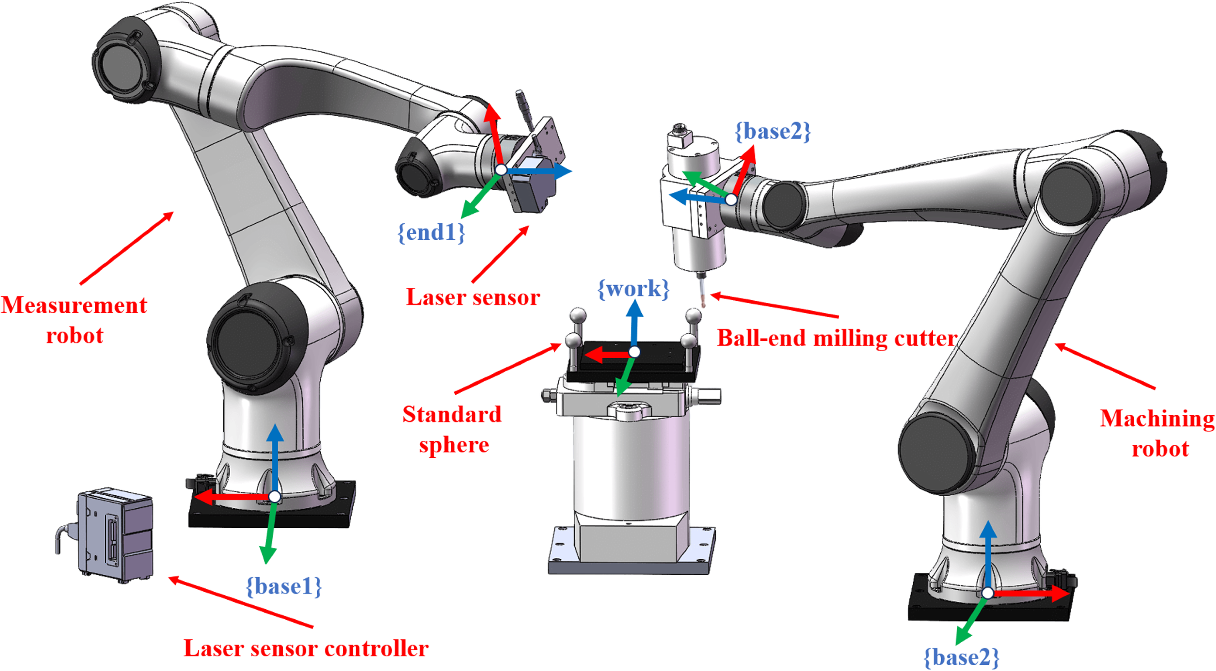
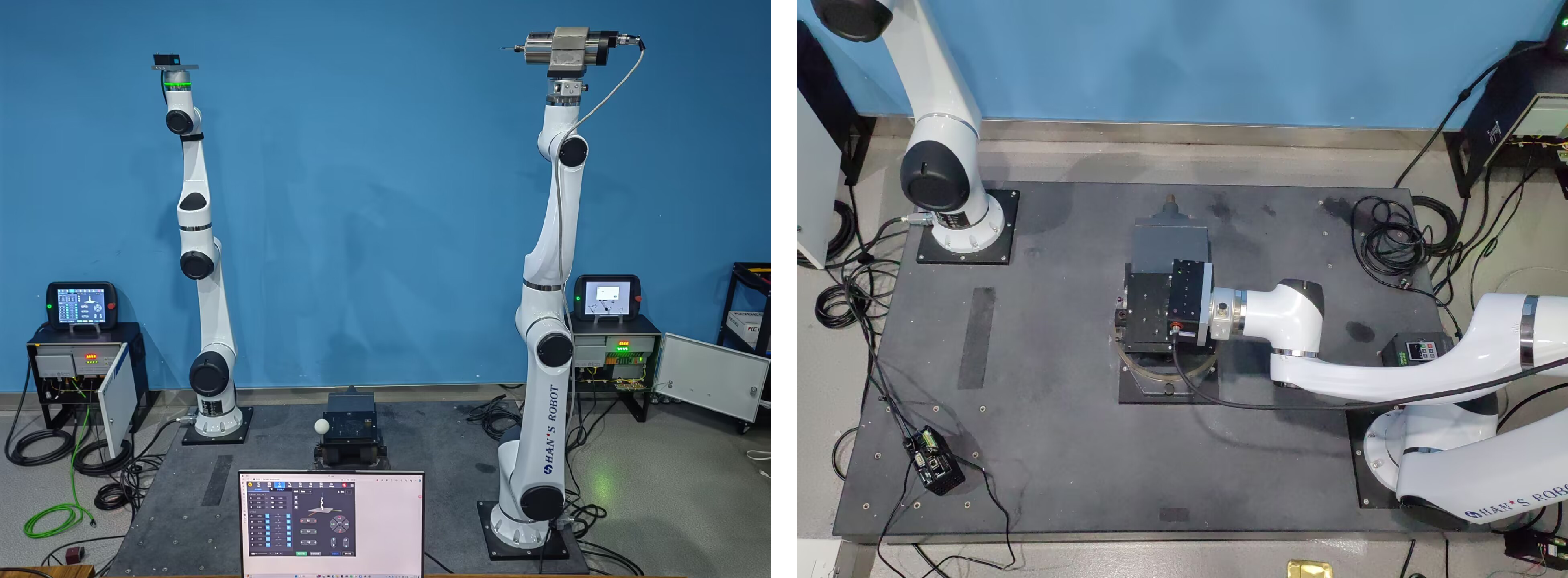
The in situ measurement and machining robot system designed in this study is shown in Fig. 1. The system includes a robot with a high-precision laser sensor mounted at the end, another robot with ball-end milling cutter attached at the end, and a fixture equipped with four standard spheres. Both robots are equipped with six degrees of freedom. This design aims to expand the reachable space of both robots and increase the range of available poses, enabling the system to measure and machine complex parts.
Overview of the experimental platform.

Before machining, it is necessary to establish the kinematic relationship between the two robots and calibrate their kinematic parameters. During the actual machining of specific parts, considering their geometry, fine-tuning of the workpiece coordinate system’s position and pose is often required. Therefore, in each machining task, the measurement robot is used to obtain the position and pose of the workpiece coordinate system, which are transformed to machining side for machining. The workflow of the dual-robot platform proposed in this study is divided into a calibration stage and a machining stage.
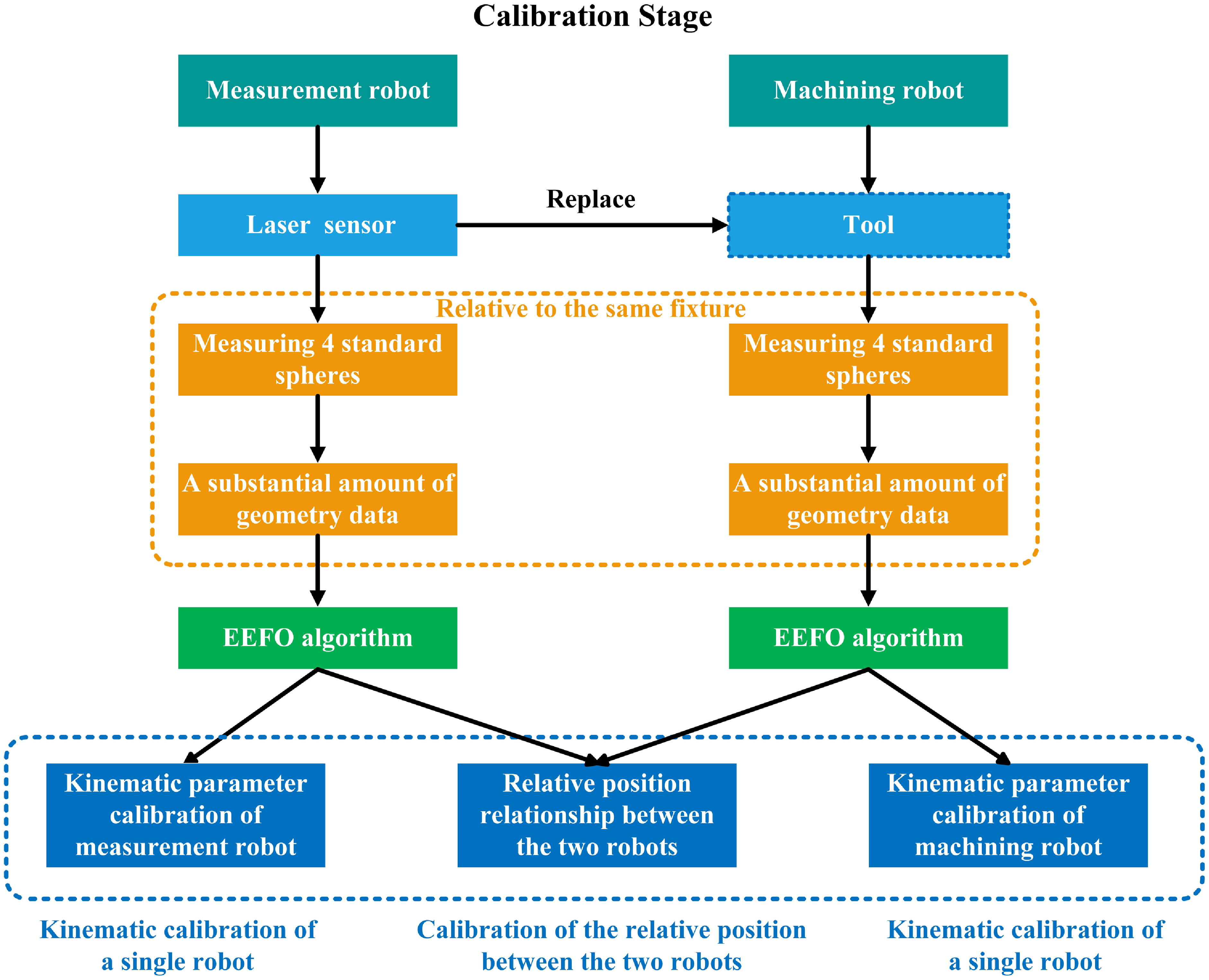
During the calibration stage, both robot end-effectors are equipped with laser sensors to measure four standard spheres within the same workpiece coordinate system, collecting a large amount of geometry data of the standard spheres. Using this data and the EEFO algorithm, the kinematic model for each individual robot is calibrated. Finally, the co-workpiece coordinate system serves as a reference to establish the relationship between the base coordinate systems of the two robots. At this point, both the relationship between the two robots and the kinematic parameters of each robot have been calibrated. The flowchart of the calibration stage is shown in Fig. 2.
The flowchart of the calibration stage.

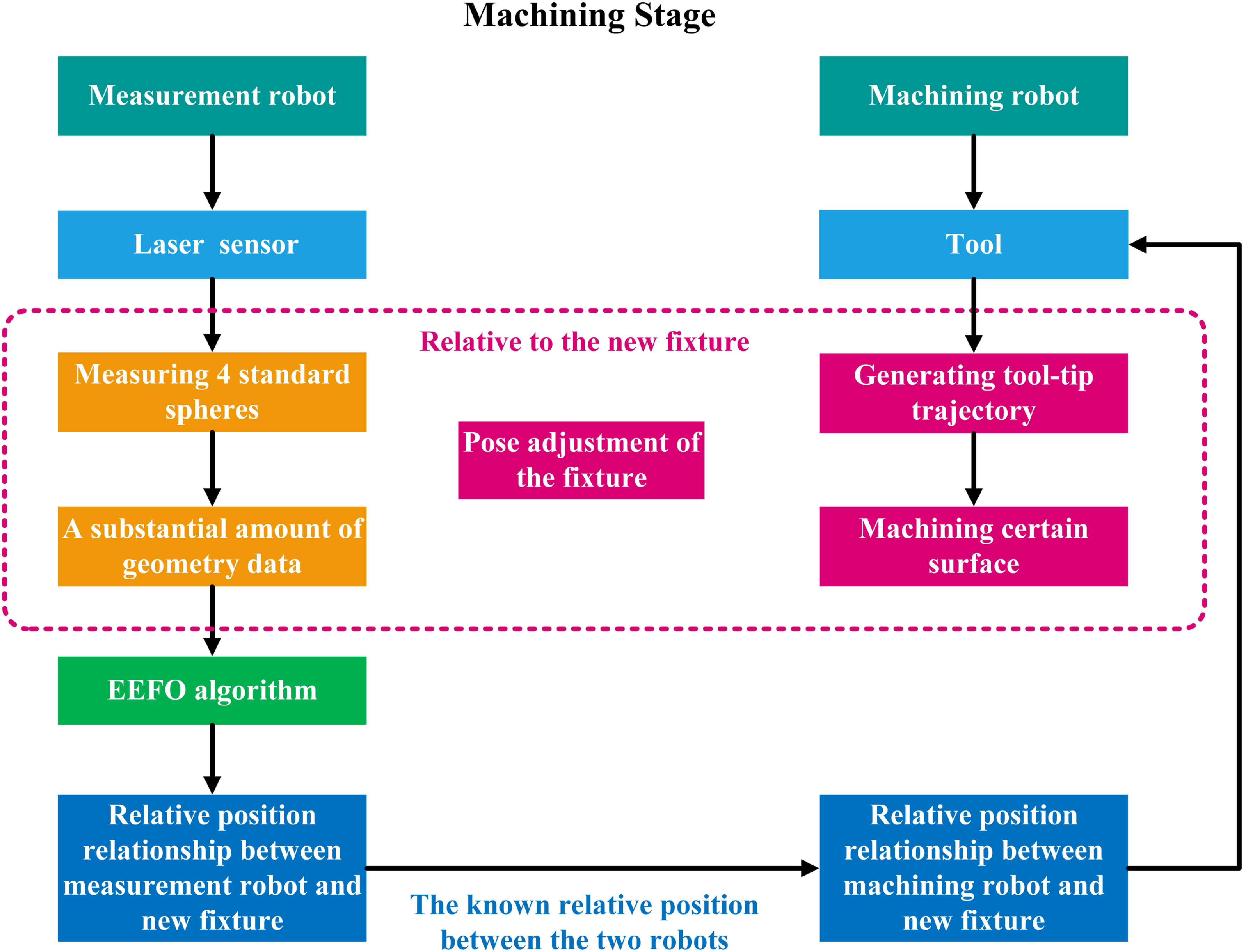
Due to the particularities of the workpieces in each machining instance, adjustments to the position and pose of the workpiece coordinate system are often required. Consequently, the recalibration of its position and pose relative to the machining robot is necessary for each production cycle. In this paper, the measurement robot first measures four standard spheres around the newly adjusted workpiece. The EEFO algorithm is then applied to optimize the kinematic relationship between the new workpiece coordinate system and the two robots. Utilizing the relationship between measurement-machining robot established during the calibration stage, the position and pose of the workpiece coordinate system relative to the base coordinate system of the machining robot are obtained. As a result, the accuracy of the machining robot system is enhanced, and the joint trajectories can be generated based on the calibrated kinematic model of the robot system. The flowchart of the calibration stage is shown in Fig. 3.
The flowchart of the machining stage.

3. The theoretical kinematic model of the measurement-machining robot system
3.1 The theoretical kinematic model of the measurement robot
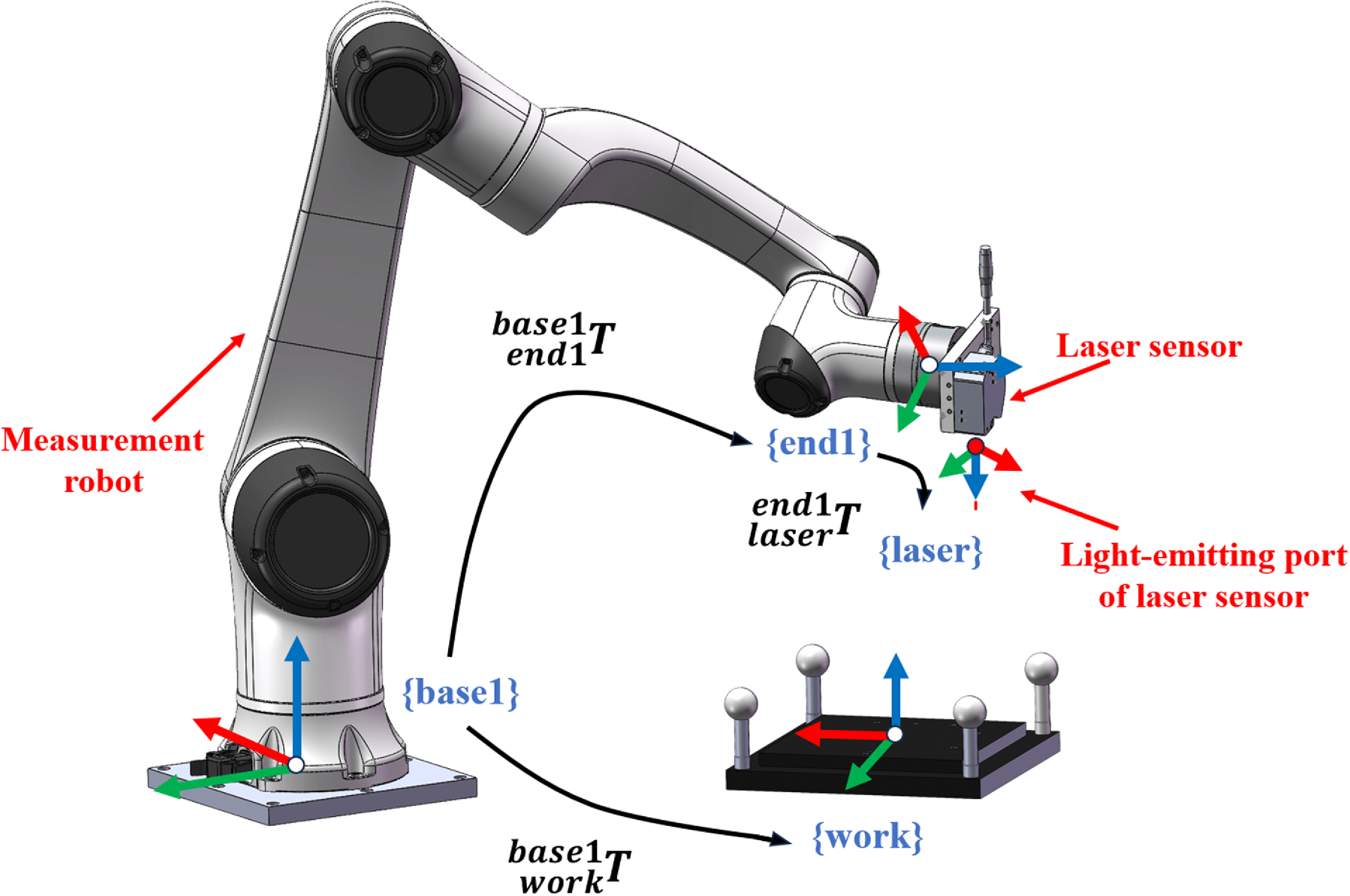
As shown in Fig. 4, the measurement robot is illustrated, where coordinate systems are established for the robot base, flange, laser sensor, and workpiece. In this figure, {base1} is the base coordinate system of the measurement robot. {end1} denotes the flange coordinate system. {laser} refers to the coordinate system of the laser sensor, with its origin at the light-emitting port of the sensor. {work} indicates the workpiece coordinate system, and its origin is at the geometric center of the square fixture.
The theoretical kinematic model of the measurement robot.

 $\,_{work}^{base1}T$
denotes the transformation matrix from {base1} to {work} and is defined as
 \begin{equation}_{work}^{base1}T={}_{work}^{base1}T\_ P\cdot Rot_{z}(R_{z})\cdot Rot_{y}(R_{y})\cdot Rot_{x}(R_{x})\end{equation}
In this equation,
 $\,_{work}^{base1}T\_ P$
is defined as
 \begin{equation}_{work}^{base1}T\_ P=\left[\begin{array}{c@{\quad}c@{\quad}c@{\quad}c} 1 & 0 & 0 & X_{work}\\ 0 & 1 & 0 & Y_{work}\\ 0 & 0 & 1 & Z_{work}\\ 0 & 0 & 0 & 1 \end{array}\right]\end{equation}
 $\,_{work}^{base1}T$
contains three rotation variables
 $R_{x}$
,
 $R_{y}$
,
 $R_{z}$
and three position variables
 $X_{work}$
,
 $Y_{work}$
,
 $Z_{work}$
.
 $\,_{\textit{laser}}^{end1}T$
denotes the homogeneous transformation matrix from {end1} to {laser} and is defined as
 \begin{equation}_{\textit{laser}}^{end1}T={}_{\textit{laser}}^{end1}T\_ P\cdot Rot_{z}(r_{z})\cdot Rot_{y}(r_{y})\cdot Rot_{x}(r_{x})\end{equation}
In this equation,
 $\,_{\textit{laser}}^{end1}T\_ P$
represents the position of the laser sensor’s origin in {end1} and is defined by the following homogeneous matrix:
 \begin{equation}_{\textit{laser}}^{end1}T\_ P=\left[\begin{array}{c@{\quad}c@{\quad}c@{\quad}c} 1 & 0 & 0 & X_{\textit{laser}}\\ 0 & 1 & 0 & Y_{\textit{laser}}\\ 0 & 0 & 1 & Z_{\textit{laser}}\\ 0 & 0 & 0 & 1 \end{array}\right]\end{equation}
 $\,_{\textit{laser}}^{end1}T$
contains three rotation variables
 $r_{x}$
,
 $r_{y}$
,
 $r_{z}$
and three position variables
 $X_{\textit{laser}}$
,
 $Y_{\textit{laser}}$
,
 $Z_{\textit{laser}}$
. Using
 $\,_{\textit{laser}}^{end1}T$
, the homogeneous transformation matrix from {base1} to {laser} can be obtained as
 \begin{equation} _{\textit{laser}}^{base1}T={}_{end1}^{base1}T\cdot {}_{\textit{laser}}^{end1}T\end{equation}
where
 $_{end1}^{base1}{T}{}$
represents the robot forward kinematics model. Using the D-H (Denavit-Hartenberg) parameters provided by the robot manufacturer,
 $_{end1}^{base1}{T}{}$
can be constructed.
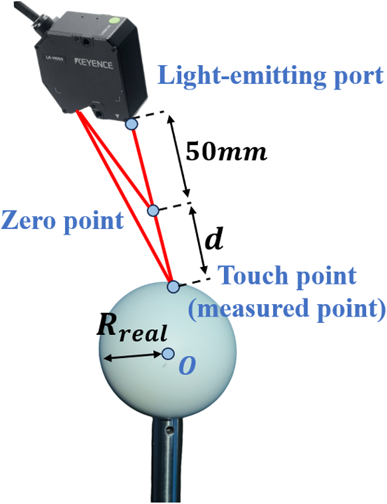
According to the mechanical parameters of the LK-H050 laser sensor, the sensor’s zero point is located 50 mm away from the light-emitting port. If the direction away from the light-emitting port is considered positive, the sensor’s return value
 $d$
represents the distance from the zero point to the intersection of the laser and the contact surface. As illustrated in Fig. 5, the measured point can be described as
The model of the laser sensor and a standard sphere.

 \begin{equation}_{\textit{touch}}^{base1}T={}_{\textit{laser}}^{base1}{T}{}\cdot {}_{\textit{touch}}^{\textit{laser}}{T}{}\_ P\end{equation}
where
 $_{\textit{touch}}^{\textit{laser}}{T}{}\_ P$
represents the position of the measured point in {laser} and can be expressed as
 \begin{equation}_{\textit{touch}}^{\textit{laser}}{T}{}\_ P=\left[\begin{array}{c@{\quad}c@{\quad}c@{\quad}c} 1 & 0 & 0 & 0\\ 0 & 1 & 0 & 0\\ 0 & 0 & 1 & 50+d\\ 0 & 0 & 0 & 1 \end{array}\right]\end{equation}
Thus, the position of the measured point in the base coordinate system of the measurement robot,
 $\,_{\textit{touch}}^{base1}P=[x,y,z]^{T}$
, can be obtained, which is contained within
 $\,_{\textit{touch}}^{base1}T$
.
3.2 The theoretical kinematic model of the machining robot
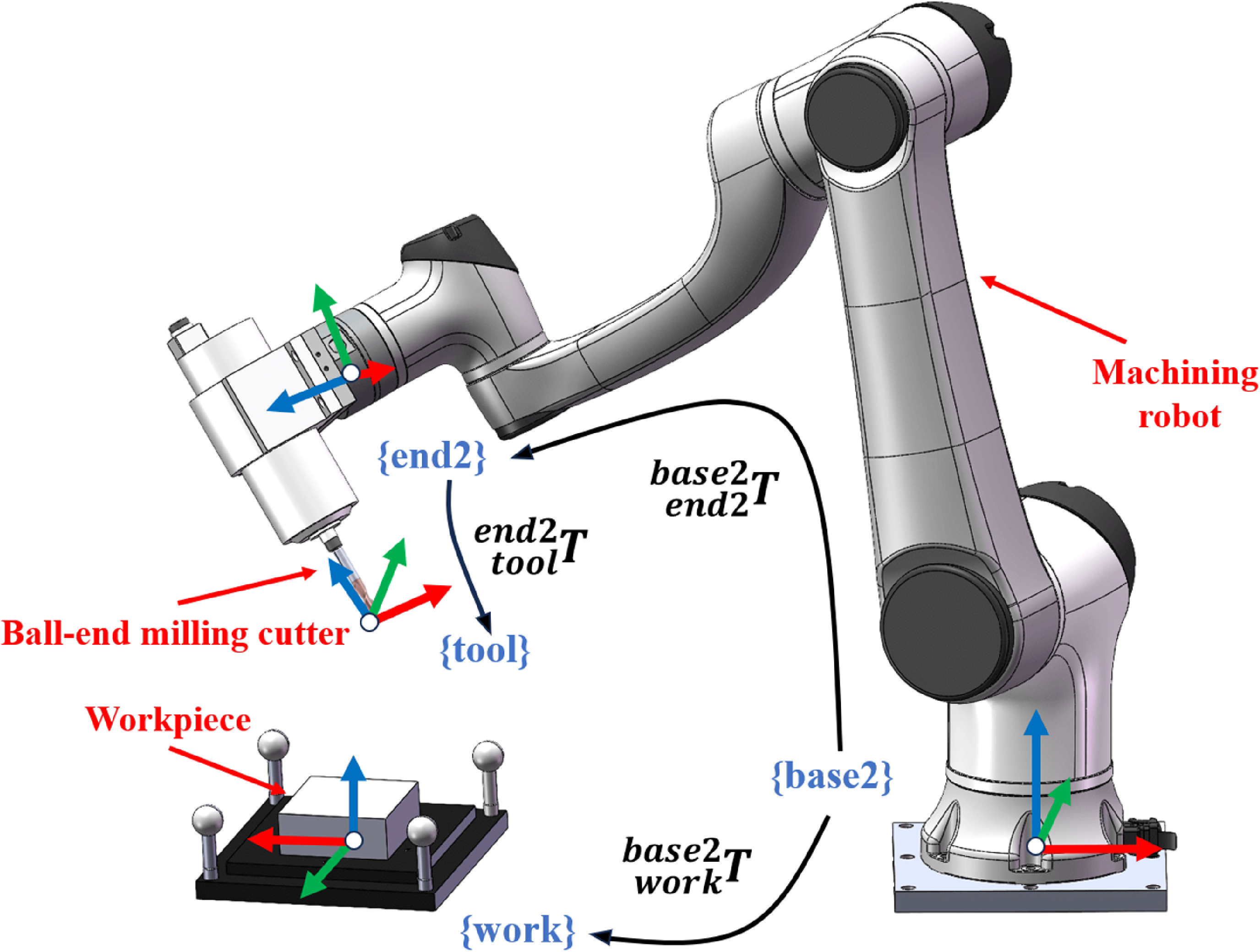
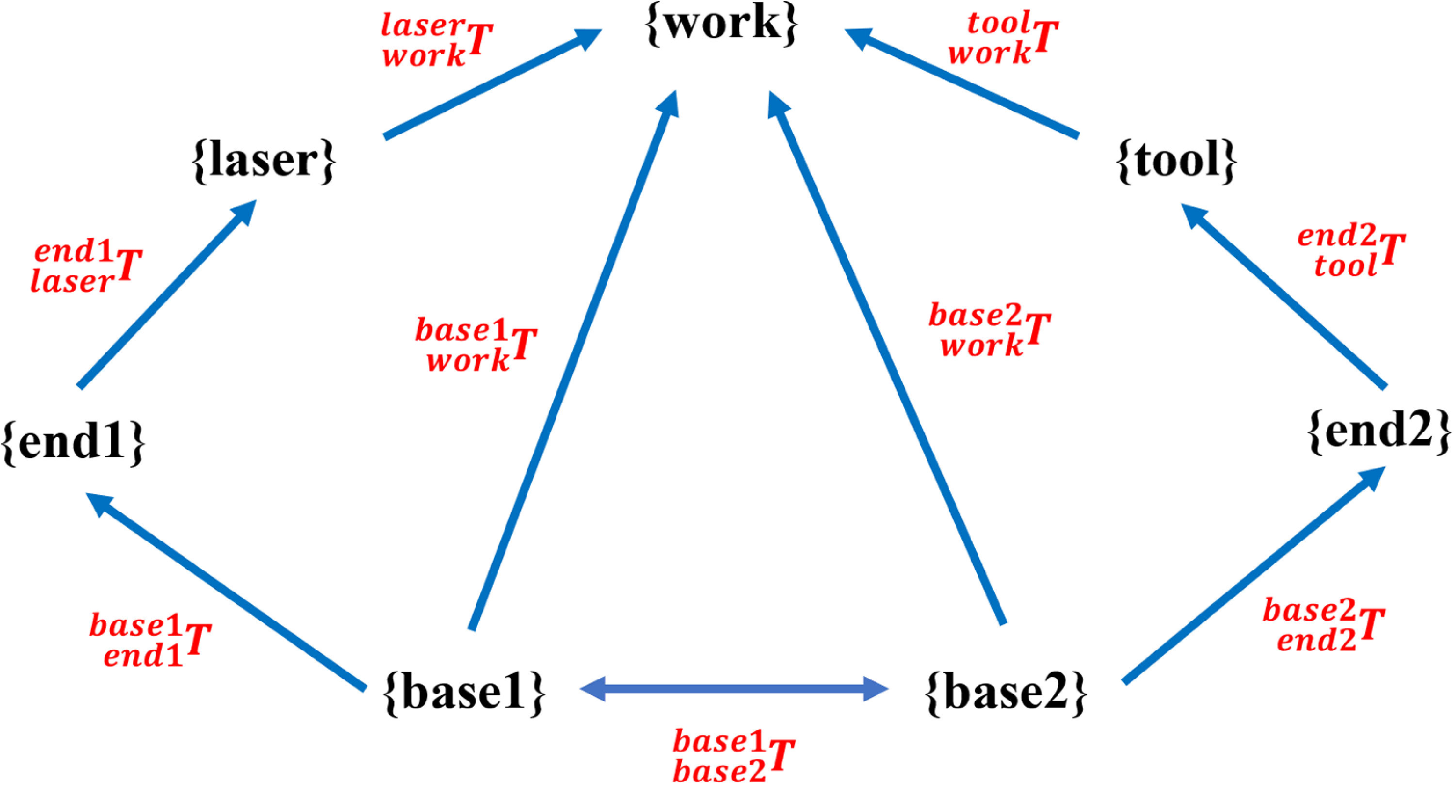
Figure 6 shows the machining robot. Corresponding coordinate systems are established for its base, flange, ball-end milling cutter, and workpiece. {base2} denotes the base coordinate system of the machining robot. {end2} refers to the flange coordinate system of the measurement robot. {tool} represents the coordinate system of the ball-end milling cutter, with its origin located at the tool tip. {work} corresponds to the workpiece coordinate system and matches {work} in Section 3.1. Figure 7 shows the logical relationships between the established coordinate systems.
The theoretical kinematic model of the measurement robot.

The logical relationships between the established coordinate systems.

Since the constructure of the machining robot are identical to that of the measurement robot, the homogeneous transformation matrices between the coordinate systems are familiar. The process for obtaining the target matrices
 $_{work}^{base2}T$
and
 $_{end2}^{base2}T$
is also identical to that of the measurement robot. The matrix
 $_{tool}^{end2}T$
represents the homogeneous transformation matrix of {tool} relative to {end2} and can be expressed as
 \begin{equation}_{tool}^{end2}T={}_{tool}^{end2}T\_ P\cdot Rot_{z}(r\mathrm{'}_{z})\cdot Rot_{y}(r\mathrm{'}_{y})\cdot Rot_{x}(r\mathrm{'}_{x})\end{equation}
In this equation,
 $_{tool}^{end2}{T}{}\_ P$
represents the position of the tool end in {end2}, expressed by the following homogeneous transformation matrix:
 \begin{equation}_{tool}^{end2}T\_ P=\left[\begin{array}{c@{\quad}c@{\quad}c@{\quad}c} 1 & 0 & 0 & X_{tool}\\ 0 & 1 & 0 & Y_{tool}\\ 0 & 0 & 1 & Z_{tool}\\ 0 & 0 & 0 & 0 \end{array}\right]\end{equation}
Equations and involve three rotational variables,
 $r'_{x}$
,
 $r'_{x}$
,
 $r'_{\mathrm{z}}$
and three positional variables,
 $X_{tool}$
,
 $Y_{tool}$
, and
 $Z_{tool}$
. Consequently, the position of the tool tip in {base2} is denoted as
 $_{tool}^{base2}P=[x,y,z]^{T}$
. This position is encapsulated within the matrix
 $_{tool}^{base2}{T}{}$
, which is calculated using the following formula:
 \begin{equation}_{tool}^{base2}{T}{}={}_{end2}^{base2}T\cdot {}_{tool}^{end2}T\end{equation}
3.3 The theoretical kinematic model of the dual-robot system
The schematic diagram illustrating the logical relationships between the established coordinate systems is as follows:
Based on the established kinematic relationships of each robot, it is necessary to obtain the kinematic relationship between the robots, thus forming a dual-robot system. The matrix
 $\,_{base1}^{base2}T$
defines the relationship between the base coordinate systems of the measurement robot and machining robot. Considering that both robots share a common workpiece coordinate system, the matrix
 $\,_{base1}^{base2}T$
can be expressed as
 \begin{equation}_{base1}^{base2}T={}_{work}^{base2}{T}{}\cdot \left(_{work}^{base1}{T}{}\right)^{-1}\end{equation}
 $_{work}^{base1}{T}{}$
and
 $_{work}^{base2}{T}{}$
denote the calibrated homogeneous transformation matrices of the {work} relative to {base1} and {base2}, respectively.
4. Calibration of the dual-robot system and the machining stage
In a dual-robot system, the deviation between the theoretical and actual relative positions of the two robot coordinate systems affects the machining accuracy during the machining stage. Therefore, during the calibration stage, kinematic calibration must be performed separately for the measurement robot and machining robot. By using the shared workpiece coordinate system, the calibrated spatial relationship between the measurement and machining robots can be determined. During the actual machining process, due to the complexity of the workpiece, the position and orientation of the fixture in the machining area often require adjustments. Therefore, during the machining stage, the workpiece coordinate system needs to be re-measured and recalibrated for each machining instance.
4.1 The calibration stage
As both robots are of the same model, the following discussion will focus on the calibration process of the measurement robot. The same method could be applied for optimizing the model of the machining robot.
The homogeneous transformation matrix
 $_{end1}^{base1}T$
is obtained by multiplying six individual transformation matrices. According to the D-H parameter, each transformation matrix
 $_{i}^{i-1}T$
contains four variables (
 $\alpha _{i-1}$
,
 $a_{i-1}$
,
 $d_{i}$
,
 $\theta _{i}$
), which can be represented as
 \begin{equation}_{i}^{i-1}T=Rot_{x}(\alpha _{i-1})\cdot Trans_{x}(a_{i-1})\cdot Rot_{z}(\theta _{i}+q_{i})\cdot Trans_{z}(d_{i})\end{equation}
where
 $q_{i}$
represents the drive joint angle. By adding deviation quantities
 $\Delta \alpha _{i-1}$
,
 $\Delta a_{i-1}$
,
 $\Delta d_{i}$
, and
 $\Delta \theta _{i}$
to their theoretical values, we obtain the error-considered coordinate transformation matrix
 $_{i}^{i-1}T_{e}$
, as expressed in the following equation:
 \begin{equation}_{i}^{i-1}T_{e}=Rot_{x}(\alpha _{i-1}+\Delta \alpha _{i-1})\cdot Trans_{x}(a_{i-1}+\Delta a_{i-1})\cdot Rot_{z}(\theta _{i}+\Delta \theta _{i}+q_{i})\cdot Trans_{z}(d_{i}+\Delta d_{i})\end{equation}
Thus, the overall kinematic model of the robot is represented by the following formula:
 \begin{equation}_{end1}^{base1}{T_{e}}{}={}_{6}^{0}{T_{e}}{}={}_{1}^{0}{T_{e}}{}\cdot {}_{2}^{1}{T_{e}}{}\cdot {}_{3}^{2}{T_{e}}{}\cdot {}_{4}^{3}{T_{e}}{}\cdot {}_{5}^{4}{T_{e}}{}\cdot {}_{6}^{5}{T_{e}}{}\end{equation}
Considering position-pose errors of
 $_{\textit{laser}}^{end1}{T}{}$
, the
 $_{\textit{laser}}^{end1}T_{e}$
is established and is expressed by adding deviation quantities
 $\Delta r_{x}$
,
 $\Delta r_{y}$
,
 $\Delta r_{z}$
,
 $\Delta X_{\textit{laser}}$
,
 $\Delta Y_{\textit{laser}}$
, and
 $\Delta Z_{\textit{laser}}$
as follows:
 \begin{equation}_{\textit{laser}}^{end1}T_{e}={}_{\textit{laser}}^{end1}T\_ P_{e}\cdot Rot_{z}(r_{z}+\Delta r_{z})\cdot Rot_{y}(r_{y}+\Delta r_{y})\cdot Rot_{x}(r_{x}+\Delta r_{x})\end{equation}
where
 $_{\textit{laser}}^{end1}T\_ P_{e}$
can be expressed as
 \begin{equation}_{\textit{laser}}^{end1}T\_ P_{e}=\left[\begin{array}{c@{\quad}c@{\quad}c@{\quad}c} 1 & 0 & 0 & X_{\textit{laser}}+\Delta X_{\textit{laser}}\\ 0 & 1 & 0 & Y_{\textit{laser}}+\Delta Y_{\textit{laser}}\\ 0 & 0 & 1 & Z_{\textit{laser}}+\Delta Z_{\textit{laser}}\\ 0 & 0 & 0 & 1 \end{array}\right]\end{equation}
Considering the deviation quantities, the coordinates of the measurement point in {base1} are given by
 \begin{equation}_{\textit{touch}}^{base1}{T\_ P_{e}}{}={}_{end1}^{base1}{T_{e}}{}\cdot {}_{\textit{laser}}^{end1}{T_{e}}{}\cdot {}_{\textit{touch}}^{\textit{laser}}{T}{}\_ P\end{equation}
 $_{\textit{touch}}^{base1}{T\_ P_{e}}{}$
denotes the homogeneous transformation matrix representing the position of the measured point in {base1}. The coordinate vector of
 $_{\textit{touch}}^{base1}{T\_ P_{e}}{}$
is denoted as
 $_{\textit{touch}}^{base1}{P_{e}}{}=[x,y,z]^{T}$
.
The error-considered transformation matrix
 $_{work}^{base1}T_{e}$
from {base1} to {work} is established by introducing deviation quantities
 $\Delta R_{x}$
,
 $\Delta R_{y}$
,
 $\Delta R_{z}$
,
 $\Delta X_{work}$
,
 $\Delta Y_{work}$
, and
 $\Delta Z_{work}$
into the six variables
 $R_{x}$
,
 $R_{y}$
,
 $R_{z}$
,
 $X_{work}$
,
 $Y_{work}$
, and
 $Z_{work}$
. This results in the error-considered transformation matrix
 $_{work}^{base1}{T_{e}}{}$
:
 \begin{equation}_{work}^{base1}T_{e}={}_{work}^{base1}T\_ P_{e}\cdot Rot_{z}(R_{z}+\Delta R_{z})\cdot Rot_{y}(R_{y}+\Delta R_{y})\cdot Rot_{x}(R_{x}+\Delta R_{x})\end{equation}
In this equation,
 $_{work}^{base1}{T\_ P_{e}}{}$
can be expressed as
 \begin{equation}_{work}^{base1}{T\_ P_{e}}{}=\left[\begin{array}{c@{\quad}c} \begin{array}{c@{\quad}c} 1 & 0\\ 0 & 1 \end{array} & \begin{array}{c@{\quad}c} 0 & X_{work}+\Delta X_{work}\\ 0 & Y_{work}+\Delta Y_{work} \end{array}\\ \begin{array}{c@{\quad}c} 0 & 0\\ 0 & 0 \end{array} & \begin{array}{c@{\quad}c} 1 & Z_{work}+\Delta Z_{work}\\ 0 & 1 \end{array} \end{array}\right]\end{equation}
Due to the high assembly accuracy between the standard sphere and the workpiece fixture, there is no need to introduce deviation quantities in the matrix
 $_{ball}^{work}{T}{}\_ O$
, which represents the coordinates of the standard sphere center in {work}. Thus,
 $_{ball}^{work}{T}{}\_ O$
can be expressed as
 \begin{equation}_{ball}^{work}{T}{}\_ O=\left[\begin{array}{c@{\quad}c@{\quad}c@{\quad}c} 1 & 0 & 0 & X_{ball}\\0 & 1&0 & Y_{ball}\\ 0 & 0 &1 & Z_{ball} \\ 0 & 0 & 0 & 1 \end{array}\right]\end{equation}
Based on the relationship between {work} and {base1}, the homogeneous transformation matrix for the center of the standard sphere relative to {base1} can be obtained:
 \begin{equation}_{ball}^{base1}{T\_ O_{e}}{}={}_{work}^{base1}{T_{e}}{}\cdot {}_{ball}^{work}{T}{}\_ O\end{equation}
 $_{ball}^{base1}{T\_ O_{e}}{}$
denotes the homogeneous transformation matrix representing the position of the sphere center in {base1}. The coordinate vector of
 $_{ball}^{base1}{T\_ O_{e}}{}$
is denoted as
 $_{ball}^{base1}{O_{e}}{}=[x,y,z]^{T}$
.
Therefore, in {base1}, the coordinates of the measured point (i.e., the contact point on the sphere surface where the laser line intersects)
 $_{\textit{touch}}^{base1}{P_{e}}{}$
and the position coordinates of the sphere center
 $_{ball}^{base1}{O_{e}}{}$
are obtained. The distance between the measured point and the sphere center is denoted as
 $R_{\textit{measured}}$
, which can be expressed as
 \begin{equation}R_{\textit{measured}}=\left\| _{\textit{touch}}^{base1}{P_{e}}{}- _{ball}^{base1}{O_{e}}{}\right\|\end{equation}
 $R_{\textit{measured}}$
represents the actual value of the radius measured by measurement robot and
 $R_{real}$
represents the real value of the radius of the standard spheres provided by manufacturer. Theoretically,
 $R_{\textit{measured}}$
and
 $R_{real}$
should be equal. However, due to deviations in the kinematic model of the robot,
 $R_{\textit{measured}}$
may not match
 $R_{real}$
. Thus, the deviation between
 $R_{\textit{measured}}$
and
 $R_{real}$
can be used as an optimization target to adjust the constructed error-considered kinematic model. When the difference between
 $R_{\textit{measured}}$
and
 $R_{real}$
is minimized, the accuracy of the corresponding 36 deviation quantities is improved. The specific procedure is as follows:
In this study,
 $n$
sets of measurement data can be obtained by measuring the standard spheres, with each set containing values for 6 robot joint angles and
 $d$
. For each set of data, a deviation function
 $f_{i}(i\in [1,n],i\in N)$
can be derived based on 36 decision variables, expressed as follows:
 \begin{equation}f_{i}=({R_{i,\textit{measured}}}-{R_{real}})^{2}\end{equation}
 $R_{i,\textit{measured}}$
represents the radius value calculated based on the
 $i$
th dataset. The objective function
 $G$
can be expressed as
 \begin{equation}G=\frac{1}{n}\sum _{i=1}^{n}f_{i}\end{equation}
The final nonlinear optimization problem can be expressed as
 \begin{equation}minG(\boldsymbol{x});\,s.t.\begin{cases} x_{i,\min}\leq x_{i}\leq x_{i,\max}\\ i=1,2,3,\ldots, 36 \end{cases}\end{equation}
In the formula above,
 $\boldsymbol{x}=[{x_{1}},{x_{2}},\ldots, {x_{36}}]^{T}\in R^{36}$
represents decision variables, which are four deviation quantities (
 $\Delta \alpha _{i-1}$
,
 $\Delta a_{i-1}$
,
 $\Delta d_{i}$
,
 $\Delta \theta _{i}$
) for each joint of the robot, six deviation quantities (
 $\Delta r_{x}$
,
 $\Delta r_{y}$
,
 $\Delta r_{z}$
,
 $\Delta X_{\textit{laser}}$
,
 $\Delta Y_{\textit{laser}}$
,
 $\Delta Z_{\textit{laser}}$
) for the position and pose of the laser sensor coordinate system, and another six deviation quantities (
 $\Delta R_{x}$
,
 $\Delta R_{y}$
,
 $\Delta R_{z}$
,
 $\Delta X_{work}$
,
 $\Delta Y_{work}$
,
 $\Delta Z_{work}$
) for the position and pose of the workpiece coordinate system.
 $x_{i,min}$
and
 $x_{i,max}$
denote the lower and upper bounds of
 $x_{i}$
, respectively. These bounds can be assigned appropriate values based on theoretical estimates of the error.
The optimization problem involves 36 variables, resulting in a high-dimensional optimization problem that requires an appropriate meta-heuristic algorithm to effectively avoid local optima. In this paper, the EEFO algorithm [Reference Zhao, Wang, Zhang, Fan, Zhang, Mirjalili, Khodadadi and Cao30] has been selected for this optimization. The EEFO algorithm is a nature-inspired swarm intelligence optimization technique based on the collective foraging behavior of electric eels. By clustering and driving prey into a “bait ball” for a high-pressure attack, eels optimize their hunting efficiency. This strategy inspires the development of the EEFO algorithm to enhance optimization performance. In this study, the algorithm will search within this range to find the vector
 $\boldsymbol{x}$
that minimizes
 $G$
.
4.2 The machining stage
In machining stage, the workpiece coordinate system needs to be adjusted for each specific machining instance. Therefore, in each machining instance, the measurement robot is employed to measure the four standard spheres around the workpiece and obtain the homogeneous transformation matrix
 $_{\mathit{work}\mathit{'}}^{base1}{T}{}$
. Using
 $_{base1}^{base2}{T}{}$
obtained in the calibration stage,
 $_{\mathit{work}\mathit{'}}^{base2}{T}{}$
can be derived.
Since the kinematic parameters of the measurement robot have already been calibrated during the calibration stage, constructing the objective function
 $H$
only requires introducing six deviation quantities (
 $\Delta R_{x'}$
,
 $\Delta R_{y'}$
,
 $\Delta R_{z'}$
,
 $\Delta X_{\mathit{work}\mathit{'}}$
,
 $\Delta Y_{\mathit{work}\mathit{'}}$
, and
 $\Delta Z_{\mathit{work}\mathit{'}}$
) for the position and pose of the adjusted workpiece coordinate system. The modeling approach for the objective function is consistent with Section 4.1. The objective function
 $H$
can be expressed as
 \begin{equation}H=\frac{1}{n}\sum _{i=1}^{n}f_{i}\end{equation}
The final nonlinear optimization problem can be expressed as
 \begin{equation}minH(\boldsymbol{x});\,s.t.\begin{cases} x_{i,\min}\leq x_{i}\leq x_{i,\max}\\ i=1,2,3,4,5,6 \end{cases}\end{equation}
By applying the EEFO algorithm, the six deviation quantities can be resolved, yielding the transformation matrix
 $_{\mathit{work}\mathit{'}}^{base1}{T}{}$
. Subsequently,
 $_{\mathit{work}\mathit{'}}^{base2}{T}{}$
is derived using the following equation:
 \begin{equation}_{\textit{work}\mathrm{'}}^{base2}{T}{}={}_{base1}^{base2}{T}{}\cdot {}_{\textit{work}\mathrm{'}}^{base1}{T}{}\end{equation}
By using Eq. (28), the surface machining trajectory in work space can be transformed into the machining robot base system to perform high-precision machining. If another surface part needs to be machined, it is only necessary to repeat the steps in this section to obtain the new fixture position.
5. Experiments and results
5.1 Verification of measurement experiments
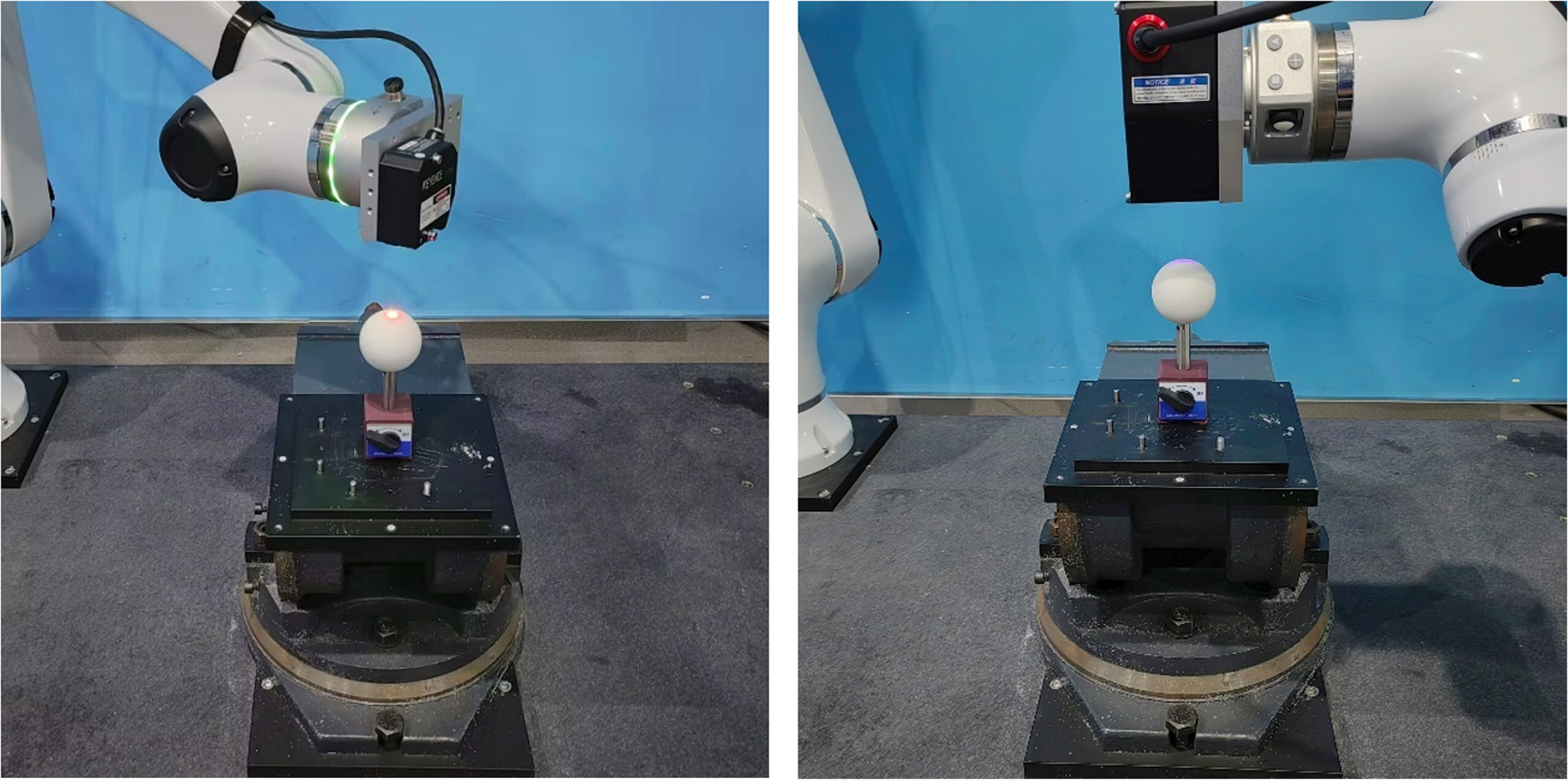
The constructed dual-robot system for measurement and machining is illustrated in Fig. 8. By using the proposed method, an objective function as shown in Eq. (24) is formulated, optimizing structural parameters of the measurement-machining system.
The dual-robot system and the calibration process.

By employing the optimization method proposed in this study, the value of the objective function
 $G$
for the measurement robot is reduced to 1.250, resulting in a minimized sphere radius deviation of 0.039 mm. Similarly, the value of the objective function
 $G$
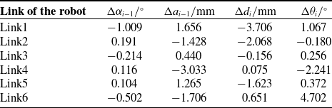
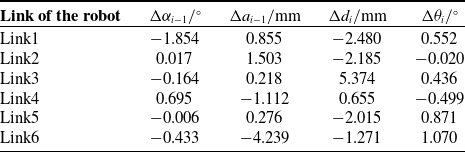
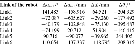
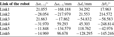
for the machining robot is reduced to 4.025, resulting in a minimized sphere radius deviation of 0.069 mm. Tables I and II list the optimization results of kinematic parameters deviation for measurement robot and machining robot. Tables III and IV list the optimization results of laser sensor coordinate system deviation and workpiece coordinate system deviation for each robot.
EEFO-optimized results of kinematic parameters deviation for measurement robot.

EEFO-optimized results of kinematic parameters deviation for machining robot.

EEFO-optimized results of laser sensor coordinate system deviation.

EEFO-optimized results of workpiece coordinate system deviation.

It should be noted that these parameters are specifically designed to optimize accuracy within a localized region. As the robot’s end-effector moves further away from the workpiece coordinate system, the positioning error may increase. However, this characteristic is advantageous, as these parameters are not intended to reflect the true structural configuration of the robot. Instead, they function as compensation parameters tailored to reduce errors within the specific local space where machining occurs. Since the machining trajectory is confined to a local area, focusing on enhancing local accuracy is far more meaningful than striving for global precision. This approach ensures higher accuracy and efficiency in machining applications, where localized accuracy directly impacts the quality of the machining.
5.2 Calibration accuracy verification experiment
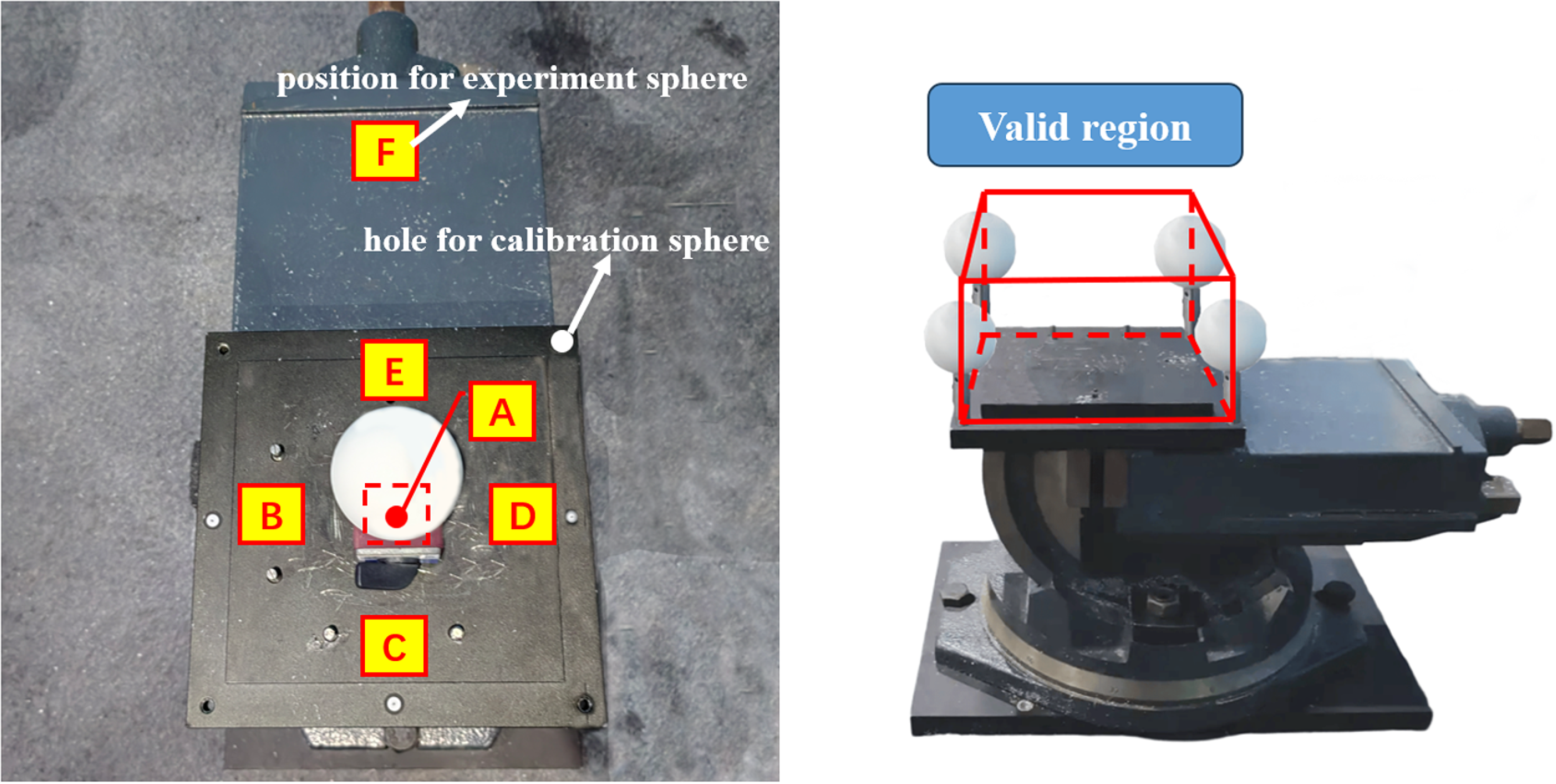
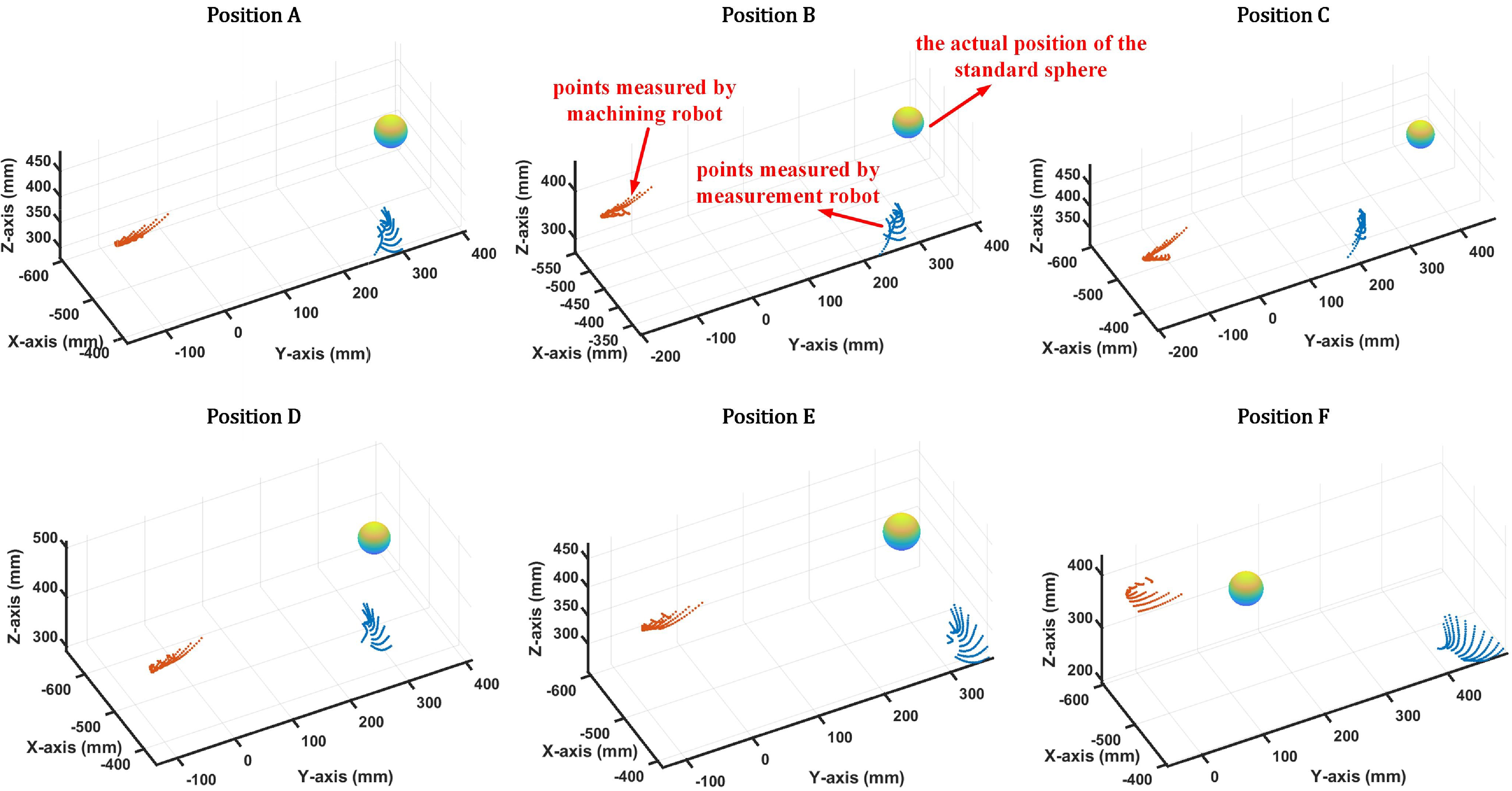
To validate the calibration accuracy of the dual-robot system, measurements and analyses of the standard spheres are conducted both within and outside the valid region. Five positions (Position A∼E) are set within the calibration area for placing the standard spheres, with an additional position (Position F) set outside the effective calibration area. The placement of the standard spheres is shown in Fig. 9.
Settings of test positions.

During the experiment, the measurement robot scans the standard spheres to capture a considerable number of points. Using the calibrated forward kinematics model of the measurement robot, the positions of the measured points in {base1} are obtained, and the position of the sphere center
 $_{ball}^{base1}{O}{}$
can be calculated using a fitting algorithm. Then, the position of the sphere center in {base2}
 $_{ball}^{base2}{O_{cnv}}{}=[x,y,z]^{T}$
can be converted from
 $_{ball}^{base1}{O}{}$
:
 \begin{equation}_{ball}^{base2}{O_{cnv}}{}={}_{base1}^{base2}{T}{}\cdot {}_{ball}^{base1}{O}{}\end{equation}
A laser sensor is mounted on the machining robot to measure the same sphere, thereby directly obtaining the position data
 $_{\textit{touch}}^{base2}{P_{i}}{}$
of the standard sphere in {base2}. Theoretically, the distance
 $\| _{\textit{touch}}^{base2}{P_{i}}{}- _{ball}^{base2}{O_{cnv}}{}\|$
between the measured point and the sphere center should equal the actual radius
 $R_{real}$
. However, due to the deviations in the kinematic model, a discrepancy exists between this distance and
 $R_{real}$
, which reflects the positioning accuracy error. The error at each point can be calculated by the following formula:
 \begin{equation}\delta _{i}=\left| \left\| _{\textit{touch}}^{base2}{P_{i}}{}- _{ball}^{base2}{O_{cnv}}{}\right\| -R_{real}\right| =\left| \left\| _{\textit{touch}}^{base2}{P_{i}}{}- _{base1}^{base2}{T}{}\cdot {}_{ball}^{base1}{O}{}\right\| -R_{real}\right|\end{equation}
 $\delta _{i}$
represents the localization error of the
 $i$
th sampling point. In this experiment, each sphere is sampled at 210 points, thus
 $i\in [1,210], i\in Z$
.
 $_{\textit{touch}}^{base2}{P_{i}}{}$
represents the coordinates of each sampling point in {base2}. Figure 10 shows the procedure of the calibration accuracy verification experiment.
The procedure of the calibration accuracy verification experiment.

Since the calculation of
 $\delta _{i}$
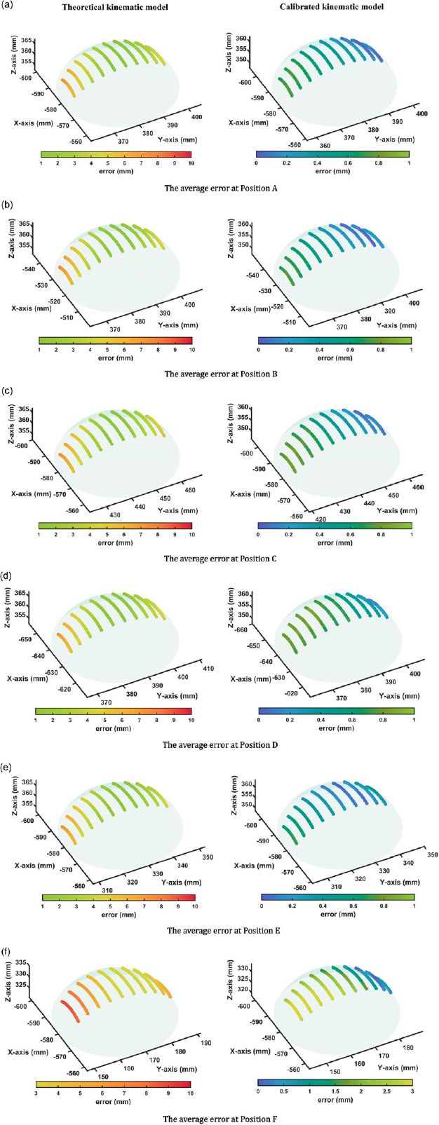
requires the kinematic model of both robots, using different kinematic models will yield different error values. In this study, both the theoretical and calibrated kinematic models are used in Eq. 30 for comparison. The average error values for the measurements at six different positions (Position A∼F) are shown in Fig. 11. Table V lists the average positioning error of the six positions, and Table VI lists the maximal positioning error of the six positions.
Comparison of positioning errors of six test positions.

The average positioning error of the six positions.

The maximal positioning error of the six positions.

From Tables V, VI, and Fig. 11, it can be summarized that the deviation values obtained using the theoretical kinematic model are significantly higher than those using the calibrated kinematic model, both for average and maximal deviations, whether inside or outside the region. This result demonstrates the effectiveness of the calibration algorithm in improving accuracy. At the same time, for the standard spheres inside the region (Position A∼E), the average positioning error after calibration is less than 0.7 mm, and the maximal error is less than 1 mm. For the standard spheres outside the region (Position F), the average positioning error after calibration is 1.7689 mm, and the maximal positioning error is 3.5178 mm. This indicates that the calibration algorithm has a far greater improvement effect within the local region than outside.
The tables also present the accuracy improvement ratio for both inside and outside the region,
 $\textit{Ratio}$
in Tables V and VI is defined as
 \begin{equation}\textit{Ratio}=\left| 1-\frac{E_{ca}}{E_{th}}\right| \times 100\mathrm{\% }\end{equation}
where
 $E_{th}$
represents the positioning error calculated with the theoretical kinematic model, and
 $E_{ca}$
represents the positioning error calculated with the calibrated kinematic model. As shown in the tables, the accuracy improvement ratio for positions inside the region is higher than that for positions outside the region. This further confirms that the calibration algorithm effect on accuracy improvement is more significant within the local region than outside it.
5.3 Algorithm comparison experiment
Due to the nonlinear, high-dimensional, and constrained nature of the dual-robot system calibration problem, traditional gradient-based methods are highly sensitive to initial values, where small deviations may lead to overfitting and cause the algorithm to become trapped in a local optimum. Given that meta-heuristic optimization algorithms possess strong global search capabilities and can better handle such problems, this paper adopts the EEFO algorithm to avoid overfitting and enhance the calibration accuracy. To validate its effectiveness and necessity, this section employs a commonly used gradient-based method, the sequential quadratic programming algorithm (SQP), for calibrating the dual-robot system, and compares the results with those obtained using the EEFO algorithm in Sections 5.1 and 5.2. The relevant results are listed in Tables VII–X.
SQP-optimized results of kinematic parameters deviation for measurement robot.

SQP-optimized results of kinematic parameters deviation for machining robot.

SQP-optimized results of laser sensor coordinate system deviation.

SQP-optimized results of workpiece coordinate system deviation.

By employing the SQP algorithm, the value of the objective function
 $G$
for the measurement robot is reduced to 58691.815 (EEFO: 1.250), which means the minimized sphere radius deviation is 8.359 mm (EEFO: 0.039 mm). Similarly, the value of the objective function
 $G$
for the machining robot is reduced to 51258.488 (EEFO: 4.025), and the minimized sphere radius deviation is 7.211 mm (EEFO: 0.069 mm). It can be observed from the objective function values that the value obtained by the SQP algorithm is significantly greater than that obtained by the EEFO algorithm. To further demonstrate the robustness of the EEFO algorithm, 10 comparative experiments were conducted with different initial values, and the results of the two algorithms are compared in Table XI. Since the models of both robots are identical, it is sufficient to validate the robustness of the algorithm on one robot (the machining side).
Mean error and error variance of two algorithms.

To further illustrate the error caused by the SQP algorithm, measurements are conducted on the same standard sphere using both robots, following the same experimental procedure as described in Section 5.2. The point cloud is reconstructed based on the SQP-calibrated model. The experimental results are shown in Fig. 12. In the figure, the red point cloud corresponds to the data collected by the machining robot, while the blue point cloud is acquired by the measurement robot. It can be observed that the reconstructed point cloud exhibits a significant deviation from the actual position of the standard sphere. Moreover, the reconstructed point cloud has lost the spherical characteristics that the actual point cloud should exhibit, making it impossible to fit a sphere as the actual point cloud could.
Measured points under SQP-calibration and fitted spheres under EEFO-calibration.

5.4 Verification of the spiral line machining experiment
To validate the trajectory accuracy of the dual-robot calibration, this study machines a portion of the Archimedean spiral. The fixture is rotated to form an angle with the
 $oxy$
plane, and the workpiece is placed in the center of the fixture.
The measurement robot measures four standard spheres around the fixture, from which
 $_{work}^{base1}{T}{}$
is derived using the previously mentioned method, and
 $_{work}^{base2}{T}{}$
is subsequently obtained using
 $_{base2}^{base1}{T}{}$
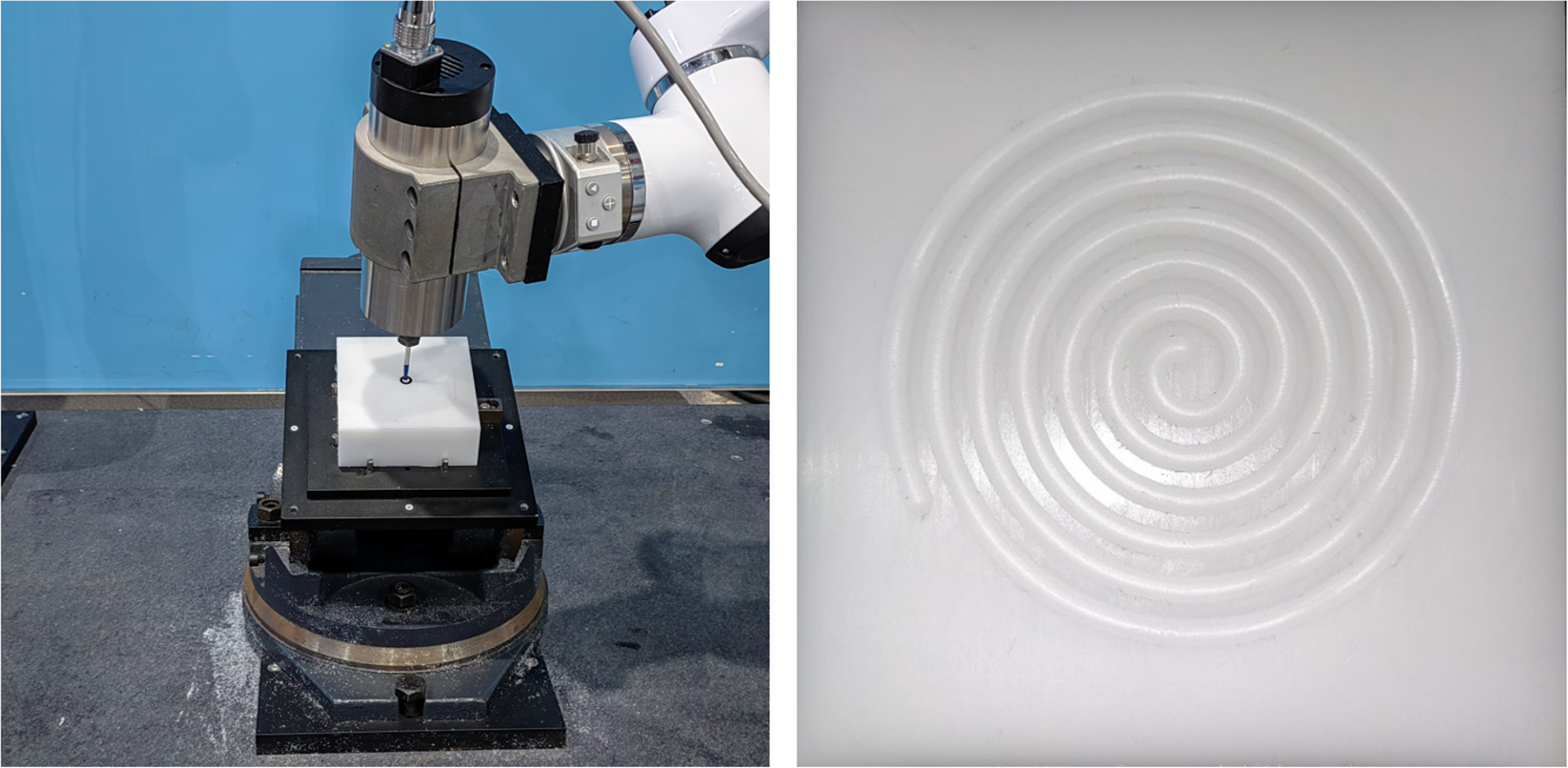
. The machining process is then carried out using the machining robot, with the results displayed in Fig. 13.
The machining process and results of the spiral line.

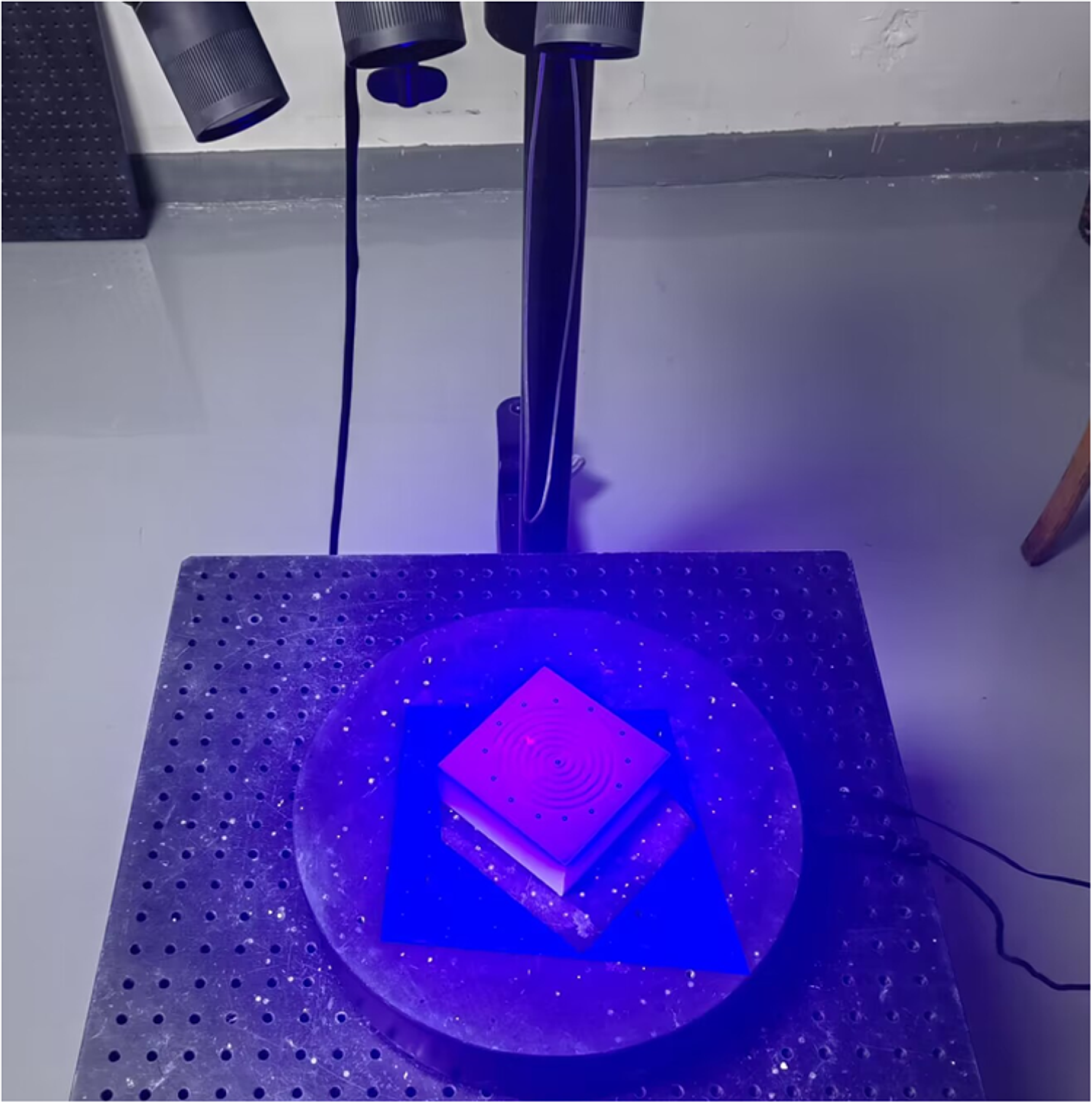
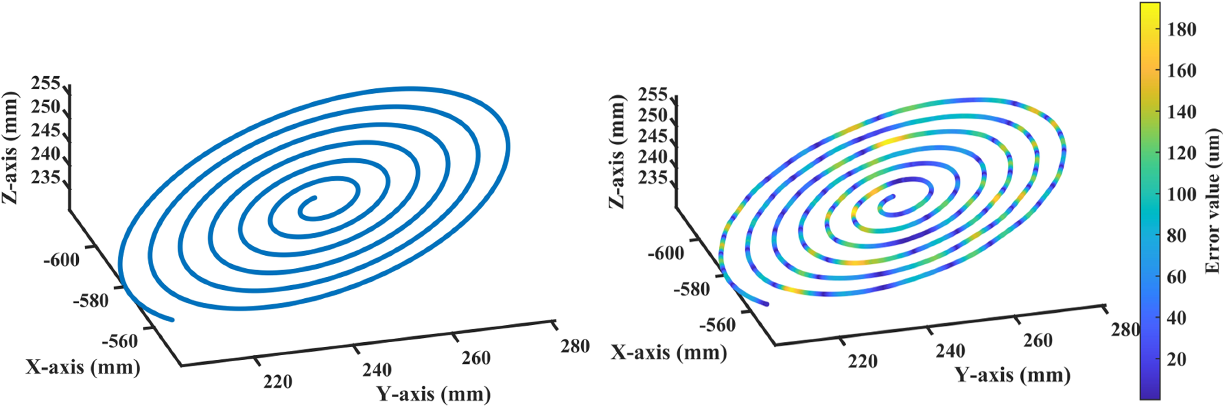
To assess the precision of the machined curve, a high-precision 3D scanner, the ATOS Q 12 M model (as shown in Fig. 14), is employed to capture point clouds and evaluate the accuracy of the curve. Measurements indicate that the average error of the spiral line is 0.073 mm. Figure 15 shows the theoretical curve of the Archimedean spiral processed in this experiment, along with the numerical values and distribution of the trajectory errors.
The process of precision measurement.

Theoretical curve diagram and error distribution diagram of the spiral line.

5.5 Verification of the sine surface machining experiment
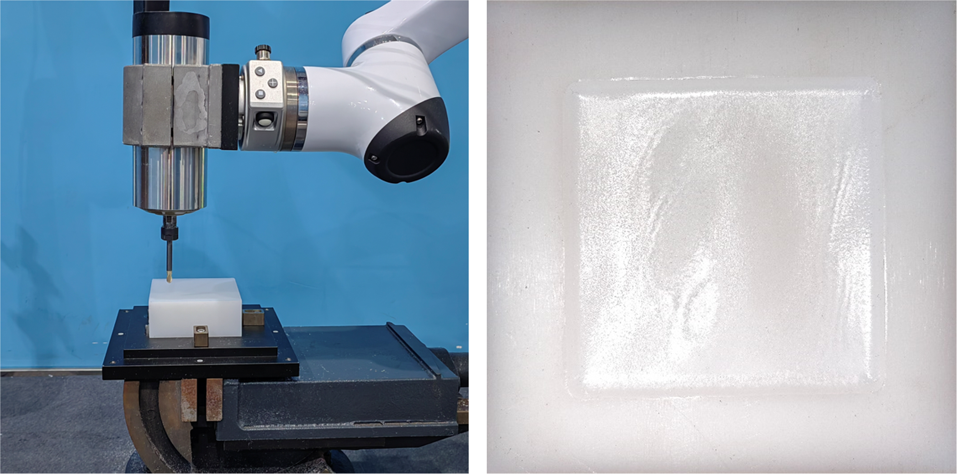
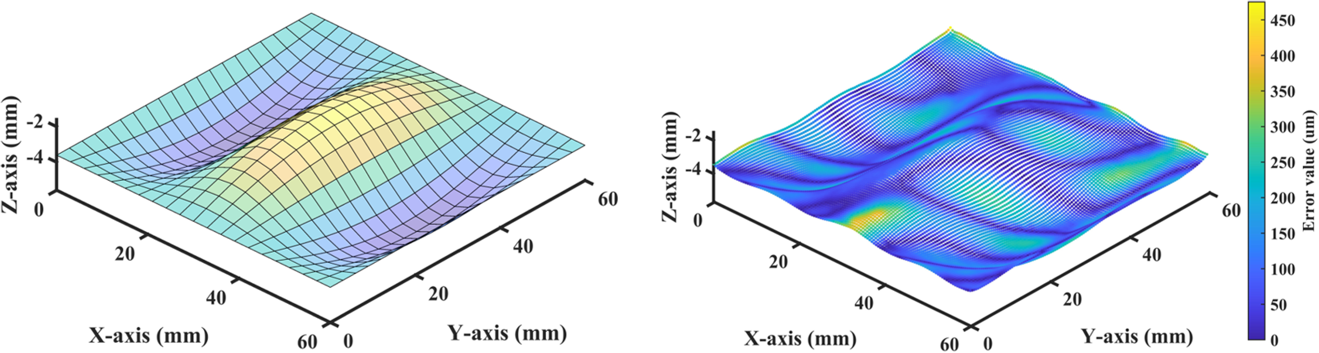
To prove the ability of the dual-robot system to accommodate small adjustments in the workspace pose, this study further adjusts the position and pose of the fixture and conducts a surface machining experiment. The fixture is rotated to the position shown in Fig. 16, and the workpiece is placed on the fixture.
The machining process and results of the sine surface.

The calibration and processing are carried out, resulting in the surface shown in Fig. 16. The accuracy of the processed surface is measured using the same equipment as shown in Section 5.3, and the results are presented in Fig. 17. The experimental results indicate that the average accuracy of the surface machining trajectory is 0.109 mm.
Theoretical surface diagram and error distribution diagram of the sine surface.

6. Conclusion
This paper presents a method for calibrating a dual-robot system within a localized space, based on the in situ measurement and a meta-heuristic algorithm (EEFO algorithm), to enhance the machining trajectory accuracy in that space. Through this calibration method, the kinematic parameters of the robot can be calibrated within the localized space, ultimately enhancing the positioning accuracy of the end-effector. Consequently, this calibration method is applicable to various operations within this area, such as machining, spraying and assembly, demonstrating its broad applicability. The final experimental results indicate that the trajectory accuracy can reach approximately 0.1 mm, thereby demonstrating the effectiveness of the proposed method. It should be noted that this paper uses milling experiments for validation; however, the proposed method is not limited to milling and can be extended to robot grinding or robot polishing.
The integrated dual-robot measurement and calibration system proposed in this study assigns the machining and measurement functions to two separate robots, overcoming the problem of increased calibration errors caused by the frequent switching of end effectors in existing single-robot machining systems during the calibration process. Compared with existing dual-robot calibration methods, the proposed method in this paper utilizes a meta-heuristic algorithm, addressing the issue of local minima often encountered in traditional gradient-based calibration techniques. The calibration method proposed in this paper still has limitations in terms of measurement data efficiency. Future work will focus on further investigating ways to improve measurement efficiency and reduce the number of measurement points.
Author contributions
Zhentao Zhang conceived and designed the study. Zhentao Zhang, Guangde Bi, and Jiajing Li conducted data gathering and analyses. Zhentao Zhang wrote the article. Lining Sun and Lei Lu provided practical feedback and guidance throughout the study.
Financial support
This research was supported by the Postdoctoral Science Foundation of China (No.2023M730348) and the Undergraduate Training Program for Innovation and Entrepreneurship, Soochow University (No. 202410285063Z). Thanks for the technical service provided by Han’s Robot.
Competing interests
The authors affirm that no conflicts of financial interest or personal relationships exist that could have inappropriately influenced the work presented in this manuscript.
Ethical approval
Not applicable.