





1. Introduction
Over the recent decades, coiling instability of a thin viscous thread falling onto a stationary or moving surface has attracted renewed attention. The phenomenon, familiar from such common culinary activities as pouring oil onto a frying pan or maple syrup onto toast (Herczyński & Lisicki Reference Herczyński and Lisicki2025), was first analysed by Barnes and co-workers (Barnes & Woodcock Reference Barnes and Woodcock1958; Barnes & Mackenzie Reference Barnes and Mackenzie1959) for the simplest case, when both the source of the stream and the planar surface on which it coils remain fixed. Even in this ‘simple’ scenario, a remarkable variety of complex coiling behaviours can ensue, depending primarily on the non-dimensional height and the flow rate, normalised using the viscosity (Ribe et al. Reference Ribe, Brun and Audoly2022). Four distinct coiling regimes can be identified, governed by different scaling regularities – viscous, gravitational, inertial-gravitational and inertial. For a compact summary of all scaling relationships and the corresponding expressions for the kinetic energy, see Herczyński & Lisicki (Reference Herczyński and Lisicki2025). In the inertial-gravitational regime, in particular, the behaviour becomes hysteretic, with multiple coiling frequencies possible under the same conditions depending on the prior evolution. In this original scenario, the phenomenon has been thoroughly elucidated experimentally (Mahadevan et al. Reference Mahadevan, Ryu and Samuel1998; Maleki et al. Reference Maleki, Habibi, Golestanian, Ribe and Bonn2004; Habibi et al. Reference Habibi, Maleki, Golestanian, Ribe and Bonn2006, Reference Habibi, Rahmani, Bonn and Ribe2010, Reference Habibi, Hosseini, Khatami and Ribe2014; Ribe et al. Reference Ribe, Huppert, Hallworth, Habibi and Bonn2006b , Reference Ribe, Habibi and Bonn2012; Sze et al. Reference Sze, Doedel, Karimfazli and Yousefzadeh2025), using theoretical models that explore its dynamics and stability (Cruickshank Reference Cruickshank1988; Tchavdarov et al. Reference Tchavdarov, Yarin and Radev1993; Maleki et al. Reference Maleki, Habibi, Golestanian, Ribe and Bonn2004; Ribe Reference Ribe2004, Reference Ribe, Habibi and Bonn2006a ,Reference Ribe, Huppert, Hallworth, Habibi and Bonn b ,Reference Ribe, Lister and Chiu-Webster c ; Habibi et al. Reference Habibi, Maleki, Golestanian, Ribe and Bonn2006, Reference Habibi, Rahmani, Bonn and Ribe2010, Reference Habibi, Najafi and Ribe2011, Reference Habibi, Hosseini, Khatami and Ribe2014; Sze et al. Reference Sze, Doedel, Karimfazli and Yousefzadeh2025), and relevant scalings (Mahadevan et al. Reference Mahadevan, Ryu and Samuel1998; Herczyński et al. Reference Herczyński, Cernuschi and Mahadevan2011; Herczyński & Lisicki Reference Herczyński and Lisicki2025). For a review, see Ribe (Reference Ribe2017). We note here a separate but related line of thought that involves the coiling of flexible ropes falling onto a solid surface (Mahadevan & Keller Reference Mahadevan and Keller1996; Habibi et al. Reference Habibi, Ribe and Bonn2007; Jawed et al. Reference Jawed, Da, Joo, Grinspun and Reis2014; Amnuanpol Reference Amnuanpol2017).
Chiu-Webster & Lister (Reference Chiu-Webster and Lister2006) opened a new chapter in the study of this phenomenon when they discovered experimentally and investigated an even larger manifold of possible behaviours in the case when the viscous thread falls onto a uniformly translating surface – a moving belt. In addition to the `stretched’ regular coiling patterns, such as loops of a variety of shapes, depending on the speed of the belt relative to flow rate and properties of the liquid, a plethora of new, unexpected patterns emerged – such as `figures of eight’, `side-kicks’, `W-patterns’ and many others (the nomenclature has not yet been standardised). This scenario, referred to as the fluid-mechanical sewing machine (FMSM), has now also been studied through experiments (Morris et al. Reference Morris, Dawes, Ribe and Lister2008; Welch et al. Reference Welch, Szeto and Morris2012), which resulted in detailed phase diagrams of the stitch patterns as a function of fall height and (linear) belt speed. Blount & Lister (Reference Blount and Lister2011) analysed the shape and stability of a very thin dragged liquid thread. In order to explore the formation of different patterns, Brun et al. (Reference Brun, Ribe and Audoly2012) performed numerical simulations using a discretised formulation of the liquid thread equations. A highly simplified, reduced `geometrical’ model has been devised by Brun et al. (Reference Brun, Audoly, Ribe, Eaves and Lister2015), and proved surprisingly adept in capturing some of these complex patterns – but only in the non-hysteretic regime that is for the limited range of falling heights. A detailed review was provided by Ribe et al. (Reference Ribe, Brun and Audoly2022).
It should be noted that the reverse scenario, wherein the origin of the viscous filament translates uniformly while the surface onto which the thread falls is stationary, has not yet been taken up in the literature. The two scenarios are not physically equivalent, since in the first case the thread is dragged by the moving belt from below, whereas in the second it is pulled along the fixed surface from above. Furthermore, it is clear that when the thread is dragged by a moving surface, it will deform from the bottom up rather than from the top down, which is the case when its origin is displaced. The second of these scenarios is harder to implement experimentally (the belt can run continuously, but the thread cannot be moved at constant velocity indefinitely), and the geometrical model cannot be easily adopted either. Consequently, this paper only takes up the first arrangement, the situation when the source (nozzle) of the viscous jet is stationary and the surface below moves.
While the numerical approaches and the geometrical model of Brun et al. (Reference Brun, Audoly, Ribe, Eaves and Lister2015) could in principle be extended to include accelerating the surface below the falling jet, experiments whereby the speed of the belt would vary, whether uniformly or not, have not yet been reported and would be quite challenging to perform owing to the high sensitivity of the viscous stream to any perturbations. Thus the role of acceleration in the FMSM in deforming and perhaps augmenting the `repertoire’ of possible patterns, or modifying the transition speeds between them, remains to be explored.
In the present contribution, a rotational version of the FMSM (or R-FMSM) is studied both experimentally and theoretically. In this scenario, the surface onto which the viscous thread falls is rotating about a fixed axis at a constant angular velocity. Experimentally, this is the simplest case in which the surface under the stream is locally accelerating, rather than moving at a constant velocity. It is also perhaps the most natural extension of the previous work on coiling phenomena, wherein rotational effects are present, and with applications to variety of culinary (Herczyński & Lisicki Reference Herczyński and Lisicki2025) and artistic explorations, with edible viscous liquids or with paints. The problem of elastic coiling of a rope falling on a rotating surface was previously explored theoretically and numerically by Amnuanpol (Reference Amnuanpol2019, Reference Amnuanpol2021, Reference Amnuanpol2022), who classified the resulting shapes as epitrochoids or hypotrochoids, which we will later simply refer to as inward and outward coiling patterns, respectively.
This investigation follows on from and extends our earlier, preliminary exploration of R-FMSM (Lisicki et al. Reference Lisicki, Adamowicz, Herczyński and Moffatt2022), with a completely new and improved experimental set-up, enabling a much finer control of the angular speed and other experimental parameters. We also include comparisons of the observed thread patterns with simple heuristic arguments and with the results of an appropriately modified geometrical model of Brun et al. (Reference Brun, Audoly, Ribe, Eaves and Lister2015). An attempt is also made to standardise the nomenclature, and to identify a series of patterns, which almost always follow one another as the speed, whether translational or rotational, is gradually increased. We refer to this series as the main sequence. The main sequence may be augmented by additional stable patterns, and does not encompass ephemeral, unstable traces, which often accompany transitions from one pattern to another, but is invariably manifest, in experiments and theoretical models as well.
The paper is organised as follows. In § 2, the experimental apparatus is described in detail. Section 3 contains a summary of the experimental results and a discussion of the differences between translational (FMSM) and rotational (R-FMSM) cases. Section 4 takes up comparisons of the observed traces with a simple heuristic argument and the theoretical predictions of the geometrical model. The discussion of all results and concluding remarks are presented in § 5.
Experimental set-up. The rotating table supports an acrylic plate onto which the viscous thread falls, and its angular speed (anticlockwise) is controlled by a stepper motor connected to a laptop. Fluid is supplied at a constant flow rate using a (red) syringe pump visible on the left. Deposited oil is removed ahead of the point of contact of the stream with the plate by a (green) scraper, and removed from the centre between runs.

Figure 1. Long description
A laboratory setup for studying the coiling instability of a viscous thread falling onto a rotating plate. The setup includes a rotating table supporting an acrylic plate, a stepper motor controlled by a laptop, a syringe pump for fluid supply, and a scraper for removing deposited oil.
2. Experimental procedure
The experiment used a custom-made rotating table, designed and manufactured at the Faculty of Physics, University of Warsaw. The rotating surface was supported by rubber roller-blade wheels that rolled on a stationary disc and were set in motion by a stepper motor. The radius of the rotating disc was
 $R_0=75$
cm, with a smaller circular acrylic plate (polymethyl methacrylate) of radius
 $R_1=55$
cm and thickness 0.5 cm attached to it. The acrylic surface served three purposes: it provided a convenient, smooth substrate onto which the thread of viscous oil could fall; it allowed the use of a scraper to remove oil accumulating on the rotating table; and it protected the ruled paper underneath, which was used to measure distances from the centre of the spinning disc, as well as angular displacements. A general view of the experimental set-up is shown in figure 1. We describe each of its elements in detail below.
The rotating table together with the stepper-motor was supported by a metal cart. The motor was positioned below, with the rubber wheels attached to its axis and making direct contact with the lower surface of the rotating table. The cart also supported horizontal aluminium rails above the table, to which a vertical ruler was fastened. The ruler served to hold in place a flexible polyethylene see-through tube, of inner diameter
 $4$
mm, attached at the other end to a syringe pump (New Era Instruments NE-1000). This mechanism provided control of the flow rate. The orifice was a brass nozzle of inner diameter
 $d_n=3$
mm attached to the end of the tube and fastened to the ruler. The rails allowed regulation of the distance of the nozzle from the centre of the rotating table. The horizontal position of the end of the nozzle and its height above the rotating table were adjusted manually. The five selected radii
 $R\in \{3, 6, 9, 12, 15\}$
cm, and four selected heights
 $H\in \{3, 5, 7, 9\}$
cm above the turntable, were easily accessible in this set-up. To provide comparison with earlier experiments of Lisicki et al. (Reference Lisicki, Adamowicz, Herczyński and Moffatt2022), the flow rates were restricted to two,
 $Q=2$
and
 $3$
ml min−1.
Attached to the rails above the turntable was also a scraper, made from a simple windshield wiper, which was positioned on the opposite side of the turntable from the nozzle, and fixed so that its rubber blade pressed tightly against the acrylic disc. This system worked well to clear the oil deposited on the surface ahead of the continuous stream (the table was rotating anticlockwise), although a thin film of oil would remain on the surface. Excess oil was collected near the centre of the table, and removed between experimental runs (and occasionally during a run).
The working liquid was a Tornado silicone oil of density
 $\rho = 996\ \rm{kg}\ \rm{m}^{-3}$
, kinematic viscosity
 $\nu = 0.03\ \rm{m}^2\ {s}^{-1}$
, and surface tension
 $\sigma =21.5\times 10^{-3}\ \rm{N}\ {m}^{-1}$
, as reported by the manufacturer. To maintain constant viscosity of the oil, the laboratory room temperature was controlled and kept at
 $21\, ^\circ \text{C}$
, with maximum variations of approximately
 $1\, ^\circ \text{C}$
.
The stepper motor was controlled via a home-made interface based on an RS232 terminal Termite, with rotation rates indicated in arbitrary units, later converted to Hz. During experimental runs, the rotation rate
 $\omega$
of the turntable was gradually adjusted, in steps of
 $(1.3{-}7)\times 10^{-3}$
Hz. A typical response time of the system, from the moment the new speed was entered in Termite to the new steady-state rotation, was approximately 1 s, and always less than 2 s. The range of accessible rotation rates was
 $0.001{-}0.5$
Hz, with an accuracy of approximately
 $10^{-3}$
Hz, so that the associated angular speeds of the table,
 $\varOmega =2\pi \omega$
, were in the range
 $0.006{-}3.1$
Hz.
All experimental runs were filmed using a built-in camera of an iPhone 15 Pro. The table was illuminated with a large (
 $40\times 40\ \text{cm}^2$
) array of diode lights, and the camera was held fixed above the surface by a separate supporting arm attached to a stand. It was positioned so that the nozzle’s end and a sliver of the rotational surface were visible, large enough to capture the deposited oil trace starting from the point of contact and extending along the arc where the pattern retained its distinct shape. The trace gradually lost its contours as the oil spread on the surface, a process that took approximately 1 s to complete.
During each run, the changes in the angular speed were read and recorded, and the performance of the entire system was carefully monitored in order to help correlate angular velocities with the observed traces and transitions between different patterns. Because the coiling patterns were susceptible to perturbations, and to ensure reliable results, experiments were frequently run `in reverse’, i.e. with gradually decreasing rather than increasing angular speeds. This was especially necessary when the nozzle was at
 $H=7$
cm above the rotating surface, where intermittent and unstable behaviour was expected, as discussed later. Repeating measurements at a given angular speed, with approach from below and from above, served to uncover any hysteretic behaviour and to check the reliability of the measurements.
The experiments were carried out over a period of three weeks, and some of the oil was collected after each run, then recycled and reused. The rotating surface was carefully scraped of oil and dried before each run, and thoroughly cleaned using oil solvents at the end of each experimental session, usually after three or four runs, during which the principal experimental parameters
 $H$
,
 $R$
and
 $Q$
were held fixed.
3. Summary of results
We present the results of the experiments using dimensionless parameters of the system. To compare our set-up with those used earlier for the translational version of the experiment (Morris et al. Reference Morris, Dawes, Ribe and Lister2008), the FMSM, it is helpful to consider the governing dimensionless parameters of the system. The experimental conditions are specified by six constant physical parameters
 $({d_n}, {Q}, \rho , \nu , \sigma , {g})$
, which depend on three base SI units (kg, m, s), so that based on the Buckingham pi theorem, the system can be characterised by three dimensionless parameters, which we take to be
 \begin{equation} \varPi _{1} = \left ( \frac {\nu ^{5}}{gQ^{3}} \right )^{1/5} \!, \quad \varPi _{2} = \left ( \frac {\nu Q}{g d_n^{4}} \right )^{1/4} \!, \quad \varPi _{3} = \frac {\sigma d_n^{2}}{{\rho \nu }Q} . \end{equation}
The values of these parameters were the same as in Lisicki et al. (Reference Lisicki, Adamowicz, Herczyński and Moffatt2022). For
 $Q=2$
ml min−1, they were
 \begin{equation} \varPi _{1} = {582} , \quad \varPi _{2} = {1.06} , \quad \varPi _{3} = {0.19}, \end{equation}
while for
 $Q=3$
ml min−1,
 \begin{equation} \varPi _{1} = {456} , \quad \varPi _{2} = {1.17} , \quad \varPi _{3} = {0.13} . \end{equation}
The first parameter,
 $\varPi _{1}$
, is smaller but within 9 % of the value reported in Morris et al. (Reference Morris, Dawes, Ribe and Lister2008). The other two dimensionless parameters differ by factors 2.4 and 0.13, respectively, primarily due to the different nozzle diameter
 $d_n$
, which was twice as large in Morris et al. (Reference Morris, Dawes, Ribe and Lister2008) as here.
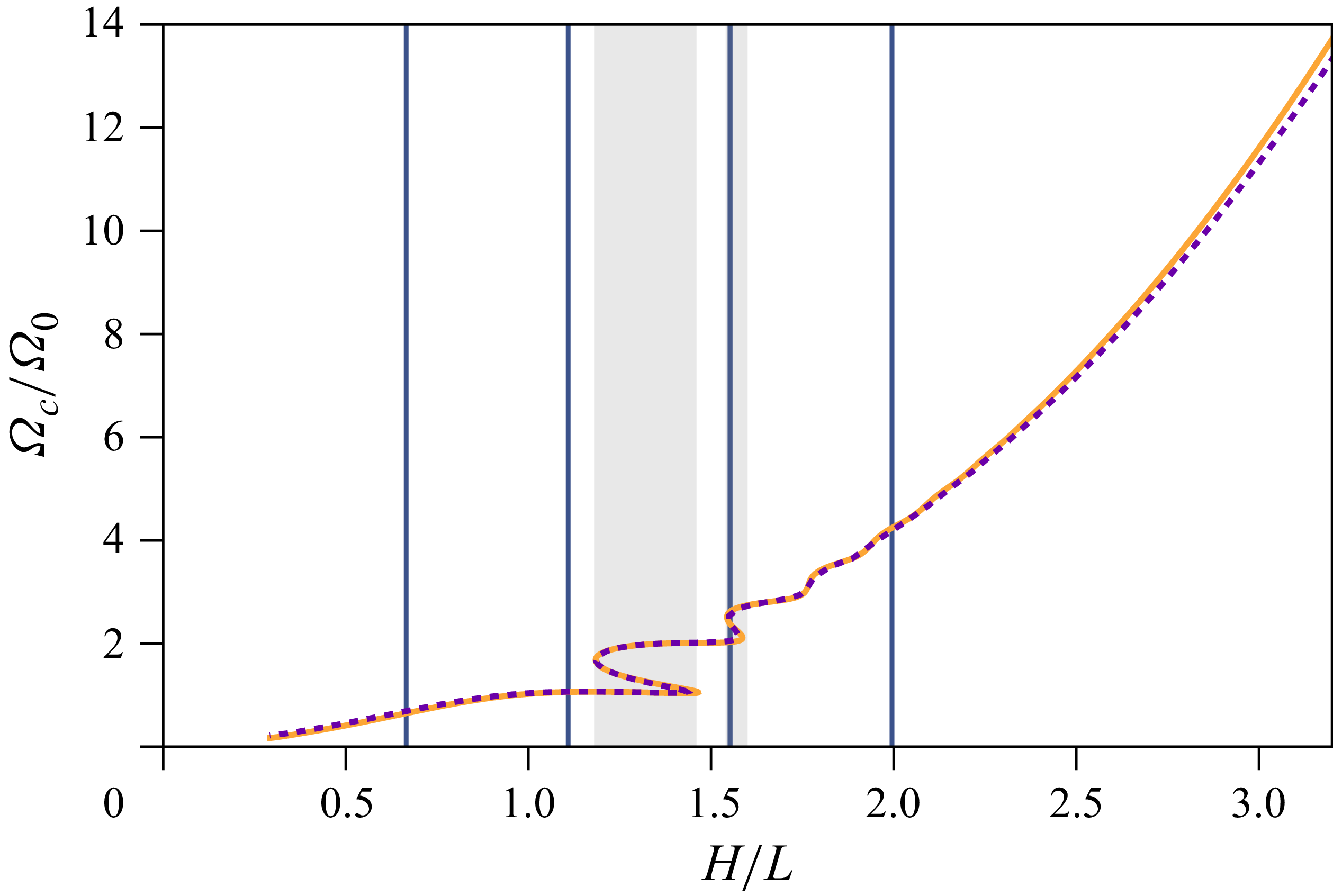
The physics of coiling of a liquid thread on a stationary surface depends on its fall height. The steady angular frequency of coiling
 $\varOmega _c$
can be found using the method of Ribe (Reference Ribe2004). Figure 2 displays the normalised coiling frequency as a function of normalised height for the parameters of the working fluid and the flow rates in the present experiment. In this case, the coiling angular frequency was rescaled by
 $\varOmega _0=(g^2/\nu )^{1/3}=14.75$
Hz. For general unsteady dynamics, the frequency of coiling can be determined in numerical simulations using a discrete viscous rods (DVR) reduced model (Audoly et al. Reference Audoly, Clauvelin, Brun, Bergou, Grinspun and Wardetzky2013). The characteristic experimental length scale for the fluid can be constructed as
 $L=({\nu ^2}/{g})^{1/3}=4.51$
cm. The experimental fall heights are marked in figure 2 with blue vertical lines. The lowest two heights correspond to the gravitational regime (G), the third lies in the multi-valued inertial-gravitational regime (IG), and the fourth and largest height is in the inertial regime (I).
Dimensionless angular coiling frequency versus dimensionless drop height for a liquid jet impinging on a stationary substrate, calculated using the method of Ribe (Reference Ribe2004). The shaded area indicates the multi-valued region. There is only a slight dependence on the flow rate: orange solid line indicates
 $Q=2\ \rm{ml\ min^{-1}}$
; purple dashed line indicates
 $Q=3\ \rm{ml\ min^{-1}}$
. Vertical grid lines indicate the experimental heights used in this work.

Selected experimental frames showing the patterns that recur in all cases dubbed the `main sequence’, for
 $H=5\ \text{cm}$
,
 $R=3\ \text{cm}$
and
 $Q=2\ \rm{ml\ min^{-1}}$
: (a) outward and (b) inward loops occurring at the same, low rotation rate
 $\omega =0.079\,\text{Hz}$
. Upon increasing
 $\omega$
, the patterns transition to one-by-one (c) at
 $\omega =0.093\,\text{Hz}$
, and then to meanders (d) at
 $\omega =0.13\,\text{Hz}$
, which gradually flatten (e, f) to a circle (‘catenary state’, not shown) at
 $\omega =0.23\ \text{Hz}$
.

Selected experimental frames showing the patterns that recur in all cases dubbed the `main sequence’, for
 $H=5\ \text{cm}$
,
 $R=15\ \text{cm}$
and
 $Q=2\ \rm{ml\ min^{-1}}$
: (a) outward and (b) inward loops occurring at low rotation rates
 $\omega =0.013\,\text{Hz}$
and
 $\omega =0.019\,\text{Hz}$
, respectively. Upon increasing
 $\omega$
, the patterns transition to one-by-one (c) at
 $\omega =0.020\,\text{Hz}$
, and then to meanders (d) at
 $\omega =0.025\,\text{Hz}$
, which gradually flatten (e, f) to a catenary (not shown) at
 $\omega =0.060\,\text{Hz}$
. In this case, the sharp shadows are caused by lighting from the side.

For the gravitational regime of coiling, and the lowest fall height, a representative catalogue of stitching patterns is presented in figure 3 (for
 $H=5$
cm,
 $R=3$
cm), where the stream falls relatively close to the rotation axis, and figure 4 (for
 $H=5$
cm,
 $R=15$
cm), further away from the axis, for the same flow rate
 $Q=2$
ml min−1. In this regime, five common patterns occur sequentially in all cases when the table rotates. The first four, in order of increasing angular velocity, are: translating coiling (inward or outward), one-by-one (when the coils alternatively point inwards or outwards), and meanders. In the fifth, for high speeds of rotation, the falling thread follows an approximate catenary, and the corresponding pattern asymptotes to a circle; consistent with the terminology introduced in Chiu-Webster & Lister (Reference Chiu-Webster and Lister2006), we refer to it as a `catenary regime’. The same forms appear also in the case of a translating surface of the FMSM, in the same order (with the catenary pattern a straight line), and they are therefore referred to as the `main sequence’.
Selected experimental frames showing the patterns observed for larger fall heights
 $H=7$
cm, and in (g)
 $H=9$
cm, all at
 $Q=2$
ml min−1: (a,b) slanted loops, (c) braiding, (d,e) one-by-zero, or W-pattern, both inwards and outwards, (f) double coils, (g) two-by-two, with pairs of loops alternately coiling inwards and outwards, (h) slanted meanders, (i) disorder.

For higher thread fall heights,
 $H= 7$
or
 $9$
cm, additional patterns appear, a selection of which is presented in figure 5. New coiling patterns were observed in between the forms of the main sequence. These patterns include slanted loops in figures 5(a,b), braiding in figure 5(c), double coils in figure 5(f), two-by-one (not pictured), and two-by-two in figure 5(g). A form present in many experiments, predicted theoretically to follow translating coils and precede meanders, is the one-by-zero (figure 5
d,e), also called the W-pattern (Brun et al. Reference Brun, Audoly, Ribe, Eaves and Lister2015; Sze et al. Reference Sze, Doedel, Karimfazli and Yousefzadeh2025). In this pattern, the loops are all pointing in the same direction, as in translating coils, but are clearly separated by connecting cords of varying curvature. In the experiments, one-by-zero appeared for
 $H=7$
and
 $9$
cm (figure 7) and at
 $H=3$
cm only for
 $R=3$
cm and
 $Q=3$
ml min−1, and for
 $R=6$
cm and
 $Q=2, 3$
ml min−1. The other patterns are relatively rare and appear over a limited range of linear speeds. Moreover, they may vary in details, e.g. in the spacings between the loops or coils, and in their inclination. The patterns of the main sequence can occur in a variety of sub-forms, e.g. meanders can be slanted (figure 5
h), radially asymmetric, or tangentially asymmetric. Disordered patterns (such as in figure 5
i) are intermittently seen between stable ones, when the stream is in transition between steady coiling behaviours or when the angular speed of the table is changing.
Phase space of patterns within the `main sequence’, for different distances
 $R$
from the rotation axis for (a)
 $H=3\ \text{cm}$
and
 $Q=2\ \rm{ml\ min^{-1}}$
, (b)
 $H=3\ \text{cm}$
and
 $Q=3\ \rm{ml\ min^{-1}}$
, (c)
 $H=5\ \text{cm}$
and
 $Q=2\ \rm{ml\ min^{-1}}$
, (d)
 $H=5\ \text{cm}$
and
 $Q=3\ \rm{ml\ min^{-1}}$
.

Figure 6. Long description
Four scatter plots depict the phase space of patterns within the main sequence for different distances from the rotation axis and flow rates. Panel A: The scatter plot shows the relationship between the normalized velocity (V/V0) and the normalized distance from the rotation axis (R/L) for a height of 3 centimeters and a flow rate of 2 milliliters per minute. Different symbols represent various coiling patterns: unstable, outward coiling, inward coiling, 1-by-1, 2-by-1, meander, and catenary. Panel B: The scatter plot shows the relationship between the normalized velocity (V/V0) and the normalized distance from the rotation axis (R/L) for a height of 3 centimeters and a flow rate of 3 milliliters per minute. Different symbols represent various coiling patterns: unstable, outward coiling, inward coiling, 1-by-1, 2-by-1, meander, and catenary. Panel C: The scatter plot shows the relationship between the normalized velocity (V/V0) and the normalized distance from the rotation axis (R/L) for a height of 5 centimeters and a flow rate of 2 milliliters per minute. Different symbols represent various coiling patterns: unstable, outward coiling, inward coiling, 1-by-1, 2-by-1, meander, and catenary. Panel D: The scatter plot shows the relationship between the normalized velocity (V/V0) and the normalized distance from the rotation axis (R/L) for a height of 5 centimeters and a flow rate of 3 milliliters per minute. Different symbols represent various coiling patterns: unstable, outward coiling, inward coiling, 1-by-1, 2-by-1, meander, and catenary.
Phase space of patterns at larger drop heights, for different distances
 $R$
from the rotation axis for (a)
 $H=7\ \text{cm}$
and
 $Q=2\ \rm{ml\ min^{-1}}$
, (b)
 $H=7\ \text{cm}$
and
 $Q=3\ \rm{ml\ min^{-1}}$
, (c)
 $H=9\ \text{cm}$
and
 $Q=2\ \rm{ml\ min^{-1}}$
, (d)
 $H=9\ \text{cm}$
and
 $Q=3\ \rm{ml\ min^{-1}}$
.

The exact shape of most patterns depends on whether the thread itself is spinning clockwise or anticlockwise, and it may spontaneously change direction from one to the other. The outward pointing loops, as in figure 3(a), correspond to the stream coiling anticlockwise, whereas the inward pointing loops, as in figure 3(b), are due to clockwise spin. The one-by-one pattern, shown in figure 3(c), with alternating inward and outward loops, depends on the thread switching the direction of the coiling with each cycle. The same is true for the linear case, the FMSM, wherein the one-by-one loops switch between left and right.
While the order in which new patterns appear in the rotational case generally follows the sequence in the linear set-up, coiling on a rotating circular table introduces two separate mechanisms of deforming the stitching patterns relative to the classical FMSM. The first is a purely geometrical effect, which consists of bending of the falling filament to accommodate the curvature imposed by the rotating surface. In this case, since the local linear speed
 $V=2\pi \omega R$
is larger for larger radii, the arcs pointing inwards would be stretched relative to those pointing outwards, and therefore less sharp.
The second mechanism is dynamical, due to the superposition of the velocity of the coiling thread and the local velocity of the table at the point of contact, and depends on the direction of coiling. The table always rotates anticlockwise, so for the anticlockwise coiling, the segments of the thread further away from the axis will be stretched less than those closer to the axis. In this case, the arcs pointing outwards will be sharper than those pointing inwards. But when the coiling is clockwise, the effect will be reversed, with the arcs pointing inwards becoming sharper than those pointing outwards. In the first case, the two mechanisms reinforce each other; in the second, they are in competition. Both decrease with increasing
 $R$
, as the local curvature decreases.
These subtle effects can be appreciated by looking closely at figures 3 and 4. At
 $R=3$
cm, meanders in figures 3(d,e) are deformed in such a way that the sharper arcs are pointing outwards and broader ones inwards. As can be verified in the videos, from which these pictures were extracted, in both cases the thread is coiling anticlockwise.
By contrast, at
 $R=15$
cm, figures 4(d,e), the more pointy arcs are directed inwards. Indeed, in these two cases, the thread was coiling clockwise. The overall effect is smaller for
 $R=15$
cm than for
 $R=3$
cm, since the geometrical and dynamical mechanisms cancel each other to some degree.
Furthermore, a careful comparison of figures 3(a) and 3(b) brings up a very fine but nevertheless discernable difference in the shape of the loops pointing outwards and inwards. The loops in the latter case are clearly broader than those in the former. This should be expected since the thread was coiling anticlockwise and clockwise, respectively, in these two cases. A similar effect can be seen in the one-by-one pattern, figure 3(c). The reverse effect, with outward pointing loops being broader than those pointing inwards, can perhaps be seen in figures 4(a,b), but here the difference is less clear.
The rotation rate corresponding to the deformed meanders in figure 3(d), where
 $\omega =0.13$
Hz, is much higher than for the meanders in figure 4(d) at
 $\omega = 0.025$
Hz, but the linear speeds
 $V$
in the two cases are nearly the same, namely 2.45 and 2.39 cm s−1, respectively. This allows for a comparison of the rotational (geometrical and dynamical) effects alone, which differ in the two cases considered above.
Consideration of the rotational effects brings up the question of whether rotational inertia plays any role in the form of the deposited threads. For the case illustrated in figure 3(d), the centrifugal effect per unit length can be estimated as
 $\rho \pi a^2(2\pi \omega )^2{}R\sim 10^{-5}$
N m−1, where
 $a$
is the radius of the thread when it comes to rest on the table,
 $a\sim 0.5$
mm. The viscous force per unit length resisting stretching of the thread during coiling can be estimated to be of order
 $10^{-3}$
N m−1, two orders of magnitude larger than the inertial effects, so clearly the latter can be neglected. Indeed, to observe centrifugal effects would require the rotating table to spin at least one order of magnitude faster, at which point the trace pattern would have long since become a circle.
Figures 6 and 7 provide a summary of all the stitching patterns observed, for the four heights, five radial distances and two flow rates
 $Q=2$
and
 $Q=3$
ml min−1, and cover the full range of linear velocities explored in the experiments. For the sake of comparison, the data are presented in dimensionless terms. Apart from the characteristic length
 $L=4.51$
cm defined before,
 $\omega _0=0.1$
Hz is taken as the typical frequency suitable for the normalisation of the experimental results, and
 $V_0= 2\pi \omega _0 L=2.83$
cm s−1 is taken as the normalising linear speed. The four non-dimensional heights selected were thus
 $H/L \in \{0.67, 1.11, 1.55, 2.00\}$
. The five radial distances examined in the experiments were
 $R/L \in \{0.67, 1.33, 2.00, 2.66, 3.33\}$
.
While unstable patterns have been observed in all cases, particularly in transitions between distinct coiling patterns, true hysteretic behaviour was observed only for the two larger radii, and most readily for
 $H=7$
cm, the only height explored within the IG regime (the multi-valued regime, seen for a stationary surface in figure 2). The only exceptions were coils, which could point inwards or outwards. As figures 6 and 7 indicate, the inward and outward pointing coils are very nearly equally probable, suggesting that the particular direction emerges as the result of initial conditions. Once the direction was established, in most cases it tended to persist as the angular speed was increased, as seen especially clearly in figures 6(b) and 7(b). Nevertheless, in our experiments, outward pointing coils appear more likely at low heights
 $H=3$
and
 $5$
cm at
 $Q=2$
ml min−1, and less likely at larger heights and larger flow rates.
It is useful to compare the measurements described here with those that we conducted in our first rotating system. Figure 8 combines data obtained in our preliminary experiment (Lisicki et al. Reference Lisicki, Adamowicz, Herczyński and Moffatt2022) with the new measurements, and indicates the patterns observed as a function of normalised angular and linear speeds. Since in the current experiment the angular speed was varied for five selected radii
 $R$
, the data align along straight lines, whose slopes correspond to those radii. In our earlier experiment (Lisicki et al. Reference Lisicki, Adamowicz, Herczyński and Moffatt2022), setting a desired angular speed was cumbersome, so it was chosen at the start of each run and then kept constant while the radius was varied. The resulting data points are therefore aligned along vertical lines corresponding to the three angular speeds selected. The two sets of straight lines intersect (or very nearly intersect) at five points corresponding to those parameters
 $\omega$
and
 $R$
, which were accessible in both experiments. In all five cases, the patterns observed in two different set-ups were the same. For the large radii, above
 $R = 9$
cm, the lines corresponding to the new and earlier measurements do not intersect; however, interpolating the new data suggests the same pattern as in the earlier experiment, a circle. It is thus seen that two experiments that differed significantly and used different procedures are in a very good agreement.
Comparison of new experimental patterns with those from Lisicki et al. (Reference Lisicki, Adamowicz, Herczyński and Moffatt2022) (plotted in grey). New experimental data are plotted for
 $R=3\ \text{cm}$
(purple),
 $R=5\ \text{cm}$
(magenta),
 $R=9\ \text{cm}$
(ochre),
 $R=12\ \text{cm}$
(orange),
 $R=15\ \text{cm}$
(yellow). Measurements were made by varying
 $\omega$
at constant
 $R$
, and thus follow straight lines in the
 $(\omega , V)$
plane. Approximate regions of subsequent patterns are marked by blue horizontal lines. Inward and outward coiling are not distinguished.

4. Theoretical analysis
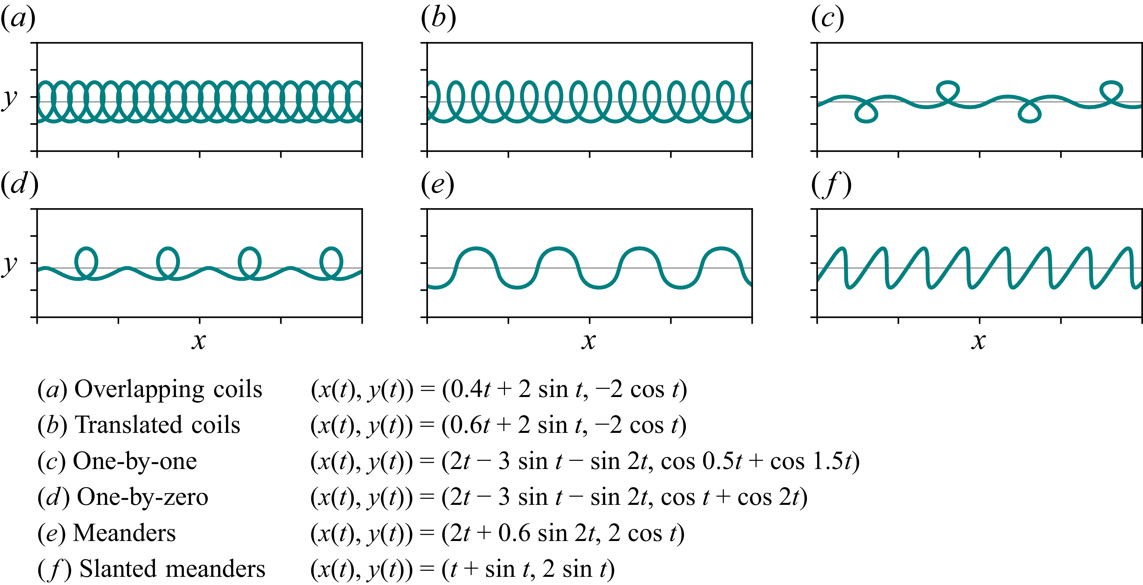
Parametric representation of the patterns appearing in the main sequence, together with the intermittent one-by-zero (W-pattern) and slanted meanders. Translation is imposed by the linear component in the
 $x$
-direction.

Before a more detailed theoretical analysis, it is helpful to consider a simple, heuristic argument. The ‘regular’ coiling instability, wherein both the source of the viscous stream and the substrate onto which it falls remain at rest, may take a number of forms: usually circular loops, but also folds along a particular direction (stationary or itself rotating). Since all such patterns can be regarded as superpositions of two independent oscillations in perpendicular directions, it is reasonable to expect that shapes obtainable in the FMSM and R-FMSM may be similarly decomposed, along the belt and transverse to it in the first case, and along the azimuthal and radial directions in the second. For the case of fluid-dynamical stitching on a moving belt, a number of authors analysed Fourier spectra of the patterns and observed distinct, harmonic components, and the resulting closed trajectories in the
 $(x,y)$
plane (Brun et al. Reference Brun, Ribe and Audoly2012; Welch et al. Reference Welch, Szeto and Morris2012; Ribe et al. Reference Ribe, Brun and Audoly2022). To show that the observable patterns may be `constructed’ with such superpositions, at least approximately, figure 9 displays representations of the six common patterns, including those of the main sequence (omitting the circle), as parametric plots of simple linear and sinusoidal functions. The linear components appear only in the
 $x(t)$
coordinate corresponding to the local direction of velocity (along the belt or azimuthal), while the amplitudes and frequencies were chosen with the help of the Fourier spectra corresponding to a given pattern (Sze et al. Reference Sze, Doedel, Karimfazli and Yousefzadeh2025). Alternatively, as pointed out in Brun et al. (Reference Brun, Ribe and Audoly2012), the patterns can be explained by phase differences and frequency ratios.
Qualitatively similar patterns may result from the bending of elastica, ideal infinitesimally thin and inextensible elastic rods on a plane, first analysed by Jacob Bernoulli in 1691. There are nine classes of such patterns, including a circle, translated coils, figure eight and bunched-up meanders (Matsutani Reference Matsutani2010), clearly reminiscent of fluid-dynamical stitching patterns.
(a) Scheme of the set-up of the geometrical model of coiling in the rotating system. The thick green curve denotes the trace, parametrised by the arc length
 $s$
. The dashed red curve is the orbit of the contact point around the point
 $O$
, being the projection of the nozzle onto the rotating table. Polar coordinates
 $(r,\psi )$
describe the position of the point of contact
 $\boldsymbol{r}$
. Its distance from the axis of rotation of the table is denoted by
 $\boldsymbol d$
. (b) Integration of model B, where
 $\varOmega =0.05 \,\varOmega _c$
is kept fixed while
 $R$
continuously increases,
 $R=R_c+s/50$
and
 $0\leqslant s/R_c\leqslant 1050$
. The portion of the solution in the top right quadrant of the substrate is shown. (c) Corresponding snapshots of the contact point trajectory for
 $p\leqslant s/R_c\leqslant p+50$
, with
 $p$
varying from 0 to 1000 in increments of 100.

Figure 10. Long description
Panel A: This diagram illustrates the setup of a geometric model for coiling in a rotating system. A thick green curve represents the trace, parameterized by the arc length. A dashed red curve shows the orbit of the contact point around a central point, which is the projection of the nozzle onto the rotating table. Polar coordinates describe the position of the contact point, with its distance from the axis of rotation denoted. Panel B: This plot shows the integration of model B, where rotation frequency is kept fixed while the radius R increases. The portion of the solution in the top right quadrant of the substrate is displayed. Panel C: This series of plots shows snapshots of the contact point trajectory corresponding to the traces shown in panel B.
The patterns seen in the main sequence in the stable, gravitational regime of coiling, can be rationalised using a modified version of the simple geometrical model, introduced by Brun et al. (Reference Brun, Audoly, Ribe, Eaves and Lister2015). In the present model, a thread is falling on a table, which moves horizontally with speed
 $\boldsymbol{V}$
that varies in space. When the table is stationary, and thus
 $V=0$
, the thread coils with radius
 $R_c$
and angular speed
 $\varOmega _c$
, which for a given fall height
 $H$
is calculated in figure 2. The thread, treated as a filament of uniform thickness, falls onto the table at velocity
 $U_c=\varOmega _c R_c$
. Then it quasi-statically bends and is laid down on the surface, as sketched in figure 10(a). We introduce a local frame of reference, with
 $\boldsymbol{r}$
denoting the position of the point of contact of the thread with the table. The origin
 $O$
(
 $\boldsymbol{r}=0$
) is the position of the projection of the dispensing nozzle on the rotating table. The distance from
 $O$
to the axis of rotation of the table is the experimentally controlled parameter
 $R$
. The angular speed of rotation of the table is
 $\varOmega = 2\pi \omega .$
Using the notation from the figure, the no-slip boundary condition at the contact point between the thread and the substrate reads
 \begin{equation} U_c\boldsymbol{t} + \boldsymbol{V}= \dot {\boldsymbol{r}}, \end{equation}
where
 $\boldsymbol{t}$
is the unit tangent vector of the thread at the (non-material) point of contact
 $\boldsymbol{r}$
of the thread with the substrate,
 $\dot {\boldsymbol{r}}$
is the velocity of this point in the laboratory frame, and
 $\boldsymbol{V}$
is the local translational velocity of the rotating table. For
 $\boldsymbol{V}=0$
, stationary coiling with constant speed
 $U_c$
is recovered. In general, when the speed of the table is lower than the speed at which the thread is deposited,
 $\dot {\boldsymbol{r}}\neq 0$
and the excess length of the thread is deposited on the table in the form of coiling patterns.
The position of the point of contact
 $\boldsymbol{r}$
is parametrised in the cylindrical polar basis
 $(\boldsymbol{e}_r, \boldsymbol{e}_\psi )$
as
 $(r(s),\psi (s))$
, where
 $s$
is the arc length such that the point at
 $s=0$
corresponds to the fluid that touched the surface at
 $t=0$
. Thus
 $s=U_c t$
corresponds to the point of contact at time
 $t$
, and
 $s$
is a time-like variable (here,
 $U_c$
is kept constant).
As can be deduced from figure 10(a), the distance of the point of contact from the rotation axis,
 $\boldsymbol{d}$
, can be written as
 $\boldsymbol{d}=r(s)\cos \psi (s)\,\boldsymbol{e}_x+ (R+r(s)\sin \psi (s))\,\boldsymbol{e}_y$
. The velocity vector at the point of contact is
 $\boldsymbol{V}=\varOmega \,\boldsymbol{\boldsymbol{e}_z}\times \boldsymbol{d}$
, which in polar coordinates takes the form
 \begin{equation} \boldsymbol{V}=-\varOmega R\cos \psi (s)\,\boldsymbol{e}_r + \varOmega \left [{r(s)} + R\sin \psi (s)\right ] \boldsymbol{e}_\psi . \end{equation}
The position of the point on the rotating table, located at a given value of
 $s$
at time
 $t$
, is denoted as
 $\boldsymbol{q}(s,t)$
. The contact position at time
 $t=s/U_c$
is given by
 $\boldsymbol{r}(s)$
. These two positions are related by the advection due to the motion of the substrate, thus
 \begin{equation} \boldsymbol{q}(s,t) = \boldsymbol{r}(s) + \int ^{t}_{s/U_c} \boldsymbol{V}(s')\,\mathrm{d} s'. \end{equation}
Following the approach of Brun et al. (Reference Brun, Audoly, Ribe, Eaves and Lister2015), we express the tangent vector of the trace at the contact point as
 $\boldsymbol{t}=\partial \boldsymbol{q}/\partial s |_{s=U_c t}$
. Note that the derivative is taken at the position of the point of contact at time
 $t$
. Taking the derivative of (4.3) with respect to
 $s$
, we find
 $\boldsymbol{t} = \mathrm{d} \boldsymbol{r}/\mathrm{d} s - \boldsymbol{V}/U_c$
. Denoting
 $\boldsymbol{r}'=\mathrm{d} \boldsymbol{r}/\mathrm{d} s$
, scaling the lengths by the coiling radius on a stationary surface,
 $R_c$
, and frequencies by the respective coiling angular speed
 $\varOmega _c$
, we arrive at
 \begin{equation} \boldsymbol{t} + \frac {\boldsymbol{V}}{U_c} = \boldsymbol{r}', \end{equation}
where, by comparison with (4.1), one can identify
 $\boldsymbol{r}' = \dot {\boldsymbol{r}}/U_c$
. The equation above can be resolved in the cylindrical polar basis as
 \begin{align} r' &= \cos \phi + U_c^{-1} V_r, \\[-12pt]\nonumber \end{align}
 \begin{align} r\psi ' &= \sin \phi + U_c^{-1} V_\psi , \end{align}
where
 $\phi = \theta - \psi$
, and
 $\theta$
is the angle from the
 $x$
axis to
 $\boldsymbol{t}(s)$
.
The properties of the fluid and the fall height enter the kinematic equations above via normalisation by
 $R_c$
and
 $\varOmega _c$
. In the quasi-static (inertialess) approximation of Brun et al. (Reference Brun, Audoly, Ribe, Eaves and Lister2015), the deposition of the thread is modelled by assuming that its shape is fully determined by its current boundary conditions. In particular, its curvature
 $\kappa$
depends only on the spatial position of the point of contact and the orientation of the liquid filament,
 $\kappa =\kappa (r,\phi )$
. Although the cylindrical symmetry is broken by the rotation of the substrate, the model is justified since the curvature derives primarily from the dynamics of the thread’s heel (the deformed part of the thread), which remains very nearly axisymmetric around the nozzle. Consequently, one can assume that
 $\kappa$
depends only on the local geometry and is independent of
 $\varOmega$
, while the rotation of the support enters separately through the advection terms in the kinematic equations (4.5a
)–(4.5b
). It follows that the curvature can be expressed as
 \begin{equation} \theta ' = \kappa (r, \phi ). \end{equation}
Using
 $\theta = \phi + \psi$
to eliminate the dependence on
 $\theta$
in (4.5a
)–(4.5b
), the final set of nonlinear ordinary differential equations for
 $r= r(s)$
,
 $\phi =\phi (s)$
and
 $\psi =\psi (s)$
can be written as
 \begin{align} r' &= \cos \phi - \frac {\varOmega R}{U_c}\cos \psi, \\[-12pt]\nonumber \end{align}
 \begin{align} r \psi ' &= \sin \phi + \frac {\varOmega }{{U_c}}(r+R\sin \psi ), \\[-12pt]\nonumber \end{align}
 \begin{align} \phi '+\psi ' &= \kappa (r,\phi ). \end{align}
To propose the specific form of the function
 $\kappa$
, Brun et al. (Reference Brun, Audoly, Ribe, Eaves and Lister2015) used the DVR algorithm (Brun et al. Reference Brun, Ribe and Audoly2012; Audoly et al. Reference Audoly, Clauvelin, Brun, Bergou, Grinspun and Wardetzky2013) and performed direct simulations of the simple case of translated coiling. They found that the numerical data were reproduced well by the geometrical model when
 \begin{equation} \kappa (r, \phi ) = \frac {1}{R_c}\sqrt {\frac {r}{R_c}}\left (1+ A(\phi )\, \frac {r}{R_c}\right )\sin \phi , \end{equation}
with
 $A(\phi )=b^2 \cos \phi /(1-b\cos \phi )$
and
 $b=0.715$
. In the following, this model is referred to as model A. It was successfully used to predict all forms of inertialess coiling observed in the FMSM, capturing the order of transitions and the shapes of patterns, as well as the more subtle effects, such as the hysteretic appearance of the W-pattern (Brun et al. Reference Brun, Audoly, Ribe, Eaves and Lister2015).
However, while the phenomenological expression for the curvature given in (4.8) proved suitable for the case of linearly moving substrate, its applicability to the rotating system should be verified, particularly for small values of
 $r$
, since it becomes singular as
 $r$
approaches
 $0$
. Indeed, as will be shown below, the geometrical model A diverges from the experimental results in this limit.
Furthermore, numerical experimentation indicates that the precise form of
 $\kappa (r, \phi )$
affects the behaviour predicted by the geometrical model only weakly, provided that the function is periodic and odd in
 $\phi$
, i.e.
 $\kappa (r,\phi )={-}\kappa (r,-\phi )$
for
 $\phi \in [-\pi ,\pi ]$
, and satisfies the following physically motivated conditions:
 \begin{align} \left .\frac {\partial \kappa (r,\phi )}{\partial \phi }\right |_{\phi =\pi /2} &\lt 0, \\[-12pt]\nonumber \end{align}
 \begin{align} \left .\frac {\partial \kappa (r,\phi )}{\partial \phi }\right |_{\phi =-\pi /2} &\lt 0, \\[-12pt]\nonumber \end{align}
 \begin{align} \frac {\partial \kappa (r,\phi )}{\partial r} &\gt 0. \end{align}
The conditions (4.9) express constraints imposed by the rotating system, encoding the qualitative properties expected of the thread’s heel response. The first two conditions, (4.9a
) and (4.9b
), ensure a restoring angular dependence near
 $\phi =\pm \pi /2$
, i.e. at the points where the thread’s tangent vector
 $\boldsymbol{t}$
is perpendicular to the radial vector
 $\boldsymbol{r}$
. Condition (4.9c
) guarantees that the curvature is growing with the radial displacement corresponding to the increase in the centripetal restoring force.
Consistent with (4.9), and as a result of further numerical experiments, the following form of the curvature function was adopted:
 \begin{equation} \kappa (r, \phi ) = \frac {r}{R_c^2} \frac {1}{\sin (\pi /\sqrt {2})} \sin \left ( \sqrt {\pi }\, \frac {|\phi |^{3/2}}{\phi } \right )\!. \end{equation}
Expression (4.10), while simpler than (4.8), is qualitatively similar as a function of the polar angle
 $\phi$
for
 $0\lt r/R_c\lt 2$
, corresponding to the typical experimental conditions, and matching very closely at
 $r=R_c$
, the average value of the radial distance. However, the dependence on
 $r$
in (4.10) is linear instead of
 $r\sqrt {r}$
. This change, necessitated by the circular geometry considered here, ensures that the curvature is a smoother function of
 $r$
than in (4.8), and its radial derivative remains finite as
 $r \to 0$
. We refer to the geometrical model with (4.10) as model B.
Transition frequencies for
 $H= 5$
cm from translating coils to one-by-one, from one-by-one to meanders, and from meanders to a catenary as a function of the radius
 $R$
. Frequencies are scaled by the coiling frequency
 $\varOmega _c$
, and radii by the coiling radius
 $R_c$
, both corresponding to the stationary coiling. Triangles denote experimental transitions for
 $Q=2\ \rm{ml\ min^{-1}}$
, and circles those for
 $Q=3\ \rm{ml\ min^{-1}}$
. Solid lines represent the predictions of the geometric models. (a) Model A represents the heuristic fit of
 $\kappa$
by Brun et al. (Reference Brun, Audoly, Ribe, Eaves and Lister2015). (b) The proposed model B performs better at capturing the transition at lower radii, particularly from loops to one-by-one (lowest line).

For both versions of the geometrical model, A and B, (4.7) were solved numerically in Wolfram Mathematica using the NDSolve function to determine the resulting pattern for a given angular speed of the turntable and the distance of the thread from the axis,
 $r$
. Examples of trajectories are shown in figures 10(b) and 10(c) in the case where the angular speed is kept constant while the nozzle is progressively moved away from the centre of the plate. The increase in
 $R$
results in the larger local linear speed
 $R \varOmega$
, so that transitions between patterns can be observed. The corresponding frequency spectrum is qualitatively similar to spectra reported for the FMSM (Sze et al. Reference Sze, Doedel, Karimfazli and Yousefzadeh2025), but with some subtle differences. For example, in the second to last trajectory of the contact point in figure 10(c), the height is slightly offset to the top, while the upper loop is smaller than the lower loop. These effects are due to the difference in linear speed above and below the origin
 $O$
due to the plate rotation.
We now test model B by comparing its predictions for the transitions between various stitching patterns with the experiments. Using this model, the critical angular velocity was determined for the three transitions within the main sequence – from coiling to one-by-one, from one-by-one to meanders, and from meanders to catenary. To make the connection with the experiments, the steady coiling radius was estimated for both flow rates from experimental videos collected at low angular speeds of the table. The coiling angular frequency
 $\varOmega _c$
was measured on a stationary substrate. The comparison is presented in figure 11. In figure 11(a), the transition speeds predicted by model A agree with the experimental values well, except at small values of
 $R/R_c$
in the transition from coiling loops to 1-by-1 patterns, and with smaller discrepancies from 1-by-1 to meanders, where the theory underestimates the critical frequencies. Model B, represented in figure 11(b), captures these transitions much more accurately while retaining the predictive power for higher radii and angular speeds. Its improved accuracy suggests that the proposed form of (4.10), with the modified dependence on
 $r$
avoiding singular behaviour at the origin, is indeed better suited to the present geometry. The differences between the two models become smaller at larger angular speeds, as would be expected from (4.7b
). However, at this stage, no benchmark numerical results are available to fully assess the accuracy of model B.
5. Concluding remarks
This study of the rotational version of the fluid-mechanical sewing machine (FMSM) provides the first systematic investigation of the phenomenon, including direct comparisons with the theoretical results. The principal aim has been to elucidate the `stitching’ forms of the liquid thread for the range of radii and angular speeds, focusing on their symmetry and the conditions when one distinct pattern gives way to another.
In the experiments, the angular speed of the turntable, and the distance of the point of contact of the viscous stream with the rotating surface from the centre of rotation, could be varied independently and set accurately to the a priori selected values, a major improvement over the preliminary investigation conducted earlier. The additional degree of freedom, compared with the translational case, wherein the thread falls on a moving belt, enabled a more general exploration of the coiling instability, including the rotational effects; for angular speed
 $\varOmega = 0$
, the classical stationary coiling is obtained, and for large radii
 $R$
, the translational FMSM is recovered. Even when the patterns themselves are already inherently asymmetric in the transverse direction, for example in translated coils or slanted meanders, the set-up allows for a distinction between inward and outward facing arcs, and, indeed, for a spontaneous transition from one to the other. This breaks the sidewise symmetry of the FMSM.
The experiments helped to identify the sequence of thread patterns as a function of the local speed at the point of contact, which are always present when the height
 $H$
is sufficient. The sequence consists of the following patterns, listed in order of increasing speeds, and dubbed the main sequence: coiling (at zero speed), translated coiling, one-by-one, meanders, and circles. Other forms of traces left by the thread are clearly possible and were observed – among them one-by-zero or the W-pattern (an asymmetric version of one-by-one, with all the coils pointing in the same direction), and one-by-two – but they are not always present, and may be ephemeral or hard to distinguish from transient and unstable patterns. Our catalogue of patterns in figures 6 and 7 shows that slanted loops and slanted meanders are present regularly for larger heights of fall (
 $H = 7$
and 9 cm), but are absent at lower heights (
 $H= 3$
and 5 cm). The one-by-zero pattern, by contrast, appeared at all heights but only momentarily, and the semi-stable form of two-by-two appears only rarely.
It was instructive to juxtapose the present experimental results against those from the preliminary experiment conducted with a smaller turntable and a simpler driving system (Lisicki et al. Reference Lisicki, Adamowicz, Herczyński and Moffatt2022). In the present experiment, it was possible to keep the radius fixed at the desired value during each run, and vary the angular speed, whereas earlier the data were taken by varying the radius at a given angular speed. Reassuringly, there is very good agreement of the results in the two set-ups, as seen at the intersection of the two families of experimental data in figure 8.
The experimental results were also compared with two simplified theoretical approaches. The first is a straightforward heuristic consideration showing that all patterns of the main sequence, indeed all stable patterns, can be qualitatively `reproduced’ by superposing harmonic oscillations in the transverse direction with lengthwise oscillations and translations. Figure 9 reconstructs six of the most common patterns (including all non-trivial forms of the main sequence). Clearly, these forms can be altered at will to match any of the patterns seen in the experiments; however, parametric plots can only serve to illustrate the phenomenon, and do not provide a complete physical picture, indicating only that coiling, in all its guises, combines oscillations in two perpendicular directions.
The second approach is the reduced geometrical model, based on purely mechanical considerations of the elastic thread coming into contact with a moving surface for the case of sufficiently low falling heights, below the hysteretic behaviour shown in figure 2. This model, first developed by Brun et al. (Reference Brun, Audoly, Ribe, Eaves and Lister2015) for the translating surface in the FMSM, has been adapted here to the rotating surface (model A) and developed further by constructing a new expression for the curvature of the filament at the point of contact,
 $\kappa (r, \phi )$
(model B). The modified geometrical model is capable of reproducing the sequence of expected patterns as a function of the angular speed and radius, including the main sequence and even the elusive one-by-zero (or W) pattern. However, the exact forms of the predicted patterns cannot be expected to match the experiments perfectly since they depend on the details of the function
 $\kappa$
, which is approximate and does not incorporate the dependence on the fall height or the angular speed of the turntable. In particular, the deformations of the traces due to the rotational effects discussed in § 3, whether geometrical or dynamical, are not reproduced by this semi-heuristic model. The two models predict surprisingly well the transitions from one-by-one to meanders for larger values of
 $r$
, and from meanders to catenary over the range of radii. However, the new model B reproduces all transitions, including that from coils to one-by-one, much more accurately. It is thus seen that the modified curvature function, which avoids the singularity at the origin, captures rotational effects better, particularly for smaller radii where the rotational effects are the strongest.
Apart from elucidating the impact of rotation on the transitions between fluid-dynamical stitching patterns, one of the principal goals of the experiments was to explore how the shapes of the traces laid down on a rotating surface may be affected. The two deforming mechanisms, bending due to circular geometry, and the superposition of the coiling and the table’s angular velocities, were especially prominent at the `moderate’ fall height
 $H=5$
cm. The details of the patterns are less distinct at
 $H=3$
cm, and are harder to observe at
 $H\gt 5$
cm due to instabilities and hysteresis.
When the two angular velocities, of the thread itself and the table, are both anticlockwise, the coiling loops are directed outwards, whereas when they are in the opposite directions, the are pointing towards the centre. Furthermore, at lower radii
 $R$
, the outward loops are narrower than those pointing inwards, a subtle but discernable effect seen by comparing figures 3(a) and 3(b), and also in figure 3(c). Rotational effects are also clearly visible in the asymmetric shapes of meanders in figures 3(d) and 3(e), and in figures 4(d) and 4(e). This asymmetry derives from the relative direction of the spinning thread and the rotating substrate. In effect, the forms of the deposited traces in our set-up reveal the direction of unidirectional coiling, a feature absent in the linear version of the experiment.
We conclude that while the basic features of the stitching patterns and their transitions in the rotational version of the FMSM can be explained with simple models, detailed predictions of the form of the traces require numerical treatment, either using the reduced model similar to DVR, or based on the full Navier–Stokes equations. Even then, it may not be feasible to elucidate transient behaviour in such systems, such as shown in figure 5, since it depends sensitively on the initial conditions, and may exhibit spontaneous symmetry breaking, especially for larger heights of fall.
Acknowledgements
We thank M. Szpak for her support in experimental data analysis.
Funding
This research received no specific grant from any funding agency, commercial or not-for-profit sectors.
Declaration of interests
The authors report no conflict of interest.
Data availability statement
The data that support the findings of this study are available from the authors upon a reasonable request.

 Q=2 ml min−1
 Q=3 ml min−1

 H=5 cm
 R=3 cm
 Q=2 ml min−1
 ω=0.079Hz
 ω
 ω=0.093Hz
 ω=0.13Hz
 ω=0.23 Hz

 H=5 cm
 R=15 cm
 Q=2 ml min−1
 ω=0.013Hz
 ω=0.019Hz
 ω
 ω=0.020Hz
 ω=0.025Hz
 ω=0.060Hz

 H=7
 H=9
 Q=2

 R
 H=3 cm
 Q=2 ml min−1
 H=3 cm
 Q=3 ml min−1
 H=5 cm
 Q=2 ml min−1
 H=5 cm
 Q=3 ml min−1

 R
 H=7 cm
 Q=2 ml min−1
 H=7 cm
 Q=3 ml min−1
 H=9 cm
 Q=2 ml min−1
 H=9 cm
 Q=3 ml min−1

 R=3 cm
 R=5 cm
 R=9 cm
 R=12 cm
 R=15 cm
 ω
 R
 (ω,V)
 x

 s
 O
 (r,ψ)
 r
 d
 Ω=0.05Ωc
 R
 R=Rc+s/50
 0⩽s/Rc⩽1050
 p⩽s/Rc⩽p+50
 p

 H=5
 R
 Ωc
 Rc
 Q=2 ml min−1
 Q=3 ml min−1
 κ

 Open access

