


INTRODUCTION
High power microwaves (HPMs) span a wide rage of applications in both civilian and military fields (Baker & Schamiloglu, Reference Baker and Schamiloglu2001; Benford et al., Reference Benford, Swegle and Schamiloglu2007). During recent years, based on the fast development of pulsed power technology (Liu et al., Reference Liu, Li, Zhang, Li and Wang2006, Reference Liu, Yin, Ge, Zhan, Chen, Feng, Shu, Zhang and Wang2007a, Reference Liu, Zhan, Zhang, Liu, Feng, Shu, Zhang and Wang2007b, Reference Li, Yuan, Zhang, Shu and Zhang2008, Reference Liu, Cheng, Qian, Ge, Zhang and Wang2009; Yatsui et al., Reference Yatsui, Shimiya, Masugata, Shigeta and Shibata2005; Zou et al., Reference Zou, Liu, Zeng, Han, Yuan, Wang and Zhang2006) and intense electron beam generation from conventional accelerators (Li et al., Reference Li, Liu, Cheng, Chang, Wan and Wen2009a, Reference Li, Liu, Cheng, Xu, Ge and Wen2009b, Reference Li, Liu, Xu, Chen, Chang, Wan and Wen2009c), HPM technologies have achieved a significant progress, different HPM sources have been produced in the past two decades, and some of them have reached the power of gigawatt (GW) class (Eltchaninov et al., Reference Eltchaninov, Korovin, Rostov, Pegel, Mesyats, Rukin, Shpak, Yalandin and Ginzburg2003; Korovin et al., Reference Korovin, Kurkan, Loginov, Pegel, Polevin, Volkov and Zherlitsyn2003). However, the efforts to reach higher output peak power levels are increasing due to the rapid progress in HPM technology. On the other hand, the increasing demand for more transmission frequencies promotes the number of channels in the HPM systems, and HPM devices with several output frequencies become more and more attractive (Baker & Schamiloglu, Reference Baker and Schamiloglu2001; Li et al., Reference Li, Zhong, Fan, Shu, Yang, Yuan, Xu and Zhao2008).
To meet the requirements mentioned above, it is an effective approach to obtain higher peak power microwave beam output while maintaining a good beam quality by combining multiple output microwaves from a number of HPM sources, working at different bands. Compared with incoherent combining, it is difficult to realize coherent combining for HPM applications, considering the effect of phase error, beam jitter, and some other nonlinear factors. In previous studies, power combination systems, i.e., circuit power combining have been used widely in low power levels, which cannot be utilized directly in HPM field, considering the power-handling capacity. Thus, to discriminate it from the circuit power combining, waveguide-based spatial power combining can be adopted to the solid-state inner space combining. In this paper, a new architecture for waveguide-based spatial dual-band power combining radiation system is discussed, using two types of feed lines and a compact horn feed.
As mentioned above, the architecture to be introduced determines whether HPM energy can be utilized effectively. Compared with the conventional techniques, this structure should focus on the two major points: first, transforming azimuthally symmetric modes into other modes that can be concentrated on the goal point effectively; second, realizing the high power-handling capacity.
The required geometry of the mode converter depends on the details of the two modes that are being interchanged. A dual-bend mode converter (Yang et al., Reference Yang and Li1997) has been proposed to realize high conversion efficiency from TM01 to TE11 circular waveguide mode, which can be used in conventional systems directly. Another kind of TEM-TE11 mode converter (Yuan et al., Reference Yuan, Liu, Zhong and Qian2005) has also been investigated, which has a coaxial plate-inserted structure. It has the virtues of co-aligned ports, a compact structure, and easy manufacturing. However, the former may have a higher power-handling capacity, because it can be designed with oversized waveguides, while the coaxial plate-inserted TEM−TE11 mode converter can not.
For most types of mode converters, they are mainly working effectively in a single band. However, dual- or multi-band power combining systems are often required extremely for many current applications, especially with the development of dual-band HPM technology. Dual- or multi-band power combining systems, with a high power handling capacity, have necessarily become one developing direction of antennas.
As early as the 1990s, a frequency selective horn (Vardaxoglou et al., Reference Vardaxoglou, Seager and Robinson1992) working at Ku/K band simultaneously has been designed successfully, utilizing frequency selective surfaces. The measured results show that the horn has the virtues of broad bandwidth and less weight. However, it has to be investigated further about the radiation characteristics determined by the design of frequency selective surfaces. Then, a dual-band corrugated horn antenna (Flodin et al., Reference Flodin, Kildal and Kishk1996; Imbriale, Reference Imbriale2005) has been investigated using moment method. However, the return loss cannot be ignored, and the structure is difficult to manufacture. Furthermore, the power handling capacity is not very high. The requirement for the HPM devices is low transmission loss at the power level of GW class. It is, therefore, necessary to redesign a new architecture, suitable for HPM applications.
In this paper, we will detail the design methods of dual-band power combining architecture, which comprises two parts, i.e., feed line structures and a corrugated dual-band horn feed. For the feed line structures, we will introduce two designed results: one is a dual-band feed line with co-aligned ports; another is a dual-band feed line with off-aligned input ports and coaxial output ports, realizing mode conversion from TM01 or TEM mode to TE11 mode effectively. The horn feed, based on the combination of horizontal and vertical corrugations, is proposed to meet the requirements of far-field radiation pattern at each band.
DESIGN OF FEED LINEE STRUCTURE
Dual-Band Feed Line with Co-Aligned Ports
Recently, NUDT of China has proposed a novel coaxial dual-band HPM source (Fan et al., Reference Fan, Yuan, Zhong, Shu, Zhang, Yang, Yang, Wang and Luo2007; Zhang et al., Reference Zhang, Wang, Li, Liu, Qian and Zhang2008), generating coaxial TEM mode at low band and TM01 mode at high band, respectively, as shown in Figure 1. It was investigated in detail with particle-in-cell methods (KARAT code), which are demonstrated by experiments. And experimental research shows that the microwave frequency generated by the dual-band source is stable. To radiate these modes effectively, the converter introduced in this part is mainly to realize the mode conversion from TEM to TE11 coaxial waveguide mode (Coa.TE11) at low band and TM01 to TE11 circular waveguide mode (Cir.TE11) at high band.
(Color online) Cross-section of a novel coaxial dual-band HPM source.

The TEM-TE11 converter (Yuan et al., Reference Yuan, Liu, Zhong and Qian2005), with a coaxial plate-inserted structure, has the virtues of co-aligned ports, a compact structure, and easy manufacturing. Such a converter also can be designed to transform the TM01 mode into the TE11 mode, with a simple TM01 − TEM converter (a nose on the inner conductor) being embodied in it. Considering its special structure, it can also be redesigned with a TM01 − TE11 converter at high band being inserted properly in a TEM-TE11 converter at low band, as shown in Figure 2. We have designed such a dual-band feed line with co-aligned ports at 1.75 GHz and 4.15 GHz.
Schematic of dual-band mode converter with co-aligned ports.

The length of the total structure is 33 cm. It has a conversion efficiency of 97.1% at 1.75 GHz and 98.7% at 4.15 GHz, respectively. If 90% of mode conversion to the TE11 mode is acceptable, the bandwidth (Δf/f 0) for conversion efficiency >90% is 10.3% (1.69–1.87 GHz) and 9.9% (4.01–4.42 GHz), respectively. The conversion efficiencies are shown in Figures 3 and 4, as a function of frequency. On the other hand, there is no electric field concentrating at the edges of the plates, and the inserted plates will not reduce the power-handling capacity obviously, which can also be confirmed by numerical simulation. In the simulation, the input power is 1.0 Watt, and the electric field strength is less than 10.43 V/cm and 12.23 V/cm, respectively. Generally, the mode converter is usually pumped into high vacuum state (less than 10−2 Pa), in which the electric field breakdown threshold is greater than 1.0 MV/cm at short microwave duration (most of the modern HPM durations are less than 100 ns). So it can be estimated that the power handling capacity reaches 9.19 GW at 1.75 GHz and 6.69 GW at 4.15GHz, respectively (Baker & Schamiloglu, Reference Baker and Schamiloglu2001).
(Color online) Mode conversion efficiency of TEM-Coa.TE11 as a function of frequency.

(Color online) Mode conversion efficiency of TM01-Cir.TE11 as a function of frequency.

Dual-Band Feed Line with Off-Aligned Input Ports and Coaxial Output Ports
Many HPM sources working at single-band have been designed successfully, generating azimuthally symmetric output modes (TM01 circular waveguide mode etc.). The representative ones are virtual cathode oscillators (VIRCATORs) (Belomyttsev et al., Reference Belomyttsev, Grishkov, Korovin and Ryzhov2003; Sze et al., Reference Sze, Benford and Woo1987), backward wave oscillators (Korovin et al., Reference Korovin, Kurkan, Loginov, Pegel, Polevin, Volkov and Zherlitsyn2003), magnetically insulated transmission line oscillators (MILOs) (Lemke et al., Reference Lemke, Calico and Clark1997), cherenkov generator, and so on. Our laboratory also have done much research on VIRCATORs (Li et al., Reference Liu, Zou, Wang, He and Zeng2008) and MILOs (Fan et al., Reference Fan, Zhong, Li, Shu, Zhang, Zhang, Zhang, Yang and Luo2007), providing well performance HPM sources. Taking VIRCATORs and MILOs for example, the stable operation frequencies are 4.15 GHz and 1.75 GHz, respectively. Then another type of dual-band power combining architecture is shown in Figure 5, and the feed line to be designed is part 3 in this figure. It is not only for realizing the conversion from TM01 to TE11 at dual-band, but also realizing superposition of axis of the two separate radiation systems (Zhang et al., Reference Zhang, Yuan and Liu2010).
Structure of dual-band incoherent power combining system, and the dual-band microwave is generated by two separate sources. Part 1and 2 stand for MILOs and VIRCATORs, parts 3 and 4 denote the feed line and dual-band horn feed to be designed, respectively. Part 5, paraboloidal main reflector, is an offset-shaped single-reflector antenna.

This feed line consists of two structures, and the first structure is a serpentine metal pipe with circular cross section and serpentine curved axis in one plane, as shown in Figure 6, which is comprised of a straight waveguide with length L and two bent waveguides with curvature radius R 1 and -R 2, and bend angles θ, respectively, where, the minus symbol represents the second bent waveguide is opposite to the first one.
Structure of the dual-bend circular waveguide mode converter.

The method of simulating mode conversion in a serpentine converter is outlined based on the coupling equations (Morgan, Reference Morgan1957; Thumm, Reference Thumm1984, Reference Thumm1986), and mode conversions due to curvature in circular waveguides have been systematically studied (Li & Thumm, Reference Li and Thumm1991). If the axis of the first source offsets Δx with the primary axis, sometimes the straight waveguide with length L plays an important part in meeting this requirement, then the objective function can be written as

where η is mode conversion efficiency from TM01 to TE11 mode.
For the application at operation frequency f 0 = 4.15 GHz, the authors wrote a general optimizing code (Yuan & Zhang, Reference Yuan and Zhang2009), in which the conversion efficiency was chosen as the maximum objective function, and the geometrical characteristics of the mode converter were chosen as free parameters (under certain offset Δx) to be optimized. The mode conversion efficiency and the other parameters, as a function of axis offset are given in Table 1, which indicates that the results meet the requirements of the objective function.
Structure of dual-bend converter and its simulation results

Taking Δx = 20 cm for example, it has a conversion efficiency of 99.52% at 4.15 GHz, and the bandwidth (Δf/f 0) for conversion efficiency >90% is 25.54% (3.57–4.63 GHz). The conversion efficiencies are shown in Figure 7, as a function of frequency. On the other hand, there is no electric field concentrating in the dual-bend circular waveguide, which can not reduce the power-handling capacity obviously, as shown in Figure 8. It is observed that the TM01 mode propagates in the mode converter has been converted into TE11 mode while passing through the converter. And according to the simulation, the power handling capacity reaches up to 10 GW at 4.15 GHz if the threshold of microwave breakdown is 1 MV/cm in the vacuum state (Baker & Schamiloglu, Reference Baker and Schamiloglu2001).
(Color online) Mode conversion efficiency of TM01-TE11 as a function of frequency.

(Color online) E-field distribution of the dual-bend mode converter.

The second structure is a combined converter, consisting of a TM01-TE10 converter, a TE10 transmission line and a TE10-TE11 converter, as shown in Figure 9. We have designed such a converter at 1.75 GHz. The design of input port should reduce the return loss of TM01 circular waveguide mode as much as possible, with a nose being embodied on the inner conductor. And the inner radius of circular waveguide, locating at the input port, was designed with R = 7.0 cm to restrain return loss of high order modes. The design of TE10 transmission line should avoid the stimulation of high order modes, due to the bend of rectangular waveguide. The distance L 4 between input and output ports can be changed to meet the requirements in some special applications by adjusting the length L 3. Two TE10 rectangular waveguide modes can be interchanged into TE11 coaxial waveguide mode under the condition that the two TE10 modes' phase difference is odd times of π, based on coaxial waveguide theory. In this structure, the guide wavelength of the TE10 mode is 192.44 mm, and the two TE10 modes' phase difference can meet the requirement of odd times of π, only if L 2 − L 1 = λg/4 = 48.11 mm.
The whole geometrical structure of Cir.TM01-Coa.TE11 mode converter based on intermediate TE10 rectangular waveguide mode.

Based on the above analysis, this combined mode converter has been investigated in detail. Figure 10 denotes that the input TM01 circular waveguide mode has been successfully converted into TE11 coaxial output mode, and Figure 11 displays the conversion efficiencies of the TM01-TE10 converter, the TE10 transmission line, the TE10-TE11 converter, and the total TM01-TE10-TE11 converter versus frequency. The overall transmission efficiency of TM01-TE10-TE11 at center frequency is 98.5%, and the bandwidth for η > 90% is about 10%. Obviously, reducing reflection loss of TM01 mode is an effective approach to widen the bandwidth. However, it can still meet our requirements based on the well performance HPM sources. According to the simulation, the electric field strength is less than 10.31 V/cm if the input power is 1.0 Watt, and it can be estimated that the power handling capacity reaches 9.40 GW at 1.75 GHz if the threshold of microwave breakdown is 1 MV/cm in the vacuum state (Baker & Schamiloglu, Reference Baker and Schamiloglu2001).
(Color online) E-field distribution of the input and output mode. (a) input TM01 circular waveguide mode; (b) output TE11 coaxial waveguide mode.

(Color online) Transmission efficiency of TM01-TE10 converter, the TE10 transmission line, the TE10-TE11 converter and the total TM01-TE10-TE11 converter. Return loss of TM01 mode could be optimized to improve the bandwidth, if needed.

DEGIGN OF DUAL-BAND HORN FEED AND PERFORMANCE
Compared with conversional corrugated horns, horn antennas that combine horizontal and vertical corrugations are apparently easier to manufacture and they also have high performances in a compact size (Teniente et al., Reference Teniente, Goňi, Gonzalo and del-Río2002, Reference Teniente, Gonzalo and del-Río2006). We have also described a dual-band horn feed with this type of corrugations in this paper, which has a high power handling capacity (Zhang et al., Reference Zhang, Yuan and Liu2009). The horn feed can be used to radiate HPMs with a good far-field radiation pattern at each band, and thus one reflection antenna can be utilized effectively to radiate dual-band microwaves. In addition, the horn feed is simple to manufacture.
The horn feed, consisting of a series of discontinuities, is fed by a coaxial waveguide at L-band and a circular waveguide at C-band. And the coaxial and circular waveguides are stimulated by the dominant TE11 mode and connected to the corrugated section as shown in Figure 12. Considering its special structure, TE1n and TM1n modes can be excited at each discontinuity in the feed. Mode matching theory is an effective approach to obtain the overall scatter matrix from which to determine the propagation properties of the feed, progressively cascading the scatter matrix of each discontinuity in cross section and each of the short lengths of waveguide in isolation (James, Reference James1981; James & Thomas, Reference James and Thomas1982). The analysis allows the return loss and transmission coefficient of each band to be computed accurately. Using mode expansion technology, we can get the far-field radiation pattern of the feed. And radiation pattern can be written as
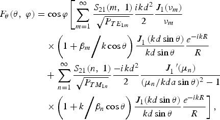
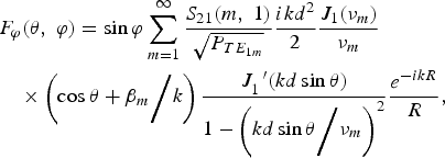
where, νm and μn are the roots of the Bessel equation J 1 and J 1′, respectively, d is the aperture radius, β m and β n denote propagation constant of TE1m mode and TM1n mode at the aperture, respectively. S21(m,1) and S21(n,1) represent the complex transmission coefficients obtained by mode matching theory. By using Eqs. (2) and (3), one can obtain E-plane and H-plane radiation pattern under the condition of φ = 0° and φ = 90°, respectively.
Cross-section of coaxial dual-band horn feed.

As mentioned above, this method can avoid solving the (complex) roots of the feed's characteristic equation, thus it is convenient to optimize the whole structure of the feed. The whole structure is divided into three parts to avoid using a great deal of time and a large mount of memory for simulation. First, the inner choke horn is designed to be flare angle controlled (Ying et al., Reference Ying, Kishk and Kidal1995), and the depth and width of coaxial corrugations are chosen as free parameters to be optimized to reduce the diffraction from the inner horn edge. Second, a circular waveguide with vertical corrugations plays an important part in the dual-band feed. Assuming the inner radius of the circular waveguide is a and the wavelength at 1.75 GHz is λ, under the condition of 1.6398 a < λ, higher order modes at low frequency stimulated at the aperture of the inner horn can be prohibited effectively. On the other hand, circular waveguide with vertical corrugations is equal to a TE11-to-HE11 mode converter at high frequency. Finally, the outer choke horn is designed in the same way as the inner choke horn to improve azimuthally symmetric output modes at low frequency, and it should avoid influencing the radiation pattern at high frequency simultaneously. To improve the power handling capacity of the feed, four coaxial corrugations are chosen to decrease the electric field strength at the aperture.
Dozens of different geometries have been analyzed to reach the final design, with the dimensions given in Table 2 and Figure 12, where the width of corrugations is d 1 and the thickness of ridges between them is d 2. Generally, the horn feed is always pumped into high vacuum state (less than 10−2 Pa) in application, and a spherical cover is utilized to airproof the horn feed. At last, the whole system structure is less than Φ75 cm × 60 cm.
Dimensions of the dual-band horn feed

The E-plane and H-plane of feed patterns at 1.75 GHz and 4.15 GHz are shown in Figure 13. Relative to the maximum gain possible, the L-band transmit gain is only lower by 0.5 dB than C-band. It is observed that E-plane and H-plane patterns of the feed are almost equal to each other in the illuminated area, while the feed is applied as a primary feed in an offset-shaped single-reflector antenna system. The power-handling capacity of the horn feed was also estimated by calculating the electric field strength on the axis of the feed, which is shown in Figure 14. According to the simulation, the input power is 1.0 Watt, and the origin of the z-axis is at the junction of the feed and mode converter. In the whole structure, the electric field strength is less than 17.34 V/cm at 1.75 GHz and 7.84 V/cm at 4.15 GHz, respectively. So it can be estimated that the power handling capacity in the horn feed reaches 3.33 GW at 1.75 GHz and 10 GW at 4.15 GHz, respectively (Baker & Schamiloglu, Reference Baker and Schamiloglu2001). In the near field, the electric field strength is less than 1.05 V/cm, and the breakdown threshold in atmosphere under the condition of short microwave duration is about 5 × 10⁴ V/cm, so the power breakdown threshold in this area is about (5 × 10⁴/1.05)2 = 2.3 GW. It means that the antenna breakdown will take place in the near field of the antenna. The power-handling capacity of the dual-band horn feed is about 2.3 GW.
(Color online) E- and H-plane feed patterns at 1.75 GHz (left) and 4.15GHz (right).

(Color online) Electric field along the axial (input power is 1 W).

The L-band and C-band return loss is shown in Figure 15. A simple discontinuity designed in coaxial waveguide was used to produce better than a −20 dB return loss at 1.75 GHz. If necessary, a more sophisticated matching technique could be used to improve the bandwidths. Around the operation frequency 4.15 GHz, return loss is better than −20 dB. Furthermore, the phase center of each band has been calculated from the radiation field, and it is located within z = 44.5±2.0 cm over the dual-band. It can be seen that the performance levels achieved by this new design technique are fairly high, which is especially significant for the higher performance of horn feeds in dual- or multi-band HPM applications.
(Color online) L-band (left) and C-band (right) return loss as a function of frequency.

CONCLUSIONS
This paper has presented a complete study of a novel incoherent power combining architecture including a dual-band horn feed and two feed line structures. It has shown that the azimuthally symmetric output modes (the TM01 circular waveguide mode and the TEM coaxial waveguide mode) can be interchanged effectively through the two feed lines, and a good far-field radiation pattern of each band has been achieved. Two types of feed lines have a similar conversion efficiency of about 98% and a bandwidth of about 10%, at 1.75 GHz and 4.15 GHz, respectively. Although bandwidth of the dual-band horn feed at L-band is not very good, it still provides an efficient approach to realize incoherent power combining of HPM sources. In addition, the radiation system is large enough for high power handling capacity, and experimental research is planned for the next step in order to make sure the sufficient power handling capacity. A more sophisticated matching technique need to be studied to improve the reflection characteristic of L-band. More detailed measurements and refinements in the operation of the architecture are on going, and future research includes the multi-band horn feed and theoretical design of feed lines with a high power handling capacity, according with the development trends of HPM technology.
ACKNOWLEDGMENTS
This work was supported by the National High Technology Research and Development Program of China. The authors wish to express gratitude to L. M. Li and H. J. Zhou for their discussions and help in revising the manuscript.



