Nomenclature
- ALM
-
actuator line model
- ASM
-
actuator surface model
- AoA
-
angle-of-attack
- BEMT
-
blade element momentum theory
- CFD
-
computational fluid dynamics
- DES
-
detached eddy simulation
- DoE
-
design of experiments
- DP
-
distributed propulsion
- EGO
-
efficient global optimisation
- GA
-
genetic algorithms
- GPR
-
Gaussian process regression
- LES
-
large-eddy simulation
- LHS
-
Latin hypercube sampling
- PSO
-
particle swarm optimisation
- RANS
-
Reynolds-averaged Navier–Stokes
- RMSE
-
root mean square error
- rVPM
-
reformulated vortex particle method
- UAV
-
unmanned aerial vehicle
- URANS
-
unsteady Reynolds-averaged Navier–Stokes
-
 $AR$
-
wing aspect ratio
-
$b$
-
wing span
-
$B$
-
number of blades
-
$c$
-
chord length
-
$C_D$
-
drag coefficient
-
$C_L$
-
lift coefficient
-
$C_Q$
-
torque coefficient
-
$C_T$
-
thrust coefficient
-
$c_d$
-
sectional drag coefficient
-
$c_l$
-
sectional lift coefficient
-
$E$
-
aerodynamic efficiency
-
$f_{min}$
-
best observed objective
-
$J$
-
advance ratio
-
$Ma_{tip}$
-
tip Mach number
-
$n$
-
number of spanwise elements
-
$R$
-
propeller radius
-
$R^2$
-
coefficient of determination
-
$Re_c$
-
chord-based Reynolds number
-
$S_{{\rm ref}}$
-
wing reference area
-
$U_{\infty }$
-
freestream velocity
-
$t_r$
-
taper ratio
-
$y^+$
-
dimensionless wall distance


Greek symbol
-
$\alpha$
-
angle-of-attack
-
$\gamma$
-
dihedral angle
-
$\eta$
-
propulsive efficiency
-
$\lambda$
-
sweep angle
-
$\mu$
-
dynamic viscosity
-
$\nu$
-
kernel smoothness parameter
-
$\phi$
-
probability density function
-
$\Phi$
-
cumulative distribution function
-
$\rho$
-
fluid density
-
$\sigma$
-
standard deviation
-
$\theta _{tip}$
-
twist tip angle
-
$\omega$
-
vorticity
-
$\xi$
-
exploration parameter


1.0 Introduction
The European Union aims to achieve climate neutrality by 2050. To meet this target, the aviation sector must accelerate the adoption of technological innovations that reduce environmental impact without compromising economic viability [Reference Fard, He, Huang and Cao1]. Distributed propulsion (DP) has emerged as a promising concept for enhancing both the aerodynamic efficiency and energy performance of next-generation aircraft. Increasing regulatory constraints on emissions and noise are accelerating the adoption of cleaner and more efficient propulsion concepts that support sustainable aviation initiatives. In this context, DP represents a significant paradigm shift: by decoupling thrust from a small number of centralised engines, it opens a broad design space and enables innovative configurations aimed at improving aerodynamic efficiency, reducing energy consumption and improving controllability. A notable example is the NASA X-57 Maxwell aircraft, designed to demonstrate efficiency gains enabled by an electric distributed propulsion system [Reference Clarke, Redifer, Papathakis and Samuel2]. The aerodynamic benefits associated with DP configurations are strongly governed by complex and inherently unsteady interactions between propeller wakes and lifting surfaces. Consequently, numerical simulation plays a central role in the analysis and design of DP systems. However, suitable computational tools for this task must simultaneously provide sufficient fidelity and computational efficiency to support iterative design and optimisation, particularly during the early conceptual design phase. Traditional approaches to DP analysis typically model the propeller using an actuator-disk representation based on momentum theory [Reference Qiao, Zhang and Barakos3–Reference Wang, Zhou, Fan and Guo5]. Other studies employ blade element momentum theory (BEMT), and have shown that gradient-based rotor design optimisation can be performed with very low computational cost [Reference Ning6, Reference Ordaz, Nielsen and Wang7]. While these methods are computationally efficient and well suited for preliminary assessments, they are inherently limited in their ability to capture detailed wake structures and unsteady effects. At the opposite end of the fidelity spectrum, high-resolution computational fluid dynamics (CFD) approaches based on Reynolds-averaged Navier–Stokes (RANS), unsteady RANS (URANS), large eddy simulation (LES) and detached eddy simulation (DES) can resolve these phenomena more accurately, but their high computational cost and reliance on complex mesh generation procedures often render them impractical for design-space exploration and optimisation studies [Reference Alvarez and Ning8–Reference Rossano and De Stefano10]. Moreover, mesh generation and adaptation remain major bottlenecks in mesh-based CFD workflows, requiring substantial user intervention and introducing additional sources of uncertainty and variability [Reference Lim, Lee, Lee and Yee11]. In recent years, meshless methods have received increasing attention due to their flexibility and their ability to handle complex, unstructured flow domains without grid generation. These methods are particularly well suited for problems involving large deformations, vortex-dominated flows or rapidly changing topologies, features frequently encountered in DP systems that are conventionally addressed using dynamic meshing techniques [Reference Bottigliero, Rossano and De Stefano12]. Additionally, their Lagrangian nature facilitates the accurate tracking of vortical structures [Reference Alvarez and Ning13], which is critical for understanding propeller-airframe interactions. Consequently, meshless numerical methods represent a promising paradigm for the aerodynamic analysis and optimisation of distributed propulsion systems, with the potential to significantly reduce computational cost [Reference Alvarez and Ning14].
In this study, a meshless framework based on the reformulated vortex particle method (rVPM) [Reference Alvarez and Ning13, Reference Alvarez15] is employed using the open-source solver FLOWUnsteady [16, Reference Alvarez, Mehr and Ning17]. The rVPM formulation enables the direct resolution of propeller-induced vorticity and its interaction with lifting surfaces, thereby overcoming the simplifying assumptions inherent to actuator-disk-based models while avoiding the computational overhead and meshing complexity associated with conventional grid-based CFD approaches. Moreover, the rVPM framework supports variable numerical fidelity within a unified modelling environment, allowing the level of resolution to be tailored to the objectives of the analysis, from rapid evaluations suitable for conceptual design studies to more resolved simulations capable of capturing dominant unsteady flow features. Previous validation studies have demonstrated that rVPM-based simulations can accurately reproduce key wake structures and integrated aerodynamic quantities [Reference Artoni, Paniccia, Sabatino and Guerrero18], with discrepancies on the order of a few percent relative to experimental measurements, while maintaining substantially lower computational requirements than fully resolved mesh-based CFD methods [Reference Alvarez and Ning14, Reference Alvarez, Mehr and Ning17].
The primary objective of this work is to assess the capability of an rVPM-based meshless computational framework to support purely aerodynamic optimisation of distributed-propulsion propeller-on-wing configurations. The analysis is intentionally restricted to aerodynamic performance in order to isolate the underlying aero-propulsive mechanisms associated with distributed propulsion and their interaction with wing geometry. This choice enables a clearer interpretation of the physical trends governing the optimised solutions, but it does not account for structural, mass or aeroelastic constraints. Accordingly, the configurations identified in this study should be regarded as aerodynamically optimal within the scope of the present formulation, whereas their practical feasibility must be established in a subsequent multi-disciplinary design framework. Within this scope, the innovative contribution of the present work lies in the application of a variable-fidelity, meshless rVPM framework to the systematic aerodynamic analysis and optimisation of propeller-wing configurations, enabling the efficient exploration of a multi-dimensional design space while retaining the ability to resolve key unsteady interaction phenomena. The rVPM-based framework is first validated against experimental measurements for an isolated propeller, demonstrating its ability to predict thrust, torque and propulsive efficiency with good accuracy. The APC 10
 $\times$
7 thin electric propeller [19] is selected as the reference case because extensive experimental data are available, enabling a rigorous assessment of the numerical model. In a second validation step, the methodology is assessed for a coupled wing-propeller configuration representative of the distributed-propulsion system considered in this study. The corresponding FLOWUnsteady predictions are compared with results obtained from a high-fidelity unsteady CFD simulation performed in OpenFOAM v12 [20], using a sliding-mesh formulation [Reference Farrell and Maddison21]. Following validation, a preliminary parametric investigation is conducted to identify a suitable baseline configuration for the optimisation study. A set of propeller-wing layouts is examined to evaluate the influence of propeller placement and rotation direction. No formal optimisation is carried out at this stage; instead, the configuration yielding the highest aerodynamic efficiency is selected as the reference layout. Starting from this baseline, an aerodynamic optimisation is performed over a design space defined by wing and propeller geometric parameters. The initial design space is explored through Latin hypercube sampling (LHS), which is used to generate a database of FLOWUnsteady evaluations. The optimisation is carried out within an efficient global optimisation (EGO) framework. The optimal configuration identified within the explored design space is then re-evaluated through a dedicated rVPM simulation, which provides a reference estimate of the aerodynamic performance of the optimised design.
2.0 Methodology
This section describes the meshless methodology employed in this study. First, the computational framework, based on the rVPM method as implemented in the FLOWUnsteady solver, is presented. The second part outlines the design-space exploration and optimisation strategy, including the design of experiments and the surrogate-based optimisation procedure.
2.1 CFD solver
FLOWUnsteady [Reference Alvarez, Mehr and Ning17] is an open-source, variable-fidelity aerodynamic framework implemented in the Julia programming language. It integrates several modelling approaches developed by the FLOW Lab at Brigham Young University, including the vortex lattice method (VLM), strip theory, blade-element models, three-dimensional panel methods and the rVPM [Reference Alvarez and Ning13, Reference Alvarez15], which constitutes the core of the present study.
The rVPM is a numerically stable formulation of the vortex particle method that solves the LES filtered incompressible Navier–Stokes equations in vorticity form using a Lagrangian approach, thereby avoiding the need for mesh generation [Reference Alvarez and Ning13, Reference Alvarez, Mehr and Ning17]. The governing equation for the filtered vorticity field is
 \begin{equation}{{\partial {{\bar \omega }_i}} \over {\partial t}} + {{\bar u}_j}{{\partial {{\bar \omega }_i}} \over {\partial {x_j}}} = {{\bar \omega }_j}{{\partial {{\bar u}_i}} \over {\partial {x_j}}} + \nu {\nabla ^2}{{\bar \omega }_i} - \frac{\partial T^{\prime}_{ij}}{\partial {x_j}} + {{\partial {T_{ij}}} \over {\partial {x_j}}},\end{equation}
where the overbar denotes spatial filtering and
 $T_{ij}$
represents the subfilter-scale (SFS) vorticity stress tensor, while
 ${E_{adv}} = \frac {\partial T^{\prime}_{ij}}{\partial {x_j}}$
and
 ${E_{str}} = {{\partial {T_{ij}}} \over {\partial {x_j}}}$
are the SFS vorticity advection and SFS vortex stretching, respectively. The divergence of the SFS terms accounts for enstrophy transfer between resolved and unresolved scales, which is a key mechanism governing the accuracy of LES-based vortex methods [Reference Alvarez15]. The filtered vorticity equation can be expressed in compact vector form as
 \begin{equation}{{d\bar\omega } \over {dt}} = (\bar\omega \cdot\nabla )\bar{\textbf{u}} + \nu {\nabla ^2}\bar\omega - {\textbf{\textit{E}}_{{\textrm{adv}}}} - {\textbf{\textit{E}}_{{\textrm{str}}}},\end{equation}
where the material derivative highlights the suitability of the vorticity formulation for a Lagrangian discretisation. In rVPM, the vorticity field is discretised using vortex particles whose positions are advected by the filtered velocity field, while particle strength and core size evolve according to conservation principles [Reference Alvarez and Ning13]. Unlike the classical vortex particle method, which assumes a constant particle core size, rVPM introduces an explicit evolution equation for this parameter, improving numerical stability and accuracy. To model subfilter-scale effects, rVPM employs an anisotropic vortex-stretching SFS model developed by Alvarez and Ning [Reference Alvarez and Ning13]. Unlike the standard Smagorinsky model, which assumes homogeneous isotropic turbulence and may introduce excessive dissipation, this formulation leverages vortex stretching as the primary mechanism for enstrophy transfer. As a result, it is particularly well suited for flows dominated by coherent vortical structures, such as propeller wakes. While the meshless, Lagrangian formulation is effective for resolving unbounded flows, the treatment of solid boundaries requires additional modelling. In FLOWUnsteady, wings and rotors are introduced through actuator-based approaches that impose boundary conditions and embed the associated vorticity in the LES domain [Reference Alvarez and Ning14]. Propellers are modelled using an actuator line model (ALM), whereas lifting surfaces are represented using an actuator surface model (ASM), which enforces a no-flow-through condition by imposing a zero-normal-velocity condition on the surface. Previous studies have shown that the ALM implementation in FLOWUnsteady accurately captures wake dynamics and unsteady aerodynamic effects, yielding results comparable to fully resolved blade simulations [Reference Troldborg, Zahle, Réthoré and Sorensen22, Reference Stokkermans, van Arnhem, Sinnige and Veldhuis23]. For example, under hover conditions, rVPM-based predictions deviate by less than 2% from experimental measurements [Reference Alvarez and Ning13, Reference Alvarez, Mehr and Ning17]. Furthermore, because rVPM is less constrained by the CFL-type time-step restrictions typical of mesh-based CFD solvers, the framework supports a wide range of numerical fidelities within a single unified environment, making it well suited for both early-stage design studies and more resolved aerodynamic analyses.
2.2 Design space exploration and optimisation methods
Following the validation of the numerical framework, the second part of this study focuses on the aerodynamic optimisation of the wing-propeller configuration. The primary objective is to identify design solutions that minimise the drag coefficient
 $C_D$
(measured in counts), while preserving the baseline lift coefficient by exploiting the geometric and aero-propulsive flexibility offered by distributed propulsion architectures. To explore the design space in a computationally efficient manner, a surrogate-based optimisation framework is adopted. The overall workflow, illustrated in Figure 1, proceeds as follows:
-
1. An LHS plan is generated in Python and exported as a parameter table.
-
2. Each sampled configuration is evaluated using the FLOWUnsteady solver, and the resulting aerodynamic coefficients are stored in a shared CSV database.
-
3. Candidate Kriging surrogate models are trained in Python using the input–output pairs contained in the database, and the most accurate formulation is selected.
-
4. The candidate surrogate models are assessed through leave-one-out and five-fold cross-validation in order to identify the best-performing model and verify whether its predictive accuracy is sufficient. If the resulting accuracy is not sufficient, the sampling plan is enriched.
-
5. A sequential infill strategy based on EGO proposes new candidate designs by maximising an acquisition function on the surrogate model. Each candidate configuration is evaluated with FLOWUnsteady and appended to the database, after which the surrogate model is retrained.
-
6. Once the infill process has converged, the global optimum is extracted from the final surrogate and subsequently validated through a confirmatory FLOWUnsteady simulation.
To enable a fully automated workflow, data exchange between the Python-based surrogate framework and the Julia-based solver is managed via a shared CSV database.
Workflow of the optimisation framework.

Figure 1. Long description
The flowchart outlines the steps involved in the optimization framework for distributed propulsion systems. The process begins with defining design variables and bounds. Next, an initial design of experiments (DOE) is generated, followed by high-fidelity computational fluid dynamics (CFD) evaluation. The results are stored in a simulation database. A Kriging surrogate model is then trained using the data from the simulation database. The model undergoes leave-one-out cross-validation (LOO-CV) to assess its performance based on R-squared (R²) and root mean square error (RMSE) metrics. If the R² value from LOO-CV meets or exceeds a specified threshold, the process proceeds to maximize the expected improvement (EI). If the EI is less than a certain value, the process moves to global surrogate optimization. The optimum design is then validated using FlowUnsteady, leading to the final optimized design. If the R² value does not meet the threshold, additional DOE points are added, and the process loops back to the high-fidelity CFD evaluation step.
2.2.1 Sampling scheme
The initial design of experiments (DoE) is generated using LHS [Reference Navid, Khalilarya and Abbasi24], a stratified sampling technique in which the range of each design variable is divided into equiprobable intervals per dimension, and one sample is drawn from each interval. This approach ensures uniform marginal coverage of the design space and promotes a well-dispersed distribution of samples in the multi-dimensional domain. To improve the space-filling properties of the DoE, an optimised LHS procedure is adopted [Reference Li, Lu, Xie and Yang25]. Specifically, multiple candidates for LHS are generated, and their quality is assessed using a discrepancy-based criterion that quantifies the uniformity of the sample distribution on the unit hypercube. A total of 100 LHS plans are evaluated, and the one exhibiting the minimum discrepancy is selected as the final DoE. The size of the database is chosen according to the guideline proposed by Loeppky et al. [Reference Loeppky, Sacks and Welch26], who recommend
 $N \geq 10d$
samples for the reliable construction of Kriging-based surrogate models, where
 $d$
is the number of design variables. In the present study,
 $d = 8$
shape design variables are considered, which yields a minimum recommended sample size of 80. On this basis, an initial database of 200 design points is generated. This sample size corresponds to 25 samples per dimension and is chosen in order to provide adequate coverage of the design space.
2.2.2 Kriging formulation
The surrogate modelling strategy adopted in this work is Kriging, also referred to as Gaussian process regression (GPR) [Reference Sacks, Welch, Mitchell and Wynn27, Reference Rasmussen and Williams28]. A key advantage of this approach is that, for any query point in the design space, it provides both a predicted mean and an associated prediction uncertainty. The mean represents the surrogate estimate of the aerodynamic response, whereas the uncertainty is exploited to guide the EGO infill strategy described in the following section. A comprehensive mathematical treatment of Kriging can be found in Forrester et al. [Reference Forrester, Keane and Bressloff29]. Several Kriging formulations are assessed in order to identify the surrogate model best suited to the present optimisation problem. The candidate models include isotropic (ISO) and automatic relevance determination (ARD) variants based on Matérn covariance kernels with
 $\nu = 3/2$
and
 $\nu = 5/2$
. In all cases, the covariance function is defined as the product of a constant kernel and the selected Matérn kernel, augmented by a white-noise term. Model assessment is based primarily on leave-one-out cross-validation (LOO-CV), which is widely regarded as a reliable diagnostic for Kriging surrogates trained on relatively small datasets [Reference Forrester, Keane and Bressloff29, Reference Toal30]. In the LOO-CV procedure, each sample is removed in turn, the model is trained on the remaining
 $N-1$
samples and the excluded observation is then predicted. From these predictions, the coefficient of determination
 $R^2_{{\rm LOO}}$
and the root mean square error (RMSE) are computed for each candidate model. As additional diagnostics, the in-sample coefficient of determination and the associated generalisation gap are also monitored. A shuffled five-fold cross-validation analysis is further performed as a robustness check. In the present implementation, the kernel hyperparameters, which control the overall amplitude, characteristic length scale, and noise level of the response surface, are estimated by maximising the log-marginal likelihood of the training data [Reference Rasmussen and Williams28]. Prior to model fitting, both the design variables and the response values are standardised to zero mean and unit variance. A nugget term is introduced through the white-noise kernel in order to improve the numerical conditioning of the covariance matrix and to account for residual numerical noise in the simulation data. The nugget amplitude is treated as an additional hyperparameter and is optimised jointly with the remaining kernel parameters through maximum-likelihood estimation. In addition, a small diagonal regularisation term is included to ensure the numerical stability of the Cholesky factorisation. Model selection is based primarily on
 $R^2_{{\rm LOO}}$
. When different kernels exhibit statistically indistinguishable LOO-CV performance, preference is given to the smoother Matérn-
 $5/2$
formulation and, secondarily, to the model with the smaller generalisation gap. Finally, the computational cost of each candidate surrogate is also monitored. Peak memory usage is estimated from a single model fit, whereas the reported wall-clock time refers to the cross-validation-based model-assessment stage. Since Kriging models require storage of the full
 $N \times N$
covariance matrix, memory usage scales as
 $\mathcal{O}(N^2)$
, while training cost scales cubically with the number of samples. For the dataset sizes considered in this work, surrogate construction does not represent a computational bottleneck within the overall optimisation workflow.
2.2.3 Sequential infill via EGO
The initial surrogate model may show limited accuracy in critical regions of the design space, particularly near the global optimum. To improve its performance, the surrogate is iteratively refined through a sequential infill strategy based on EGO [Reference Jones, Schonlau and Welch31].
The acquisition function adopted in this work is the expected improvement (EI), formulated for minimisation as
 \begin{equation}{ {{\textrm{EI}}({\textbf{x}})} { = ({\,f_{\min }} - {{\textbf{x}}_{avg}} - \xi ){\mkern 1mu} \Phi (Z) + \sigma ({\textbf{x}}){\mkern 1mu} \, \phi \, (Z),} } \end{equation}
 \begin{equation}Z = {{{f_{\min }} - {{\textbf{x}}_{avg}} - \xi } \over {\sigma ({\textbf{x}})}}.\end{equation}
where
 $f_{\min }$
is the best
 $C_D$
value observed so far,
 $\textbf{x}_{avg}$
and
 $\sigma (\textbf{x})$
denote the surrogate predictive mean and standard deviation at location
 $\textbf{x}$
,
 $\Phi$
and
 $\phi$
are the cumulative distribution and probability density functions of the standard normal distribution and
 $\xi \ge 0$
controls the exploration–exploitation trade-off. In the present work,
 $\xi = 0.01$
is adopted. The EI criterion balances the search between promising regions of the design space and areas characterised by large predictive uncertainty. Near existing training samples, the predictive variance becomes very small, and
 ${\textrm{EI}} \rightarrow 0$
, preventing redundant evaluations. Because the EI landscape is generally multi-modal, its maximisation is performed using differential evolution (DE) [Reference Storn and Price32], a population-based derivative-free optimiser.
The choice of DE as the optimisation algorithm was motivated by a trade-off between global search capability and computational cost. Population-based stochastic methods such as genetic algorithms (GA) and particle swarm optimisation (PSO) are widely used in aerodynamic design because of their higher probability of locating a global optimum compared to gradient-based methods [Reference Jahangirian and Shahrokhi33, Reference Huo, Liu, Chen, Chen and Wang34]. However, this advantage comes at the cost of a substantial number of function evaluations: for example, GA-based optimisation of a single inviscid aerofoil has been reported to require on the order of 1,000 simulations to achieve convergence [Reference Jahangirian and Shahrokhi33, Reference Huo, Liu, Chen, Chen and Wang34], a computational burden that becomes prohibitive as the dimensionality of the optimisation problem increases. Other comparative studies in the literature have shown that GA tends to outperform PSO in aerodynamic shape optimisation problems in terms of solution quality [Reference He, Liu and Liu35]. The resulting candidate design is evaluated with FLOWUnsteady, and the new observation is appended to the database. The surrogate model is then retrained on the updated dataset, allowing the predictive uncertainty to be reduced in the vicinity of the new sample and the acquisition landscape to shift toward unexplored regions. Before each infill iteration, the predictive accuracy of the surrogate is verified through the LOO-CV
 $R^2$
. Following Forrester et al. [Reference Forrester, Sóbester and Keane36], who suggest
 $R^2 \gt 0.8$
as indicative of good surrogate accuracy, a more conservative threshold of
 $R^2 = 0.95$
was adopted. If the threshold is not met, additional space-filling samples are introduced to improve the training dataset before resuming the EGO loop. The infill procedure terminates when the maximum EI falls below a threshold defined as a fraction of the observed
 $C_D$
range, indicating that further high-fidelity evaluations are unlikely to yield meaningful improvement.
2.2.4 Extraction of the surrogate optimum
Once the EGO infill procedure has converged, the minimum of the final Kriging response surface is extracted through a dedicated surrogate-optimisation stage. The surrogate model is inexpensive to evaluate, so extensive searches of the bounded design space can be carried out at negligible computational cost relative to simulation-based evaluations. A DE algorithm is first employed to perform a global, derivative-free search of the surrogate landscape [Reference Storn and Price32]. Owing to its population-based formulation and its ability to explore potentially multi-modal response surfaces, DE is well suited to identifying the most promising regions of the design space. To complement the global search, local optimisation is also carried out using the Limited-memory Broyden–Fletcher–Goldfarb–Shanno with Bound constraints (L-BFGS-B) quasi-Newton method [Reference Byrd, Lu, Nocedal and Zhu37], both from a single initial guess located at the centre of the design domain and from multiple random starting points. This comparison is used to assess the sensitivity of the solution to initialisation and to reduce the risk of retaining a suboptimal local minimum. In addition, the DE solution is refined through a separate L-BFGS-B polishing step. The candidate optima obtained from the different optimisation strategies are then compared. The final configuration identified from the surrogate optimisation is then retained for subsequent re-evaluation using FLOWUnsteady, in order to verify that the surrogate-based prediction is consistent with the underlying aerodynamic response.
3.0 Computational setup
This section presents the numerical setup employed for the simulations conducted in this study.
The propeller considered in this work is the APC 10
 $\times$
7 thin electric model, which is widely used in the literature and for which extensive experimental and numerical data are available [19]. A detailed description of its geometry and the associated simulation parameters can be found in Section 3.1, while Section 3.2 presents the baseline wing–propeller configuration, including the propeller placement, the overall aerodynamic layout and the numerical settings adopted consistently across all simulations.
3.1 Isolated propeller
3.1.1 Geometry
The test case adopted in this study focuses on the APC 10
 $\times$
7 propeller [19], a commonly used model in small-scale UAV applications. This two-blade fixed-pitch propeller has a diameter of 0.254 m and serves as the baseline for the aerodynamic optimisation studies discussed in the following sections. Figure 2a shows an isometric rendering of the propeller geometry, while Figure 2b presents the chord length and blade twist angle distributions along the normalised radial position
 $(r/R)$
of the blade. These geometric parameters directly influence the aerodynamic loading and performance of the propeller and are used as input for the actuator line model implemented in FLOWUnsteady.
Geometric details - APC 10
 $\times$
7 [19].

3.1.2 Simulation parameters
The air properties were assumed constant, with a density
 $\rho \approx 1.225$
kg/m
 $^3$
and dynamic viscosity
 $\mu \approx 1.81 \times 10^{-5}$
Pa
 $\cdot$
s. The rotational speed of the propeller was set to 4,000, 8,000 and 20,000 RPM, while the advance ratio
 $ J$
varied from 0 to 1 in increments of 0.05. These settings were selected to replicate the operating conditions provided by the propeller manufacturer, enabling a direct comparison between the numerical results and the reference data [39]. The simulations were conducted for a total of five revolutions, with each revolution comprising 36 timesteps, resulting in a total of 180 timesteps. Each blade was discretised using
 $ n = 20$
spanwise elements, with a geometric expansion factor of
 $ r = 0.1$
applied to refine the element spacing. This approach typically concentrates the resolution near the blade root or tip, depending on the implementation. In the rVPM scheme utilised within the FLOWUnsteady framework, vorticity is shed from lifting surfaces based on both steady and unsteady aerodynamic loading. For the present simulations, four particles were shed per time step, with unsteady shedding enabled and a threshold for circulation fluctuation set at 0.001. The number of particles shed per time step and unsteady shedding threshold were selected on the basis of the numerical convergence study presented in Section 5.2, in which three fidelity levels were assessed by varying the number of shed particles per step from 2 to 5. The circulation fluctuation threshold of 0.001 follows the recommended practice for rVPM-based simulations of rotor-wing configurations [Reference Alvarez and Ning13, Reference Alvarez and Ning14]. This criterion activated vorticity shedding whenever the relative change in circulation exceeded the specified limit, while starting vortex shedding was disabled. The maximum number of particles was estimated using the following formula [Reference Alvarez and Ning14]:
 \begin{align} \textit {max particles} = \left [(2n + 1)B\right ] \cdot n_{\text{steps}} \cdot p_{\text{per}\ \text{step}} + 1 \\[-10pt] \nonumber \end{align}
where
 $ n$
is the number of spanwise panels per blade,
 $ B$
is the number of blades,
 $ n_{\textrm{steps}}$
is the total number of time steps and
 $ p_{\textrm{per}\ \textrm{step}}$
is the number of particles shed per step. Although high Reynolds numbers associated with open-rotor configurations often render viscous diffusion negligible in the far wake, viscous modelling was retained for completeness. Viscous diffusion was handled using the core spreading method, combined with a radial basis function interpolation scheme for spatial adaptation, as developed by Barba et al. [Reference Barba, Leonard and Allen40–Reference Torres and Barba42]. The governing equations were integrated in time using a low-storage third-order Runge-Kutta method [Reference Williamson43]. To capture the turbulent dissipation of vorticity in the wake, an SFS model is employed. Specifically, the simulations utilised a two-level dynamic model with backscatter clipping. This model dynamically evaluated the SFS stress contribution based on a localised enstrophy balance and suppressed unphysical energy backscatter through a clipping condition [Reference Alvarez and Ning13]. Such measures are essential for ensuring numerical stability and physical consistency in regions where vortex stretching is the dominant turbulence mechanism. While alternative SFS models were considered, the two-level approach offered an optimal balance between robustness and computational cost for the current configuration. The selected settings correspond to a mid–high level of numerical fidelity [Reference Alvarez15], ensuring a good balance between computational cost and solution accuracy.
Geometric parameters for the baseline configuration

Table 1. Long description
A table with two columns and six rows. The first column is labeled ‘Parameter’ and the second column is labeled ‘Value’. The table lists the following parameters and their corresponding values: Wing span, 11.43 meters; Wing aspect ratio, 8.78; Wing taper ratio, 0.70; Wing area, 14.88 square meters; Propeller radius, 0.55 meters; Twist tip, 0 degrees.
Illustration of the wing baseline configuration with four APC 10
 $\times$
7 propellers positioned along the span. Geometric parameters are summarised in Table 1.

3.2 Distributed auxiliary propellers
3.2.1 Baseline configuration
For the propeller-on-wing simulations, the wing is modelled as a rigid structure with four propellers positioned along the span, as illustrated in Figure 3 and summarised in Table 1. The wing geometry is inspired by the Tecnam P2006, providing a representative baseline for light aircraft configurations, and has been widely adopted as a reference configuration [Reference Andrés, Van, Doll and Pastor44]. All simulations are conducted at a fixed angle-of-attack (AOA) of
 $ 4^\circ$
. The geometric parameters of the wing are summarised in Table 1.
Prior to the DoE, a preliminary analysis was conducted to evaluate the influence of propeller installation and rotation configuration on the overall aerodynamic performance of the distributed propulsion system. Two propulsion layouts were considered: a tractor configuration, with the propellers mounted upstream of the wing, and a pusher configuration, with the propellers located downstream of the wing. Both layouts employed four APC Thin Electric
 $10\times 7$
propellers [19] distributed along the wing span.
The propeller radius adopted in the wing-propeller simulations (
 $R = 0.55$
m) corresponds to a geometric scaling of the APC
 $10{\times }7$
reference propeller (
 $R = 0.127$
m) by a factor of approximately
 $4.3$
. This scaling was introduced to obtain a representative propeller-wing aerodynamic interaction at the light-aircraft scale of the Tecnam P2006 baseline configuration. The propulsive adequacy of the scaled configuration was then verified against the requirement of the reference aircraft, following the approach by Pacini [Reference Pacini, Prajapati, Duraisamy, Martins and He45]. Table 2 compares the thrust delivered by the baseline configuration with the thrust required by the Tecnam P2006 in the corresponding flight condition [Reference Pascale and Nicolosi46], showing that the propulsive requirement is met. The alternative strategy of downscaling the wing to a small-UAV scale was considered and discarded, as it would place the wing itself in a low-Reynolds-number regime dominated by laminar separation and transition effects, thereby introducing scale-dependent modelling uncertainty on the component of primary interest. The blade geometry was preserved in non-dimensional form from the original APC
 $10{\times }7$
design. However, at fixed operating conditions, this geometric scaling substantially modified the local section Reynolds number distribution along the blade. For this reason, the two-dimensional aerofoil polar tables used as input to the actuator line model were recomputed at Reynolds numbers representative of the scaled configuration. This ensured that the lift and drag coefficients (
 $c_l$
,
 $c_d$
) employed within the ALM were consistent with the local aerodynamic conditions at the operating scale.
Comparison of required and delivered thrust for the baseline configuration

Table 2. Long description
A table comparing the number of propellers, radius, and thrust for two aircraft configurations. The table has two rows and three columns. The columns are labeled ‘N. of propellers’, ‘Radius [m]’, and ‘Thrust [N]’. The first row represents the Tecnam P2006 configuration with 2 propellers, a radius of 0.86 meters, and a thrust of 1750 Newtons. The second row represents the Baseline configuration with 4 propellers, a radius of 0.55 meters, and a thrust of 1998 Newtons.
In the tractor configuration, the propellers were positioned at a streamwise distance equal to
 $0.35$
chord lengths upstream of the leading edge and at spanwise locations of
 $-0.731$
,
 $-0.279$
,
 $0.279$
, and
 $0.731$
, normalised by the semispan. The pusher configuration retained the same spanwise positions, while the propellers were shifted downstream by
 $0.35c$
relative to the trailing edge. For each layout, four propeller rotation configurations were considered, defined as follows:
-
• All inboard-up: all four propellers rotate such that the inboard blade moves upward
-
• All outboard-up: all four propellers rotate such that the outboard blade moves upward
-
• Alternating 1: the outboard propellers rotate clockwise and the inboard propellers rotate counter-clockwise
-
• Alternating 2: the outboard propellers rotate counter-clockwise and the inboard propellers rotate clockwise
In total, eight simulations were performed, covering all combinations of the two layouts and the four rotation configurations described above.
3.2.2 Operating conditions
The wing and propeller system was simulated at a freestream velocity of
 $U_{\infty } = 70$
m/s and an AoA of
 $4^\circ$
, while the propeller advance ratio was set to
 $J = 1.2$
, corresponding to typical cruise conditions for small-scale DP configurations [47]. Air properties were set to replicate atmospheric conditions at approximately 1800 m altitude, using the International Standard Atmosphere (ISA) model, yielding a density of
 $\rho \approx 1.027$
kg/m
 $^3$
. To fix the chord-based Reynolds number at a representative value for the wing boundary layer, the dynamic viscosity was adjusted to satisfy
 $Re_c \approx 10^6$
, with
 $\textrm{MAC} = S_{\textrm{ref}}/b \approx 1.30$
m, yielding a scaled value of
 $\mu \approx 9.35 \times 10^{-5}$
Pa
 $\cdot$
s. The viscosity scaling is adopted as a simplifying assumption to isolate the aerodynamic behaviour at a target Reynolds number, and its implications for the absolute accuracy of the predicted aerodynamic coefficients should be borne in mind when interpreting the results. The simulations consist of a total of 10 revolutions, each with 36 timesteps. The propeller blades were discretised using 12 spanwise elements with a geometric expansion factor of 0.1. The wing was discretised with 50 elements per semispan and a geometric expansion factor of 2.
Viscous diffusion was approximated with an inviscid scheme, whereas the dissipation of turbulent vorticity was modelled using the rVPM LES subfilter-scale approach. The temporal evolution of the flow field was advanced using an explicit Euler time-integration scheme. These particular settings correspond to a medium-fidelity setup, with
 $285,975$
vortex particles shed by the propellers during the simulation.
4.0 Design of experiments and geometry parametrisation
After selecting the baseline propeller configuration, a DoE approach was employed to investigate the aerodynamic response of the system across a range of geometric parameters. The objective was to create a representative and structured set of simulations that effectively captured the impact of each design variable on overall performance while minimising the number of evaluations required. The set of design variables included both propeller-specific and wing-related parameters, such as propeller radius, wingspan, aspect ratio, taper ratio and sweep, dihedral and tip twist angles. These parameters were varied within physically significant limits, ensuring coverage of the most relevant portions of the design space [Reference Andrés, Van, Doll and Pastor44, Reference Du, Liu, Shen, Wu, Zhang, Jiang and Zhong48, Reference Clarke, Erhard, Smart and Alonso49]. Using the LHS technique described in Section 2.2.1, a total of 200 design samples were generated. The optimisation problem was formulated with both inequality and equality constraints and can be expressed as
Minimise:
 \begin{equation*} C_D(\boldsymbol x, \alpha ) \end{equation*}
with respect to:
 \begin{equation*} x_i^{LB} \leq x_i \leq x_i^{UB}, \quad i = 1, \ldots , N, \end{equation*}
 \begin{align*} \alpha ^{LB} &\lt \alpha _i \lt \alpha ^{UB} \end{align*}
subject to:
 \begin{align*} C_L &= C_{L_{\textrm{baseline}}}, \end{align*}
 \begin{align*} R_{\textrm{propeller}} &\leq R_{\max },\quad\quad\quad \end{align*}
 \begin{align*} Ma_{\textrm{tip}} &= 0.55,\quad\quad \end{align*}
 \begin{align*} \ S_{\textrm{ref}} &= 14.88\,\textrm{m}^2. \end{align*}
Design variables and their corresponding lower and upper bounds

Table 3. Long description
A table with two columns and nine rows. The columns are labeled ‘Design parameter’ and ‘Bounds’, with sub-columns ‘Lower’ and ‘Upper’. The rows list various design parameters and their corresponding lower and upper bounds. Row 1: Propeller radius, 0.55, 0.86. Row 2: Wing span, 11.0, 13.5. Row 3: Taper ratio, 0.2, 0.8. Row 4: Sweep 1, 0, 20. Row 5: Sweep 2, 0, 30. Row 6: Dihedral 1, 0, 10. Row 7: Dihedral 2, 0, 5. Row 8: Twist tip, -8, 0. Row 9: Angle-of-attack, 3.5, 6.
Here,
 $\boldsymbol{x} = (x_1,\ldots ,x_N)$
denotes the vector of design variables, and
 $\alpha$
is included as an additional, independent design variable for each operating condition evaluated, following common practice in aerodynamic shape optimisation at fixed lift [Reference Kenway, Burdette and Martins50].
 $C_D(\boldsymbol{x}, \alpha )$
represents the drag coefficient to be minimised. The bounds
 $x_i^{LB}$
,
 $x_i^{UB}$
and
 $\alpha ^{LB}$
,
 $\alpha ^{UB}$
define the admissible ranges for the shape and AoA variables, respectively. The lift coefficient is constrained to match the baseline value in order to ensure aerodynamic performance comparable to the reference configuration. This equality constraint is enforced directly at the simulation level. In practice, this equality constraint is satisfied at the simulation level: for each configuration in the design of experiments,
 $\alpha$
is solved for within FLOWUnsteady such that the predicted lift coefficient converges to
 $C_{L_{\textrm{baseline}}}$
, which is equivalent to enforcing the constraint at the optimum of an inner sub-problem for
 $\alpha$
. This guarantees that all aerodynamic evaluations stored in the database correspond strictly to iso-lift conditions, so that the surrogate model is trained exclusively on constraint-satisfying designs. Additional geometric and operational constraints are imposed on the propeller radius and tip Mach number. In particular, the propeller radius (
 $R_{\textrm{propeller}}$
) is limited to prevent overlap between adjacent propellers. This constraint is automatically evaluated using the current value of
 $b$
for each sampled configuration, such that the admissible upper bound on
 $R_{\textrm{propeller}}$
varies accordingly across the design space. Furthermore, the tip Mach number is restricted to a value of 0.55. This threshold is selected in accordance with Clarke et al. [Reference Clarke, Erhard, Smart and Alonso49] to mitigate compressibility effects and reduce acoustic emissions. This constraint also ensures the validity of the Prandtl–Glauert compressibility correction applied to the two-dimensional blade-section aerodynamic characteristics within the actuator line model [Reference Alvarez and Ning51]. The lift coefficient is constrained to match the baseline value in order to ensure a fair aerodynamic comparison across all candidate configurations. This iso-lift formulation is consistent with standard practice in wing aerodynamic optimisation [Reference Chen, Lyu, Kenway and Martins52]. Finally, the wing reference area is held constant at
 $S_{\textrm{ref}} = 14.88$
m
 $^2$
throughout the optimisation by treating the root chord
 $c_{\textrm{root}}$
as a dependent variable, recomputed analytically for each configuration from the sampled values of wing span
 $b$
and taper ratio
 $t_r$
. This ensures full geometric consistency across all evaluated designs and guarantees that observed variations in
 $C_D$
are solely attributable to changes in the geometric and aero-propulsive parameters, rather than to differences in the effective lifting surface area. Table 3 summarises the range of each design parameter. The propeller radius and the wing span are varied to explore the aerodynamic coupling between the propulsive system and the lifting surface. The taper ratio is constrained to a minimum value of
 $0.2$
in order to preserve acceptable stall characteristics and avoid excessively tapered wing geometries [Reference Andrés, Van, Doll and Pastor44]. Additional geometric flexibility is introduced through the sweep and dihedral angles of two wing sections, allowing the optimiser to modify the wing aerodynamic loading and lateral stability characteristics. The corresponding bounds are selected to remain within physically realistic configurations while maintaining compatibility with typical light aircraft geometries [Reference Du, Liu, Shen, Wu, Zhang, Jiang and Zhong48]. Finally, the wing twist at the tip is included to control the spanwise lift distribution and delay tip stall. Negative twist values are considered in the design space to promote favourable aerodynamic loading near the wing tip. The bounds were selected to ensure physically realistic aircraft geometries while providing sufficient design freedom for the optimisation process.
It is worth clarifying how these requirements are accounted for within the surrogate-based infill strategy described in Section 2. The wing reference area is eliminated by re-parametrisation, the root chord being recomputed analytically for each configuration from the sampled span and taper ratio, so that
 $S_{\textrm{ref}}$
is satisfied identically. The lift coefficient equality is eliminated through an inner sub-problem, in which the AoA is determined for each configuration by iterating within FLOWUnsteady until
 $C_L = C_{L,\textrm{baseline}}$
: every aerodynamic evaluation is therefore iso-lift by construction. The blade tip Mach number is invariant with respect to the design variables, since the advance ratio is held constant and the rotational speed scales inversely with the propeller radius; it consequently excludes no region of the admissible domain. The propeller radius limit, introduced to prevent overlap between adjacent propellers, is thus the only requirement that actually restricts the design space; its upper bound has been set to the most conservative value admitted by the lower end of the span range, so that no overlap can occur anywhere in the domain. The feasible set therefore coincides with the box-constrained domain defined by the variable bounds reported in Table 3. The same bounds are employed at both stages of the procedure: they define the domain of the initial LHS and are passed unchanged as the search domain of the differential-evolution algorithm that maximises the expected improvement. No candidate lying outside these bounds can be generated at any stage of the optimisation. Feasibility is hence enforced throughout the infill process in an exact rather than probabilistic manner: every candidate proposed by the acquisition function satisfies all four requirements by construction.
5.0 Results and discussion
5.1 Verification and validation
The proposed computational approach, as detailed in Section 2, was validated by comparing performance predictions from FLOWUnsteady with manufacturer-provided performance data [39]. The APC 10
 $\times$
7 thin electric propeller was simulated across a range of advance ratios at a fixed angular velocity, and the results were compared to the manufacturer’s data, as shown in Figure 4. The simulations successfully captured the general trends of all performance metrics, demonstrating good agreement with the reference data in both thrust coefficients and propulsive efficiency across a wide range of advance ratios. These findings confirm that the rVPM can accurately reproduce the fundamental aerodynamic characteristics of an isolated propeller, supporting its use for the early-stage design of DP systems.
The simulations provide substantial insights into the propeller’s aerodynamic performance across different RPM values. At lower RPM values, the model tends to slightly overestimate the thrust coefficient, suggesting that model refinements may be needed to improve accuracy at low RPM. At higher RPMs, however, the torque coefficient predictions align more closely with the manufacturer’s data, indicating the model’s robustness in capturing dynamic effects and complex flow patterns at elevated speeds. This is likely due to the rVPM’s strength in resolving vortex-dominated flows and helical wake structures without mesh distortion or numerical dissipation. Despite these discrepancies, the propulsive efficiency is consistently well predicted across all tested conditions, highlighting the model’s reliability in assessing overall performance. This aspect is particularly relevant for the design and optimisation of distributed propulsion systems, where robust performance metrics are essential for informed configuration and operational choices.
The coupled-configuration assessment considers a wing-propeller system in the all-inboard-up tractor mode. To ensure a consistent benchmark, identical geometry and operating conditions are adopted in both FLOWUnsteady and OpenFOAM v12 [20]. The OpenFOAM simulations are performed on a hexahedral mesh of approximately
 $10$
million cells, with
 $y^+ \lt 1$
on all wall surfaces. Propeller rotation is resolved through a sliding-mesh approach [Reference Farrell and Maddison21], while turbulence is modelled using a
 $k$
–
 $\omega$
DDES formulation [Reference Gritskevich, Garbaruk, Schütze and Menter53]. An additional OpenFOAM URANS
 $k$
–
 $\omega$
simulation is also considered to provide an intermediate level of modelling fidelity. The assessment is based on the time-averaged aerodynamic coefficients reported in Table 4, while the time evolution of
 $C_L$
and
 $C_D$
for both rVPM and CFD is also presented in Figure 5. FLOWUnsteady predicts
 ${\, \bar{\kern-2pt C}}_L = 0.3289$
and
 ${\, \bar{\kern-2pt C}}_D = 0.0151$
, while the OpenFOAM sliding-mesh
 $k$
–
 $\omega$
DDES simulation yields
 ${\, \bar{\kern-2pt C}}_L = 0.3737$
and
 ${\, \bar{\kern-2pt C}}_D = 0.0128$
. The OpenFOAM URANS
 $k$
–
 $\omega$
results,
 ${\, \bar{\kern-2pt C}}_L = 0.3607$
and
 ${\, \bar{\kern-2pt C}}_D = 0.0125$
, provide an intermediate reference between the lower- and higher-fidelity evaluations. Overall, the comparison shows that the three approaches provide a qualitatively consistent aerodynamic characterisation of the coupled configuration, while exhibiting the fidelity-dependent discrepancies inherent to each modelling approach. FLOWUnsteady reproduces the main flow features and performance trends with good agreement, supporting its use as a suitable tool for repeated evaluations within surrogate-based optimisation frameworks.
Comparison of the time-averaged aerodynamic coefficients predicted by FLOWUnsteady and OpenFOAM for the wing–propeller configuration in the all-inboard-up tractor mode

Table 4. Long description
A table comparing the time-averaged aerodynamic coefficients predicted by FLOWUnsteady and OpenFOAM for the wing-propeller configuration in the all-inboard-up tractor mode. The table has three columns and two rows. Column headers are Coefficient, FLOWUnsteady, OpenFOAM k-ω DDES, and OpenFOAM URANS k-ω. Row labels are C_L and C_D. Row 1: C_L, 0.3289, 0.3737, 0.3607. Row 2: C_D, 0.0151, 0.0128, 0.0125.
Comparison of propeller performance metrics – thrust coefficient (
 $C_T$
), torque coefficient (
 $C_Q$
) and efficiency (
 $\eta$
) – as functions of advance ratio for three rotational speeds: the first row corresponds to 4000 RPM, second and third row to 8000 RPM and 20000 RPM, respectively. Simulation results are compared with reference data [39] provided by the propeller manufacturer to validate the model’s accuracy.

5.2 Definition of DP baseline configuration
This section presents the results of a preliminary parametric analysis aimed at identifying the wing-propeller configuration that achieves the highest aerodynamic efficiency
 $\big(E = {{{C_L}} \over {{C_D}}}\big)$
among the configurations examined and that is subsequently adopted as the baseline for the optimisation study. In addition, a numerical convergence and resolution sensitivity study is performed to quantify the influence of the selected level of numerical fidelity on the predicted aerodynamic loads. Table 5 summarises the aerodynamic performance of the investigated configurations, comparing different propeller rotation directions and installation layouts, including both tractor and pusher arrangements. The preliminary assessment showed that the all-inboard-up configuration provided the highest aerodynamic efficiency and was thus adopted as the baseline configuration for the optimisation study. Compared to the most efficient pusher configuration, this arrangement provides an improvement in aerodynamic efficiency of approximately 10% under identical operating conditions.
Time-averaged aerodynamic force coefficients and efficiency (
 $E$
) for the propeller-wing configurations considered

Table 5. Long description
A table with six rows and four columns. The columns are labeled Configuration, C L, C D, and E. The rows are labeled with different configurations: Tractor mode Alternating 1, Tractor mode Alternating 2, Tractor mode All outboard up, Tractor mode All inboard up, Pusher mode Alternating 1, Pusher mode Alternating 2, Pusher mode All outboard up, and Pusher mode All inboard up. Each row lists values for C L, C D, and E. Notable trends include the highest efficiency (E) of 21.75 for the Tractor mode All inboard up configuration and the lowest efficiency (E) of 16.40 for the Pusher mode All inboard up configuration.
 $^{1}$
Outboard propeller rotating clockwise, inboard propeller rotating counter-clockwise.
 $^{2}$
Outboard propeller rotating counter-clockwise, inboard propeller rotating clockwise.
Time evolution of
 $C_L$
(left) and
 $C_D$
(right) for both rVPM and CFD.

Figure 6 presents the sectional lift and drag distributions along the wing span for different propeller rotation configurations in tractor mode. The influence of blade rotation on the spanwise lift distribution is particularly evident: configurations with tip propellers rotating in the inboard-up direction (specifically Configurations 2 and 4) demonstrate a noticeable increase in the sectional lift coefficient (
 $c_l$
) near the wingtip. This behaviour can be attributed to the direction of the swirl induced by the propeller blades. When the inboard blade moves upward, it generates a local upwash over the wingtip region, effectively increasing the local AoA and enhancing lift generation. In contrast, configurations with outboard-up rotation tend to induce downwash near the tips, reducing the local AoA and therefore the lift. These aerodynamic interactions are the result of the complex coupling between the propeller’s helical vortex wake and the bound circulation on the wing. Similar results were found by Clarke et al. [Reference Clarke, Erhard, Smart and Alonso49].
Simulation settings for different levels of fidelity

Table 6. Long description
A table comparing simulation settings for different levels of fidelity. The table has 6 rows and 4 columns, including the header row. The columns are labeled Low, Mid, and Mid-high. The row labels are N. of wing elements per semispan, N. of blade elements, Time steps per revolution, Particles shed per time step, Wake treatment, Particle overlap, and Resulting N. of particles. Row 1: N. of wing elements per semispan, 50, 50, 50. Row 2: N. of blade elements, 12, 12, 20. Row 3: Time steps per revolution, 36, 36, 36. Row 4: Particles shed per time step, 2, 5, 5. Row 5: Wake treatment, Particle overlap, 2.125/10, 2.125/10, 2.125/10. Row 6: Resulting N. of particles, 114,390, 285,975, 472,321.
Sectional lift and drag spanwise distribution for different propeller rotation configurations (tractor mode).

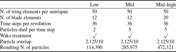
A numerical convergence study was conducted on the best-performing configuration identified in the preliminary analysis to determine an appropriate level of numerical resolution for the subsequent optimisation study. Three levels of numerical fidelity were considered, hereafter referred to as low, mid and mid–high fidelity, with the corresponding simulation settings summarised in Table 6. The results of the convergence assessment are presented in Figure 7, which report the spanwise distributions of the sectional lift and drag coefficients obtained at the three fidelity levels. Transitioning from the low- to the mid-fidelity configuration yields a substantial improvement in the prediction of both lift and drag distributions, allowing a more accurate representation of the primary aerodynamic features associated with the propeller–wing interaction. Increasing the resolution further to the mid–high fidelity level produces slightly sharper gradients, particularly in the sectional drag distribution in the vicinity of the propeller disks; however, the overall trends and dominant flow features remain largely unchanged with respect to the mid-fidelity results. These findings indicate that the mid-fidelity configuration provides an effective compromise between numerical accuracy and computational cost. Accordingly, this fidelity level was selected for all subsequent aerodynamic analyses presented in this work.
5.3 Optimisation results
5.3.1 Surrogate model selection and validation
Prior to surrogate training, the adequacy of the LHS-generated database was assessed through the computation of the Pearson coefficients: the correlation matrix shown in Figure 8 illustrates the linear relationships among the investigated design variables. All inter-parameter correlation coefficients remain small in magnitude, indicating the absence of strong linear dependencies within the sampled design space. This result suggests that the input parameters are approximately uncorrelated over the selected ranges, which is a desirable property for a well-constructed DoE.
In contrast, the correlations between the wing-tip twist angle (
 $\theta _{tip}$
) and
 $C_D$
, and between the taper ratio (
 $t_r$
) and
 $C_D$
, are considerably stronger (
 $r = 0.74$
and
 $r = 0.56$
, respectively). These values indicate a pronounced linear relationship between the design variables and the aerodynamic response. This observation is physically consistent with the dominant influence of these parameters on wing drag and agrees with the response surface trends that will be discussed in Section 5.3.2. Such limited inter-parameter coupling facilitates the interpretation of individual parameter effects and supports the robustness of subsequent sensitivity and regression analyses.
Predictive performance metrics for the four candidate Kriging surrogate models

Table 7. Long description
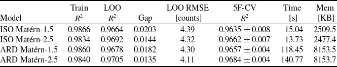
The table presents predictive performance metrics for four Kriging surrogate models. It has four rows and seven columns. The columns are labeled as Model, Train R squared, LOO R squared, LOO RMSE Gap, LOO RMSE counts, 5F-CV R squared, Time seconds, and Mem KB. The row labels are ISO Matérn-1.5, ISO Matérn-2.5, ARD Matérn-1.5, and ARD Matérn-2.5. Row 1: ISO Matérn-1.5, 0.9866, 0.9664, 0.0203, 4.39, 0.9635 ± 0.008, 15.04, 2509.5. Row 2: ISO Matérn-2.5, 0.9834, 0.9692, 0.0144, 4.32, 0.9662 ± 0.007, 13.73, 2477.4. Row 3: ARD Matérn-1.5, 0.9860, 0.9678, 0.0182, 4.30, 0.9657 ± 0.004, 118.45, 8153.5. Row 4: ARD Matérn-2.5, 0.9840, 0.9705, 0.0135, 4.11, 0.9684 ± 0.004, 140.77, 8153.7.
Sectional lift (left) and drag (right) coefficient along the span comparison for different levels of fidelity.

Correlation matrix of the shape design variables in the LHS database.

Once the reliability of the database had been established, the surrogate model candidates introduced in Section 2.2.2 were trained and assessed in order to identify the most suitable surrogate for the aerodynamic response. The corresponding performance metrics are reported in Table 7. For reference, the computations were performed on a workstation equipped with a 13th Gen Intel Core i9-13900, 32 cores, and 128 GB of RAM. Overall, the two isotropic kernels deliver the best predictive performance. In particular, ISO Matérn-2.5 achieves LOO
 $R^2$
among the isotropic formulations (0.9692) and LOO RMSE (4.32 counts), whereas ISO Matérn-1.5 follows very closely, with a LOO
 $R^2$
of 0.9664 and a LOO RMSE of 4.39 counts. For both models, the generalisation gap remains small (0.0144 and 0.0203, respectively), indicating a good balance between fitting accuracy and out-of-sample predictive capability. By contrast, the ARD formulations provide only a marginal improvement for the present 200-point database. ARD Matérn-1.5 yields a comparable overall performance, with a LOO
 $R^2$
of 0.9678, a LOO RMSE of 4.30 counts. ARD Matérn-2.5 provides the highest overall predictive accuracy, reaching a LOO
 $R^2$
of 0.9705 and a LOO RMSE of 4.11 counts; however, this improvement is limited and does not justify the increased computational cost. Although ARD Matérn-2.5 exhibits the smallest train-to-LOO gap (0.0135), both ARD models are associated with a substantially higher computational burden, requiring approximately 118–141 s of training time and about 8.15 MB of memory, compared with approximately 14–15 s and 2.5 MB for the isotropic counterparts. Since these timings were obtained on a 32-core workstation, they should be interpreted primarily as a relative measure for comparing the candidate models.
The five-fold cross-validation results are fully consistent with the LOO analysis. The isotropic models again achieve high mean scores, namely
 $0.9635 \pm 0.008$
for ISO Matérn-1.5 and
 $0.9662 \pm 0.007$
for ISO Matérn-2.5, with similarly low fold-to-fold variability. The ARD formulations achieve comparable results, with
 $0.9657 \pm 0.004$
for ARD Matérn-1.5 and
 $0.9684 \pm 0.004$
for ARD Matérn-2.5. This behaviour suggests that all models generalise robustly across the design space, rather than performing well only in localised regions. Given the negligible difference in predictive accuracy between the four kernels, the final selection is based on regularity considerations. From a physical standpoint, CFD-based aerodynamic response surfaces are expected to be at least twice continuously differentiable (
 $\textrm{C}^2$
). This level of smoothness is more consistent with the Matérn
 $\nu = 5/2$
kernel than with the
 $\nu = 3/2$
one. On this basis, ISO Matérn-2.5 was selected as the final surrogate model.
Figure 9 shows the predictive accuracy of the selected kernel through a parity plot of the LOO-CV predictions against the CFD-evaluated drag coefficients. The majority of the data points fall within the 10% error bound of the identity line across the full range of the dataset, with only a few outliers. This indicates that the ISO Matérn-5/2 surrogate generalises well across the sampled design space and can provide a reliable basis for the subsequent EGO infill and global optimisation.
Comparison of four surrogate-optimisation strategies applied to the converged ISO Matérn-2.5 response surface

Table 8. Long description
A table comparing four surrogate-optimisation strategies applied to the converged ISO Matrn-2.5 response surface. The table has four rows and four columns. Column headers are Method, C_p [counts], Time [s], Evals, and Mem [KB]. Row 1: Method, DE (global, no polish); C_p [counts], 27.77; Time [s], 9.037; Evals, 18000; Mem [KB], 184.4. Row 2: Method, DE + polish L-BFGS-B; C_p [counts], 27.76; Time [s], 9.046; Evals, 18018; Mem [KB], 184.4. Row 3: Method, L-BFGS-B 1 start (centre); C_p [counts], 80.39; Time [s], 0.009; Evals, 18; Mem [KB], 49.3. Row 4: Method, L-BFGS-B 50 multi-starts; C_p [counts], 52.10; Time [s], 0.499; Evals, 900; Mem [KB], 94.5.
Parity plot of LOO-CV predicted drag coefficient against CFD-evaluated values for the selected ISO Matérn-5/2 Kriging surrogate.

5.3.2 Surrogate optimisation and response surface analysis
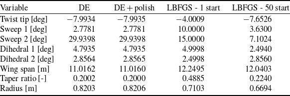
Four strategies were applied to extract the global minimum from the converged surrogate: pure DE, DE with L-BFGS-B polishing, 1- and 50-start L-BFGS-B. The performance metrics of the four strategies are summarised in Table 8, while a comparison of the optimisation results is presented in Table 9. The two DE-based strategies converge to the same solution, predicting a drag coefficient of 27.76–27.77 counts. Both variants identify an almost identical optimal design point, with negligible discrepancy. The subsequent L-BFGS-B polishing step does not yield any further improvement. As expected, the single-start L-BFGS-B initialised at the design-space centre converges to a substantially worse local solution, returning a predicted drag of 80.39 counts. This result is not surprising: a gradient-based method initialised at the centre of an eight-dimensional domain is prone to converging to suboptimal local minima [Reference Laurenceau, Meaux, Montagnac and Sagaut54]. The 50-start multi-start L-BFGS-B partially mitigates this limitation, with a best predicted value of 52.10 counts across 50 independent runs; however, it still fails to match the DE result. The combined evidence from these observations and results demonstrates that DE constitutes a more robust and reliable strategy for global minimum identification.
Comparison of optimisation results across different methods

Table 9. Long description
A table comparing optimization results across different methods. The table has four rows and six columns. The columns are labeled as Variable, DE, DE + polish, LBFGS - 1 start, and LBFGS - 50 start. The rows list different variables and their corresponding values for each method. Row 1: Twist tip [deg], 7.9934, 7.9935, 4.0009, 7.6526. Row 2: Sweep 1 [deg], 2.7781, 2.7781, 10.0000, 3.6300. Row 3: Sweep 2 [deg], 29.9398, 29.9398, 15.0000, 7.1024. Row 4: Dihedral 1 [deg], 4.7935, 4.7935, 4.9998, 2.4940. Row 5: Dihedral 2 [deg], 2.8564, 2.8565, 2.4998, 2.8560. Row 6: Wing span [m], 11.0162, 11.0160, 12.2495, 12.0403. Row 7: Taper ratio [-], 0.2002, 0.2000, 0.4885, 0.2240. Row 8: Radius [m], 0.8203, 0.8206, 0.7103, 0.6694.
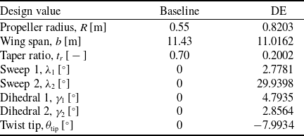
The DE optimal configuration is compared to the baseline in Table 10, while the response surfaces showing the relationship between variables are presented in Figure 10. Despite the boundary character of the optimum, the configuration predicted by the surrogate exhibits clear physical consistency. The physical reasoning behind these trends is further examined through the surrogate response surfaces presented in Figure 10.
Comparison between the baseline and optimised geometric parameters of the distributed propulsion configuration. The optimised setup corresponds to the differential solution minimising the drag coefficient

Table 10. Long description
A table comparing baseline and optimized geometric parameters for distributed propulsion configuration. The table has 8 rows and 3 columns. The columns are labeled ‘Design value’, ‘Baseline’, and ‘DE’. The rows are labeled with different design parameters and their corresponding values. Row 1: Propeller radius, Baseline: 0.55, DE: 0.8203. Row 2: Wing span, Baseline: 11.43, DE: 11.0162. Row 3: Taper ratio, Baseline: 0.70, DE: 0.2002. Row 4: Sweep 1, Baseline: 0, DE: 2.7781. Row 5: Sweep 2, Baseline: 0, DE: 29.9398. Row 6: Dihedral 1, Baseline: 0, DE: 4.7935. Row 7: Dihedral 2, Baseline: 0, DE: 2.8564. Row 8: Twist tip, Baseline: 0, DE: 7.9934.
To visualise the influence of individual design parameters, the response surfaces are extracted from the model by varying the selected variables while fixing all remaining parameters. These surfaces provide insight into key performance trends across the design space. Figure 10a shows the influence of wing tip twist and propeller radius on the drag coefficient. The results indicate that negative tip twist values consistently reduce
 $C_D$
, with the minimum drag occurring near the lower bound of the twist range (
 $\theta =-8^\circ$
). This behaviour is physically consistent with the role of washout in suppressing tip stall and redistributing spanwise loading toward the inboard sections, thereby reducing induced drag. The propeller radius exerts a comparatively weaker influence on
 $C_D$
; however, larger radii tend to produce slightly lower drag, reflecting the enhanced slipstream coverage over the wing and the associated increase in local dynamic pressure on the lifting surface. The response surface of drag coefficient as a function of taper ratio and wing span is illustrated in Figure 10b. As expected, the plot reveals a strong dependence of the drag coefficient on wing span. In particular, the results indicate a reduction in
 $C_D$
with decreasing wingspan. While this trend contrasts with the classical increase in induced drag associated with lower aspect ratios, it suggests that additional effects, such as a reduction in wetted surface area and corresponding viscous drag, as well as three-dimensional flow phenomena, play a significant role in the present configuration. The results also indicate that transitioning from a rectangular planform (taper ratio
 $\approx 1.0$
) to a more tapered configuration leads to a noticeable reduction in the drag coefficient
 $C_D$
, highlighting the aerodynamic efficiency gains associated with increased tapering. This trend is consistent with Prandtl’s classical argument that tapered wings offer aerodynamic advantages over wings with an almost rectangular planform [Reference Prandtl55–Reference Zhang, Wang, Liu and Wu57]. Moreover, as highlighted by Chen and Katz, tapered wings are generally preferred not only for their aerodynamic benefits but also for their favourable structural characteristics [Reference Chen and Katz58]. Figure 10c and d presents the response surfaces of the drag coefficient obtained by varying the sweep and dihedral angles at the root (
 $\lambda _1$
,
 $\gamma _1$
) and mid-span wing section (
 $\lambda _2$
,
 $\gamma _2$
). The results highlight a more subtle but non-negligible influence of sweep and dihedral on the aerodynamic efficiency. Overall, while their impact is smaller than that of other parameters, sweep and dihedral angles still produce measurable variations and should be considered when analysing or optimising wing geometry.
Response surfaces for the analysed shape design variables (1/2) and (2/2).

5.3.3 Validation of optimised shape
To verify the reliability of the surrogate prediction, the optimised configuration was re-evaluated through a dedicated mid-fidelity rVPM simulation using the same FLOWUnsteady setup described in Table 6. The simulation yielded a drag coefficient of 23.9 counts, compared with the surrogate prediction of 27.77 counts, corresponding to a relative discrepancy of approximately 16%. Relative to the baseline drag coefficient of 151 counts, the validated optimum represents a drag reduction of 84.2%, demonstrating the substantial aerodynamic benefit enabled by the combined effect of increased propeller radius, reduced taper ratio, negative tip twist and mid-span sweep within the distributed propulsion framework. The optimised configuration is compared with the baseline in Figure 11.
Vortex magnitude and sectional lift coefficient on the baseline (top) and optimised (bottom) configuration of the wing.

Figure 11. Long description
A diagram showing vortex magnitude and sectional lift coefficient on the baseline (top) and optimised (bottom) configuration of a wing. The diagram includes two panels. Panel A: The top panel shows the baseline configuration. The vortex magnitude is depicted with blue lines, and the sectional lift coefficient is represented by a color gradient from blue to red. Panel B: The bottom panel shows the optimised configuration. Similar to the top panel, the vortex magnitude is depicted with blue lines, and the sectional lift coefficient is represented by a color gradient from blue to red. The color gradient indicates the sectional lift coefficient, with blue representing lower values and red representing higher values. The vortex magnitude is shown with varying densities of blue lines, indicating the intensity of vortices.
6.0 Conclusions
This study presented an integrated framework for the aerodynamic analysis and optimisation of DP configurations using a meshless computational approach based on the rVPM method, implemented within the FLOWUnsteady open-source software. Validation results demonstrated that the rVPM framework reproduces the key aerodynamic characteristics of both an isolated propeller and a coupled wing-propeller system at substantially lower computational cost than conventional mesh-based CFD. The preliminary parametric analysis highlighted the critical role of propeller rotation direction on spanwise lift distribution, with the inboard-up tractor mode generating a beneficial upwash near the wingtip that enhances local lift generation, a mechanism that is absent in pusher configurations and outboard-up rotation modes. The surrogate-based optimisation revealed that the aerodynamic response surface is multi-modal in character, as evidenced by the failure of gradient-based multi-start approaches to match the solution identified by DE. This finding has practical implications for future optimisation studies in this design space, suggesting that population-based global optimisers should be preferred over local methods. The optimised configuration achieves a drag reduction of approximately
 $84\%$
relative to the baseline, driven primarily by increased propeller radius, negative tip twist, reduced taper ratio and increased outer-wing sweep, a combination that exploits both classical aerodynamic principles and the aero-propulsive coupling unique to distributed propulsion. It is important to contextualise this result in light of the boundary character of the identified optimum. Several design variables reach their bounds at the optimal configuration, strongly suggesting that the true absolute aerodynamic optimum may lie outside the explored design space. The bounds were selected to define a physically reasonable and computationally tractable design space for an early-stage study, and while the rationale for some bounds is clear, others are more difficult to justify on purely physical grounds. The reported drag reduction of
 $84\%$
should therefore be interpreted as the best performance achievable within the explored design space, and as an indication of the potential improvement that could be obtained with an expanded and more physically motivated parametrisation, rather than as the global aerodynamic optimum of the distributed propulsion configuration. The primary contribution of the present work is the demonstration that the rVPM-based surrogate framework can efficiently explore a multi-dimensional aero-propulsive design space and identify consistent performance trends at low computational cost, particularly during early-stage design studies where repeated high-fidelity evaluations must be balanced against computational constraints. The surrogate model assessment further demonstrated that the Matérn-2.5 formulation provides a suitable compromise between predictive accuracy, physical consistency and computational efficiency, enabling reliable optimisation of the aerodynamic response. Future work will focus on extending the framework to incorporate dynamic mission profiles, coupled propulsion–structure interactions, and multi-objective optimisation encompassing acoustic emissions and energy efficiency metrics.
Author contributions
Conceptualisation, R.B., V.R., and A.L.; methodology, R.B.; validation, R.B., V.R., and A.L.; investigation, R.B., V.R., and A.L.; resources, J.G. and G.D.; data curation, R.B., V.R., and A.L.; writing – original draft preparation, R.B.; writing – review and editing, V.R., A.L., J.G., and G.D.; visualisation, R.B., V.R., and A.L.; supervision, G.D. and J.G. All authors have read and agreed to the published version of the manuscript.
Financial support
The results presented in this work were developed as part of a project co-funded by Leonardo (contract LDO/INN/ P/0024998/24 dated 05-06-2024) with financial support from the PNRR - DM 630/2024.
Competing interests
The authors declare no conflicts of interest.


 ×
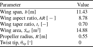
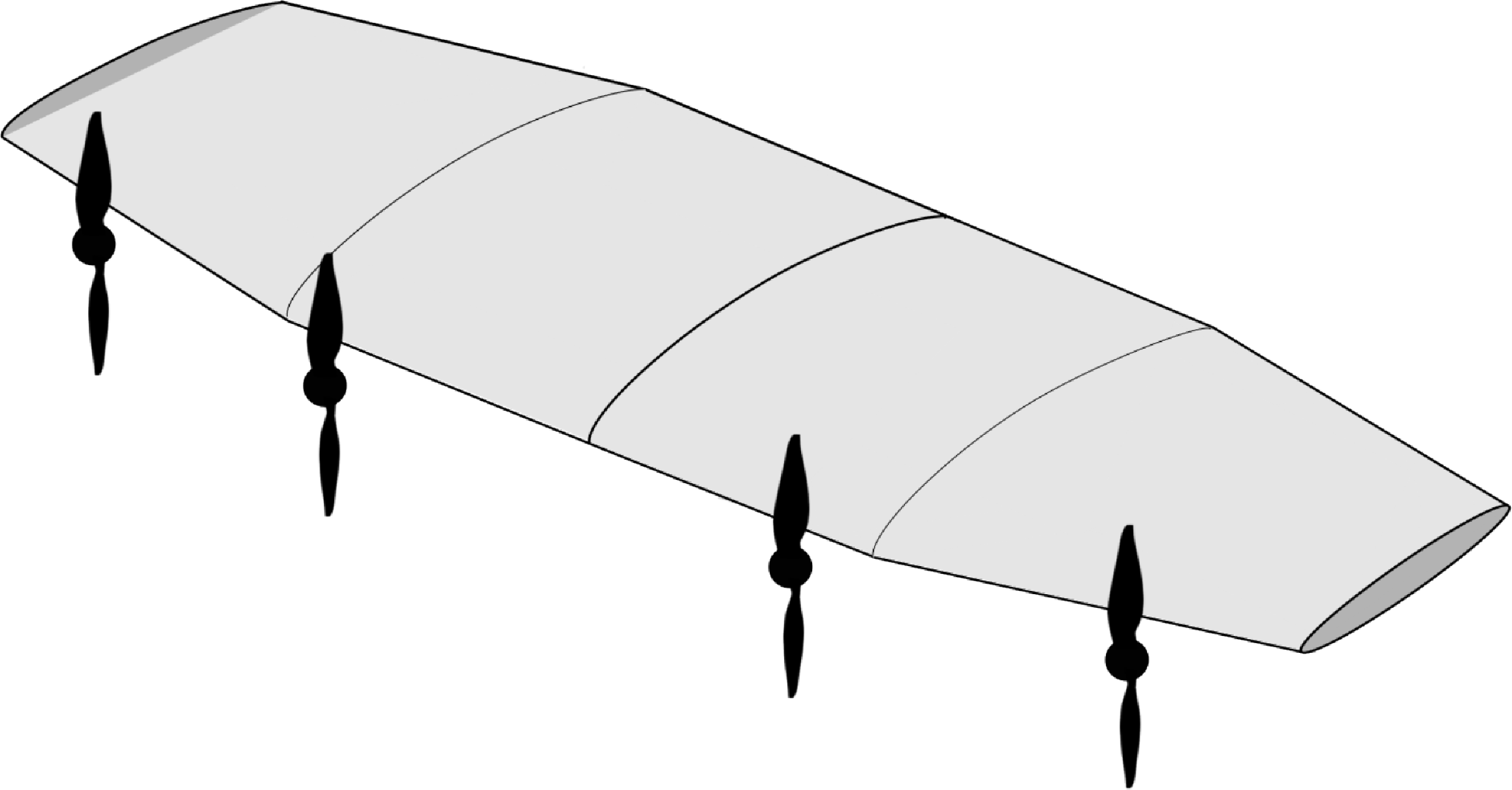
 ×

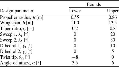


 CT
 CQ
 η
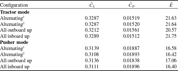
 E

 CL
 CD