1. Introduction
Wetting is a fundamental process in nature and our daily life (de Gennes Reference de Gennes1985; Bonn et al. Reference Bonn, Eggers, Indekeu, Meunier and Rolley2009). It is of critical importance in many industrial applications, e.g. coating, printing, chemical engineering, oil industry, etc. The wetting property is mainly characterized by the contact angle between the liquid–vapour interface and the solid surface. When a liquid drop is in equilibrium on a homogeneous smooth surface, the contact angle is described by the famous Young's equation (Young Reference Young1805). The equilibrium contact angle, also named Young's angle, depends on the surface tensions and reflects the material properties of the substrate. However, the real surface is usually neither homogeneous nor smooth and the chemical and geometric inhomogeneity may affect the wetting property dramatically. This makes the wetting phenomena very complicated in real applications, especially for dynamic problems.
For a liquid drop on an inhomogeneous surface, the apparent contact angle is usually different from the microscopic contact angle near the contact line even in equilibrium state. The equilibrium state of a droplet is determined by minimizing the total free energy of the system. When a global minimum is obtained, the apparent contact angle of a liquid can be described either by the Wenzel equation (Wenzel Reference Wenzel1936) or by the Cassie–Baxter equation (Cassie & Baxter Reference Cassie and Baxter1944). In reality, there exist many local minimizers that cannot be described by the two equations (cf. Gao & McCarthy Reference Gao and McCarthy2007; Marmur & Bittoun Reference Marmur and Bittoun2009). One can observe many equilibrium contact angles in experiments. The largest contact angle is called the advancing contact angle and the smallest one is the receding contact angle. The difference between the advancing and the receding angles is usually referred to the (static) contact angle hysteresis (CAH).
The static CAH has been studied a lot in the literature (see e.g. Johnson & Dettre Reference Johnson and Dettre1964; Neumann & Good Reference Neumann and Good1972; Cox Reference Cox1983; Joanny & De Gennes Reference Joanny and De Gennes1984; Schwartz & Garoff Reference Schwartz and Garoff1985; Extrand Reference Extrand2002; Priest, Sedev & Ralston Reference Priest, Sedev and Ralston2007; Whyman, Bormashenko & Stein Reference Whyman, Bormashenko and Stein2008 among many others). For a two-dimensional problem, the contact line is reduced to a point. When the surface is chemically composed of two or more materials with different Young's angles, it is found that the advancing contact angle is equal to the largest Young's angle in the system and the receding contact angle equals the smallest Young's angle (see Johnson & Dettre Reference Johnson and Dettre1964; Xu & Wang Reference Xu and Wang2011). For a three-dimensional problem, the situation becomes more complicated. The CAH due to a single defect on a homogeneous solid surface was analysed in Joanny & De Gennes (Reference Joanny and De Gennes1984). The analysis can be generalized to surfaces with dilute defects. Recently, some modified Wenzel and Cassie equations have been proposed to characterize quantitatively the local equilibrium contact angle and the CAH in Choi et al. (Reference Choi, Tuteja, Mabry, Cohen and McKinley2009), Raj et al. (Reference Raj, Enright, Zhu, Adera and Wang2012), Xu & Wang (Reference Xu and Wang2013) and Xu (Reference Xu2016). By these equations, the apparent contact angle can be computed once the position of the contact line is given. However, since the actual position of a contact line usually depends on the dynamic process (see Iliev, Pesheva & Iliev Reference Iliev, Pesheva and Iliev2018), we need study the dynamic wetting problem for real applications.
Dynamic wetting is much more challenging than the static case due to the motion of the contact line, which is still an unsolved problem in fluid dynamics (see Pismen Reference Pismen2002; Blake Reference Blake2006; Snoeijer & Andreotti Reference Snoeijer and Andreotti2013; Sui, Ding & Spelt Reference Sui, Ding and Spelt2014). The standard no-slip boundary condition may lead to a non-physical non-integrable stress in the vicinity of the contact line (Huh & Scriven Reference Huh and Scriven1971; Dussan Reference Dussan1979). To cure this paradox, many models were developed. A natural way is to explicitly adopt the Navier slip boundary condition instead of the no-slip condition (Huh & Scriven Reference Huh and Scriven1971; Zhou & Sheng Reference Zhou and Sheng1990; Haley & Miksis Reference Haley and Miksis1991; Spelt Reference Spelt2005; Ren & E Reference Ren and E2007) or implicitly impose the slip effect by numerical methods (Renardy, Renardy & Li Reference Renardy, Renardy and Li2001; Marmottant & Villermaux Reference Marmottant and Villermaux2004). Some other approaches include: to assume a precursor thin film and a disjoining pressure (Schwartz & Eley Reference Schwartz and Eley1998; Pismen & Pomeau Reference Pismen and Pomeau2000; Eggers Reference Eggers2005); to introduce a new thermodynamics for surfaces (Shikhmurzaev Reference Shikhmurzaev1993); to treat the moving contact line as a thermally activated process (Blake Reference Blake2006; Seveno et al. Reference Seveno, Vaillant, Rioboo, Adao, Conti and De Coninck2009; Blake & De Coninck Reference Blake and De Coninck2011); to use a diffuse interface model for moving contact lines (Gurtin, Polignone & Vinals Reference Gurtin, Polignone and Vinals1996; Seppecher Reference Seppecher1996; Jacqmin Reference Jacqmin2000; Qian, Wang & Sheng Reference Qian, Wang and Sheng2003; Yue & Feng Reference Yue and Feng2011), etc. Most of these models can be regarded as microscopic models for moving contact lines, due to the existence of very small parameters, e.g. the slip length and the diffuse interface thickness, etc. It is very expensive to use them in quantitative numerical simulations for dynamic wetting problems, unless the characteristic size of the problem is very small (Gao & Wang Reference Gao and Wang2012; Sui et al. Reference Sui, Ding and Spelt2014).
To simulate the macroscopic wetting problems efficiently, various effective models have been proposed. One important model is the so-called Cox model developed in Cox (Reference Cox1986) for viscous flows. The relation between the (macroscopic) apparent contact angle and the contact line velocity (characterized by the capillary number) is derived by matched expansions and asymptotic analysis. The model was further validated and developed in Sui & Spelt (Reference Sui and Spelt2013b) and Sibley, Nold & Kalliadasis (Reference Sibley, Nold and Kalliadasis2015a) and generalized in Ren, Trinh & E (Reference Ren, Trinh and E2015) and Zhang & Ren (Reference Zhang and Ren2019) for distinguished limits in different time regimes. In real simulations, one can use the macroscopic model directly and there is no need to resolve the microscopic slip region in the vicinity of the contact line. This improves significantly the efficiency of the numerical methods and makes it possible to quantitatively simulate some macroscopic moving contact line problems (Sui & Spelt Reference Sui and Spelt2013a).
To study the dynamic CAH, one needs to consider the moving contact line problems on (either geometrically or chemically) inhomogeneous surfaces. The problem has been studied theoretically in Raphael & de Gennes (Reference Raphael and de Gennes1989) and Joanny & Robbins (Reference Joanny and Robbins1990) for the single defect case. For the moving contact line problems with chemically patterned substrates, theoretical study is more difficult. Direct numerical simulations in two dimensions have been done in Wang, Qian & Sheng (Reference Wang, Qian and Sheng2008) and Ren & E (Reference Ren and E2011). In these simulations, they adopted some standard microscopic moving contact line models where the inhomogeneity of the substrates are described explicitly in the boundary conditions. The stick-slip behaviour of the contact lines was observed. The CAH was also observed when the period of the chemical pattern is small. The main challenge in direct simulations is that the computational complexity is very large in order to resolve the microscopic inhomogeneity. Besides direct simulations, more studies were done by using phenomenological CAH models (Dupont & Legendre Reference Dupont and Legendre2010; Yue Reference Yue2020; Zhang & Yue Reference Zhang and Yue2020), where the advancing and receding contact angles were given a priori and the contact line cannot move unless the dynamic contact angle was beyond the interval bounded by the two angles. The advancing and receding contact angles in these models are effective parameters. In general, it is not clear how the parameters are related to the chemical inhomogeneity of the substrates.
More recently, some experimental results on the dynamic CAH were presented in Guan et al. (Reference Guan, Wang, Charlaix and Tong2016a,Reference Guan, Wang, Charlaix and Tongb). They showed many interesting properties on the dynamic advancing and receding contact angles. Both the advancing and receding contact angles can change with the increase of the contact line velocity. The dependence of the contact angles on the velocity is quite complicated. Sometimes it seems symmetric while it can be very asymmetric in other cases. The asymmetric dependence is partially understood from the distributions of the chemical patterns (see Xu, Zhao & Wang Reference Xu, Zhao and Wang2019; Xu & Wang Reference Xu and Wang2020). But there is still a lack of complete understanding of all the experimental results.
The motivation of the work is twofold. Firstly, we would like to develop an averaged Cox-type boundary condition for moving contact lines on inhomogeneous surfaces. The boundary condition characterizes quantitatively how the macroscopic advancing and receding angles depend on the microscopic inhomogeneity of the substrates. With this condition, a macroscopic model may be developed for dynamic CAH. Secondly, we would also like to have more theoretical understanding of the complicated phenomena of dynamic CAH in recent experiments in Guan et al. (Reference Guan, Wang, Charlaix and Tong2016a,Reference Guan, Wang, Charlaix and Tongb).
For these purposes, we conduct our study in two steps. First, we derive a simplified Cox-type boundary condition for moving contact lines on general surfaces. The main tool here is to use the Onsager variational principle as an approximation tool. Recent studies showed that it is very useful for approximately modelling many complicated problems in viscous fluids and in soft matter (cf. Doi Reference Doi2015; Di, Xu & Doi Reference Di, Xu and Doi2016; Man & Doi Reference Man and Doi2016; Xu, Di & Doi Reference Xu, Di and Doi2016; Zhou & Doi Reference Zhou and Doi2018; Doi et al. Reference Doi, Zhou, Di and Xu2019; Guo et al. Reference Guo, Xu, Qian, Di, Doi and Tong2019; Xu & Wang Reference Xu and Wang2020). In this paper, we show that the principle can be used to derive a full sharp-interface model and a new simplified Cox-type boundary condition for moving contact lines. Without considering the contact line friction, the boundary condition is a first-order approximation for the original Cox's condition. With the condition, we can construct a reduced model for some interesting moving contact line problems, including the one for the experiments in Guan et al. (Reference Guan, Wang, Charlaix and Tong2016a,Reference Guan, Wang, Charlaix and Tongb). Second, we conduct an asymptotic analysis for the reduced model on chemically inhomogeneous substrates. By multiscale expansions, we derive an averaged dynamics for the contact angle and the contact point. This leads to an explicit formula for the averaged (in time) macroscopic dynamic contact angle on chemically inhomogeneous surfaces. The formula is a coarse-graining boundary condition for dynamic CAH. Our analysis is validated by numerical experiments. Furthermore, numerical examples show that the reduced model and the new boundary conditions can be used to understand the complicated behaviours of the apparent contact angles observed in the experiments in Guan et al. (Reference Guan, Wang, Charlaix and Tong2016a,Reference Guan, Wang, Charlaix and Tongb). All the main phenomena can be captured by the reduced model and described by the averaged formula.
Although the averaging analysis is conducted for a reduced model in the paper, the averaged boundary condition for dynamic CAH is quite general, since it does not depends on the specific set-up of the problem at all. The condition is a form of harmonic average of the simplified Cox-type boundary condition. The main result can also be generalized to the case where the original Cox's boundary condition applies. We expect that the formulae for the averaged macroscopic dynamic contact angles can be used as an effective boundary condition for the two-phase Navier–Stokes equation for moving contact lines on inhomogeneous surfaces. Although the analysis in this paper is restricted to two-dimensional problems, the main results can be used to understand some three-dimensional CAH problems, e.g. on an inhomogeneous surface with dilute defects. Nevertheless, quantitative descriptions for general three-dimensional problems are still challenging and will be left for future study.
The structure of the paper is as follows. In § 2, we introduce the derivations for a Cox-type boundary condition for moving contact lines in a variational approach. A reduced model is presented for some specific problems. In § 3, we do asymptotic analysis for the reduced model to derive the averaged dynamics on chemically inhomogeneous surfaces. Explicit formulae for the apparent dynamic contact angles are derived. In § 4, we discuss the generalization of our result to some other models. In § 5, we validate the asymptotic analysis numerically and make comparisons with experiments. Finally, we give some concluding remarks in § 6.
2. Variational derivation for moving contact line models
In this section, we will derive a Cox-type boundary condition by a variational approach, which describes the dynamics of the apparent contact angle. The Cox-type boundary condition is employed to further reduce the model for two typical problems with moving contact lines. The reduced model acts as a model problem to study the dynamic CAH in the following sections.
2.1. Derivation of a Cox type model for the apparent contact angle
It is known that the two-phase flow has a multiscale property near moving contact lines. In general, the macroscopic contact angle is different from the microscopic one; see for example Cox (Reference Cox1986), where a dynamic boundary condition for the apparent contact angle was derived by matched asymptotic analysis. In the following, we derive a similar boundary condition by using the Onsager principle as an approximation tool. The derivation is much simpler but still captures the essential dynamics of the apparent contact angle. In Appendix A, we show that the variational principle can also be used to derive a full continuum model for moving contact lines.
As shown in figure 1, we separate the domain near the contact line into three different scales. The macroscopic region  $\varOmega$ has a characteristic length
 $L$. The microscopic region is of molecular scale with a characteristic length
 $l$. In the microscopic scale, the interaction between the liquid molecules and the solid molecules induces a friction of the contact line (Guo et al. Reference Guo, Gao, Xiong, Wang, Wang, Sheng and Tong2013). The mesoscopic region has a characteristic length
 $D\ll L$, but still much larger than the molecular scale
 $l$. In this region, the no-slip boundary condition is still a good approximation. The contact angle
 $\theta _a$ represents the apparent angle in macroscopic point of view.
The region near the moving contact point in different scalings( $l\ll D\ll L$).

We are interested in the contact line dynamics in the mesoscopic region. For this purpose, we analyse the system by using the Onsager principle as an approximation tool. We make the ansatz that the interface between the two fluids in this region can be approximated well by a straight line  $\tilde {\varGamma }$ which has a tilting angle equal to the macroscopic contact angle
 $\theta _a$. With this assumption, we can use the Onsager principle to derive a relation between the apparent contact angle
 $\theta _a$ and the contact line motion as follows.
We first calculate the rate of change in the total free energy of the system. Similar to (A1), the total approximate free energy  $\tilde {\mathcal {E}}$ is composed of three surface energies. The changing rate of the total interface energies with respect to the motion of the contact line is given by
 \begin{equation} \dot{\tilde{\mathcal{E}}}=\gamma(\cos\theta_a-\cos\theta_Y)v_{ct} + \int_{\tilde{\varGamma}} \gamma\kappa v_n \,{\rm d}s= \gamma(\cos\theta_a-\cos\theta_Y)v_{ct}. \end{equation}
Here γ is the fluid–fluid surface tension,  $v_{ct}$ is the contact line velocity,
 $\theta_Y$ is the Young's angle,
 $\kappa$ and
 $v_n$ are respectively the curvature and the normal velocity of the fluid–fluid interface; the second term disappears since the curvature is zero for a straight line. To use the Onsager principle for the open system, we need consider the work to the exterior region on the outer boundary,
 $\dot {\tilde {\mathcal {E}}}^{*}=-\int _{\tilde {\varGamma }_{out}} \boldsymbol {F}_{ext}\boldsymbol {\cdot } \boldsymbol {v}$, with
 $\boldsymbol {F}_{ext}$ being the external force. This is a higher-order term in comparison with
 $\dot {\tilde {\mathcal {E}}}$, since it is of order
 $|\boldsymbol {F}_{ext}| v_{ct} D$ with
 $D\ll L=O(1)$. We will ignore this term in the following calculations.
We now compute the energy dissipations in the wedge region as shown in figure 1 (right plot). The total energy dissipation is calculated approximately as
 \begin{equation} \tilde{\varPsi}={\xi}v_{ct}^{2}+\int_{\tilde\varOmega_A}{\dfrac{\mu_A}{4} |\boldsymbol{\nabla} \boldsymbol{v}+\boldsymbol{\nabla} \boldsymbol{v}^{\rm T}|^{2}} \,{{\rm d}\kern0.06em x}+\int_{\tilde\varOmega_B}{\dfrac{\mu_B}{4} |\boldsymbol{\nabla} \boldsymbol{v}+\boldsymbol{\nabla} \boldsymbol{v}^{\rm T}|^{2}} \,{{\rm d}\kern0.06em x}, \end{equation}
In the above formula,  $\tilde {\varOmega }_A$ and
 $\tilde {\varOmega }_B$ are the domains corresponding to liquids
 $A$ and
 $B$ in the mesoscopic region,
 $\mu_A$ and
 $\mu_B$ are respectively the viscosities of fluids A and B, and the superscript T stands for the transpose of a matrix. The contact line friction term
 ${\xi }v_{ct}^{2}$ is due to the dissipation in the microscopic region and
 $\xi$ is the friction coefficient. The velocity
 $\boldsymbol {v}$ can be obtained by solving the Stokes equations in wedge regions assuming the interface moving in a steady state. By careful calculations (see Appendix A), we can compute the energy dissipation function approximately
 \begin{equation} \tilde{\varPhi}=\dfrac{1}{2}\tilde{\varPsi}\approx \dfrac{1}{2}{\xi}v_{ct}^{2}+\dfrac{\mu_A |\ln\zeta|}{2\mathcal{F}(\theta_a,\lambda)}v_{ct}^{2}, \end{equation}
where the dimensionless parameter  $\zeta =D/l$ is the ratio between the mesoscopic size and the microscopic size, and
 \begin{align} &\mathcal{F}(\theta_a,\lambda)\nonumber\\ &\quad =\dfrac{\lambda(\theta_a^{2}-\sin^{2}\theta_a)({\rm \pi}-\theta_a+\sin\theta_a\cos\theta_a)+(({\rm \pi}-\theta_a)^{2}-\sin^{2}\theta_a)(\theta_a-\sin\theta_a\cos\theta_a)}{2\sin^{2}\theta_a\left(\lambda^{2}(\theta_a^{2}-\sin^{2}\theta_a) +2\lambda(\sin^{2}\theta_a+\theta_a({\rm \pi}-\theta_a))+(({\rm \pi}-\theta_a)^{2}-\sin^{2}\theta_a)\right) }, \end{align}
with  $\lambda ={\mu _B}/{\mu _A}$. The contact line friction can be understood from the molecular kinetics theory (Blake & Haynes Reference Blake and Haynes1969; Blake Reference Blake2006; Blake & De Coninck Reference Blake and De Coninck2011). Molecular dynamic simulations have been done in Johansson & Hess (Reference Johansson and Hess2018) to compute the friction coefficient. For a water–air interface on a clean glass substrate, the coefficient
 $\xi$ is measured directly in experiments in Guo et al. (Reference Guo, Gao, Xiong, Wang, Wang, Sheng and Tong2013), which is given by
 $\xi \approx (0.8\pm 0.2)\mu$. Notice that
 $\ln \zeta$ is generally chosen as a constant of order
 $10$ (in de Gennes, Brochard-Wyart & Quere (Reference de Gennes, Brochard-Wyart and Quere2003), it is chosen as
 $13.6$). Direct computations also show that
 $1/\mathcal {F}(\theta _a,\lambda )=O(1)$. In this case,
 $\xi$ can be regarded a small perturbation to the viscous friction coefficient and can be ignored. More detailed discussions on the contact line friction can be found in Duvivier, Blake & De Coninck (Reference Duvivier, Blake and De Coninck2013). It is found that the friction coefficient
 $\xi$ is proportional to the viscosity of the liquid and exponentially dependent on the strength of solid–liquid interactions. The value of
 $\xi$ can range over several magnitudes for various systems.
By using the Onsager principle, we minimize the Rayleighian  $\mathcal {R}=\tilde {\varPhi }+ \dot {\tilde {\mathcal {E}}}$ with respect to
 $v_{ct}$. This leads to an equation for
 $v_{ct}$
 \begin{equation} {\left(\xi+\dfrac{\mu_A |\ln\zeta|}{\mathcal{F}(\theta_a,\lambda)}\right)}v_{ct}={-}\gamma(\cos\theta_a-\cos\theta_Y). \end{equation}
This equation basically means that the local dissipative force (due to the contact line friction and the viscous dissipation) is balanced by the effective unbalanced Young's force, which is the dominant term in the driving force in the mesoscopic region. It gives a relation between the contact line velocity and the apparent contact angle  $\theta _a$. The relation (2.5) can be rewritten in a dimensionless form
 \begin{equation} \left(\alpha + \dfrac{|\ln\zeta|}{\mathcal{F}(\theta_a,\lambda)}\right)Ca={-}(\cos\theta_a-\cos\theta_Y), \end{equation}
where  $\alpha ={\xi }/{\mu _A}$ and
 $Ca={\mu _A v_{ct}}/{\gamma }$ is the capillary number. The equation takes into account both the viscous friction in the mesoscopic region and the microscopic friction in the vicinity of the contact line.
When the contact line friction is less important than the viscous dissipation, the first term in (2.6) can be ignored. Then the equation is reduced to
 \begin{equation} |\ln\zeta|Ca={-}\mathcal{F}(\theta_a,\lambda)(\cos\theta_a-\cos\theta_Y). \end{equation}
This is a Cox-type formula for the apparent contact angle and the capillary number of the contact line. Equation (2.7) is consistent with Cox's formula at leading order when  $Ca$ is small. This will be discussed as follows. We recall Cox's formula for small
 $Ca$
 \begin{equation} |\ln\zeta|Ca=\mathcal{K}(\theta_a,\lambda)-\mathcal{K}(\theta_Y,\lambda). \end{equation}
where
 \begin{align} &\mathcal{K}(\theta,\lambda)\nonumber\\ &\quad=\int_{0}^{\theta}\dfrac{\lambda(\beta^{2}-\sin^{2} \beta)({\rm \pi}-\beta+\sin \beta \cos \beta)+(({\rm \pi}-\beta)^{2}-\sin^{2} \beta)(\beta-\sin \beta \cos \beta)}{2\sin \beta \left( \lambda^{2}(\beta^{2}-\sin^{2} \beta) +2\lambda(\sin^{2} \beta+\beta({\rm \pi}-\beta)+({\rm \pi}-\beta)^{2}-\sin^{2} \beta)\right)}\,\mathrm{d}\beta,\nonumber\\ &\quad=\int_0^{\theta} \mathcal{F}(\beta,\lambda)\sin\beta\,\mathrm{d}\beta. \end{align}
A first-order approximation of Cox's formula leads to
 \begin{align} |\ln\zeta|Ca&=\int_{\theta_Y}^{\theta_a}\mathcal{F}(\beta,\lambda)\sin\beta\,\mathrm{d}\beta\nonumber\\ & \approx{-}\mathcal{F}(\theta_a,\lambda )(\cos\theta_a-\cos\theta_Y)+O((\theta_a-\theta_Y)^{2}). \end{align}
This implies that Cox's formula is consistent with our analysis by using the Onsager principle to leading order. The difference between the two formulae is illustrated in figure 2. We can see that their difference is small for the small capillary number case (e.g.  $Ca\leq 0.01$). When
 $Ca$ is large, the linear approximation of the interface in the mesoscopic region is not very accurate anymore. Then there is a larger difference between (2.7) and Cox's formula.
Comparison between Cox's formula and (2.7). Here, we choose  $\lambda =0$ and
 $\theta _Y=110^{\circ }$. Their difference is small for small capillary number (
 $Ca\sim O(10^{-2}$)).

Equation (2.6) can be regarded as a coarse-graining boundary condition for the two-phase Navier–Stokes equation in the macroscopic region  $\varOmega$. It gives a relation between the apparent contact angle and the contact line velocity. The results are similar to that in de Gennes et al. (Reference de Gennes, Brochard-Wyart and Quere2003). One can use (2.6) instead of the microscopic boundary conditions (e.g. (A14)) to avoid resolving the mesoscopic region by very fine meshes in numerical simulations.
2.2. Model problems
In some problems with small characteristic size, the energy dissipation in the mesoscopic region may dominate. Then one can derive a reduced model for such problems. One typical example is the spreading of a small droplet on hydrophilic surfaces which gives the so-called Tanner's law (Tanner Reference Tanner1979). Other examples can be found in de Gennes et al. (Reference de Gennes, Brochard-Wyart and Quere2003), Chan, Yang & Carlson (Reference Chan, Yang and Carlson2020) and Xu & Wang (Reference Xu and Wang2020). In the following, we will introduce two typical examples. Then we show that they can be described by a unified reduced model, which will be used to study the dynamic CAH in the next section.
Example 2.1 A moving contact line problem in a micro-channel.
In the example, we consider a contact line problem in microfluidics, which is similar to that considered in Joanny & De Gennes (Reference Joanny and De Gennes1984). As shown in figure 3, suppose that the two walls of a channel are moving at a velocity  $u_{wall}$. There is a bar on the left-hand side of the channel to keep the liquid from moving out. Suppose that the height
 $h_0$ of the channel is smaller than the capillary length. Then we could assume that the interface remains almost circular if the velocity
 $u_{wall}$ is small. Then, the position of the contact point is fully determined by the dynamic contact angle since the volume of the liquid is conserved.
Contact point motion in a micro-channel.

Suppose the volume of the liquid is  $V_0$. We suppose the left boundary of the liquid domain is
 $x=0$ and the
 $x$-coordinate of the contact point is
 $x_{ct}$. Suppose the apparent contact angle is
 $\theta _a$. Then the volume of liquid is calculated by
 \begin{align} V_0&=h_0x_{ct}+\dfrac{h_0^{2}}{4}\dfrac{\theta_a-{\rm \pi}/{2}-\sin(\theta_a-{\rm \pi}/{2})\cos(\theta_a-{\rm \pi}/{2}) }{\sin^{2}(\theta_a-{\rm \pi}/2)}\nonumber\\ &=h_0x_{ct}+\dfrac{h_0^{2}}{8}\dfrac{(2\theta_a-{\rm \pi}+\sin(2\theta_a) )}{\cos^{2}\theta_a}. \end{align}
This equation gives a relation between  ${x}_{ct}$ and the apparent contact angle
 $\theta _a$. We do time derivative for the above equation and notice that
 $\dot {V}_0=0$. Then we have
 \begin{equation} \dot{x}_{ct}={-}\dfrac{h_0}{2}\dfrac{\cos\theta_a+\left(\theta_a-\dfrac{\rm \pi}{2}\right)\sin\theta_a}{\cos^{3}\theta_a}\dot{\theta}_a. \end{equation}
On the other hand, since the relative velocity of the contact line with respect to the two walls is  $\dot {x}_{ct} -u_{wall}$, (2.6) implies
 \begin{equation} \left(\alpha+ \dfrac{|\ln\zeta|}{\mathcal{F}_1(\theta_a)} \right)\dfrac{\mu}{\gamma}(\dot{x}_{ct}-u_{wall}) ={-} (\cos\theta_a-\cos\theta_Y), \end{equation}
where
 \begin{equation} \mathcal{F}_1(\theta_a)=\mathcal{F}(\theta_a,0)=\dfrac{(\theta_a-\sin\theta_a\cos\theta_a)}{2\sin^{2}\theta_a}. \end{equation}
Equations (2.12) and (2.13) compose a complete system of ordinary differential equations (ODEs) for the apparent contact angle and the contact point position. Denote
 \begin{equation} \mathcal{G}_1(\theta)={-}\dfrac{\cos^{3}\theta_a}{\cos\theta_a+\left(\theta_a-\dfrac{\rm \pi}{2}\right)\sin\theta_a}, \end{equation}
then the ODE system is written as
 \begin{equation} \left. \begin{aligned} \dot{\theta}_a & =\dfrac{2\mathcal{G}_1(\theta)}{h_0}\left(-\left(\alpha+ \dfrac{|\ln\zeta|}{\mathcal{F}_1(\theta_a)}\right)^{{-}1}\dfrac{\gamma}{\mu}(\cos\theta_a-\cos\theta_Y)+u_{wall}\right),\\ \dot{x}_{ct} & ={-}\left(\alpha+ \dfrac{|\ln\zeta|}{\mathcal{F}_1(\theta_a)}\right)^{{-}1}\dfrac{\gamma}{\mu}(\cos\theta_a-\cos\theta_Y)+u_{wall}. \end{aligned} \right\} \end{equation}
Example 2.2 A capillary problem along a moving thin fibre.
Motivated by the recent experiments in Guan et al. (Reference Guan, Wang, Charlaix and Tong2016a), we consider a capillary problem along a moving fibre. As shown in figure 4, we suppose a fibre is inserted in a liquid. When the fibre moves up and down, the contact line will recede and advance accordingly. We assume that the radius  $r_0$ of the fibre is much smaller than the capillary length
 $l_c$. By the Young–Laplace equation, the radially symmetric liquid–vapour interface can be described by the following equation (see de Gennes et al. Reference de Gennes, Brochard-Wyart and Quere2003):
 \begin{equation} x=H(r)=h-r_0\cos\theta_a\ln\dfrac{r+\sqrt{r^{2}-r_0^{2}\cos^{2}\theta_a}}{r_0\cos\theta_a},\quad r\geq r_0. \end{equation}
Here, we assume the upper direction is the positive  $x$-direction. There are two parameters,
 $h$ and
 $\theta _a$, in this equation. By the definition of the capillary length, we can assume that the interface intersects with the horizontal surface
 $x=0$ at
 $r=l_c$. Then we have
 \begin{equation} H(l_c)=0. \end{equation}
This gives a relation between  $\theta _a$ and
 $h$, which is
 \begin{equation} h=r_0\cos\theta_a\ln\dfrac{l_c+\sqrt{l_c^{2}-r_0^{2}\cos^{2}\theta_a}}{r_0\cos\theta_a}. \end{equation}
Contact line motion on a moving fibre.

Notice that the  $x$-coordinate of the contact line is given by
 \begin{equation} x_{ct}:=H(r_0)=h-r_0\cos\theta_a\ln\dfrac{1+\sin\theta_a}{\cos\theta_a}=r_0\cos\theta_a\ln\dfrac{l_c+\sqrt{l_c^{2}-r_0^{2}\cos^{2}\theta_a}}{r_0(1+\sin\theta_a)}. \end{equation}
Direct calculation gives
 \begin{equation} \dot{x}_{ct}=r_0 \mathcal{G}^{{-}1}_2(\theta_a)\dot{\theta}_a, \end{equation}
where
 \begin{equation} \mathcal{G}^{{-}1}_2(\theta_a)=r_0^{{-}1}\dfrac{\partial x_{ct}}{\partial\theta_a}\approx{-}\left( \sin\theta_a\ln\dfrac{2l_c}{r_0(1+\cos\theta_a)}+1-\sin\theta_a\right). \end{equation}
Equation (2.21) gives a relation between the time derivative of the contact line position and that of the dynamic contact angle.
Applying the boundary condition (2.6) to the relative velocity of the contact line  $\dot {x}_{ct}-u_{wall}$, we obtain
 \begin{equation} \left(\alpha+ \dfrac{|\ln\zeta|}{\mathcal{F}_1(\theta_a)} \right)\dfrac{\mu}{\gamma}(\dot{x}_{ct}-u_{wall}) ={-} (\cos\theta_a-\cos\theta_Y). \end{equation}
The two equations compose a complete system for the capillary rising problem. They can be rewritten as
 \begin{equation} \left. \begin{aligned} \dot{\theta}_a & =\dfrac{\mathcal{G}_2(\theta)}{r_0}\left(-\left(\alpha+ \dfrac{|\ln\zeta|}{\mathcal{F}_1(\theta_a)}\right)^{{-}1}\dfrac{\gamma}{\mu}(\cos\theta_a-\cos\theta_Y)+u_{wall}\right),\\ \dot{x}_{ct} & ={-}\left(\alpha+ \dfrac{|\ln\zeta|}{\mathcal{F}_1(\theta_a)}\right)^{{-}1}\dfrac{\gamma}{\mu}(\cos\theta_a-\cos\theta_Y)+u_{wall}. \end{aligned} \right\} \end{equation}
This generalizes the formula given in Xu & Wang (Reference Xu and Wang2020). We would like to remark that for this problem we actually need to solve a three-dimensional two-phase Stokes system in a region around the fibre when we calculate the total viscous dissipation in the system. This may lead to a correction for the three-dimensional effect in the function  $\mathcal {F}_1(\theta )$. Hereinafter, we ignore this effect for simplicity.
We can see that the ordinary differential systems (2.16) and (2.24) in the two examples have the same structure. They can be written as a unified form as follows:
 \begin{equation} \left. \begin{aligned} \dot{\theta}_a & =\dfrac{\mathcal{G}(\theta_a)}{l_0}\left(-\dfrac{\gamma}{\mu}\left(\alpha+ \dfrac{|\ln\zeta|}{\mathcal{F}_1(\theta_a)}\right)^{{-}1}(\cos\theta_a-\cos\theta_Y)+u_{wall}\right),\\ \dot{x}_{ct} & ={-} \dfrac{\gamma}{\mu}\left(\alpha+ \dfrac{|\ln\zeta|}{\mathcal{F}_1(\theta_a)}\right)^{{-}1}(\cos\theta_a-\cos\theta_Y)+u_{wall}. \end{aligned} \right\} \end{equation}
The second equation of (2.25) is due to the condition (2.7) where  $\mathcal {F}_1(\theta _a)$ is given in (2.14). Since
 $\mathcal {F}_1(\theta _a)=\mathcal {F}(\theta _a,0)$, it corresponds to the case when
 ${\mu _B}/{\mu _A}=0$ (see (2.4)), i.e. a liquid–vapour system. In the first equation of (2.25),
 $l_0$ is a characteristic length and the function
 $\mathcal {G}(\theta _a)$ comes from the geometric set-up of a problem. Both
 $l_0$ and
 $\mathcal {G}(\theta _a)$ may change for different problems. Hereinafter, we will use (2.25) as a model problem to study the CAH for a liquid–vapour system on a chemically patterned surface.
3. Averaging for dynamic contact angles on inhomogeneous surfaces
In this section, we consider the case when the solid surface is chemically inhomogeneous. This implies that the Young's angle  $\theta _Y$ is not a constant but a function of the position on the solid substrate. For example, we can assume that
 $\theta _Y=\hat {\theta }_Y(x)$, where
 $x$ is the position on the solid surface. Then the system (2.25) can be rewritten as
 \begin{equation} \left. \begin{aligned} \dot{\theta}_a & =\dfrac{\mathcal{G}(\theta_a)}{l_0}\left(-\dfrac{\gamma}{\mu}\left(\alpha+ \dfrac{|\ln\zeta|}{\mathcal{F}_1(\theta_a)}\right)^{{-}1}(\cos\theta_a-\cos\hat{\theta}_Y(\hat{x}_{ct})) +u_{wall}\right),\\ \dot{\hat{x}}_{ct} & ={-} \dfrac{\gamma}{\mu}\left(\alpha+ \dfrac{|\ln\zeta|}{\mathcal{F}_1(\theta_a)}\right)^{{-}1}(\cos\theta_a-\cos\hat{\theta}_Y(\hat{x}_{ct})), \end{aligned} \right\} \end{equation}
where  $\hat {x}_{ct}$ is the actual position of the contact line on the solid surface satisfying
 $\dot {\hat {x}}_{ct}=\dot {x}_{ct}-u_{wall}$.
The system (3.1) can be made dimensionless using the capillary length  $l_c$ and the characteristic time scale
 $l_c/U^{*}$, where
 $U^{*}={\gamma }/{\mu }$. Using a change of variables
 ${\hat {x}_{ct}}/{l_c}\rightarrow \hat {x}_{ct}$ and
 ${t}/{l_c/U^{*}}\rightarrow t$ (we still use
 $\hat {x}_{ct}$ and
 $t$ for the dimensionless variables for simplicity in notation), the dimensionless system for (3.1) is given by
 \begin{equation} \left. \begin{aligned} \dot{\theta}_a & =g(\theta_a)\left(f(\theta_a)(\cos\hat{\theta}_Y(\hat{x}_{ct})-\cos\theta_a)+v\right),\\ \dot{\hat{x}}_{ct} & = f(\theta_a)(\cos\hat{\theta}_Y(\hat{x}_{ct})-\cos\theta_a), \end{aligned} \right\} \end{equation}
where we have denoted
 \begin{equation} f(\theta)=\left(\alpha+ \dfrac{|\ln\zeta|}{\mathcal{F}_1(\theta_a)}\right)^{{-}1},\quad g(\theta)=\dfrac{l_c\mathcal{G}(\theta)}{l_0},\quad {\rm and}\quad v=\dfrac{u_{wall}}{U^{*}} \end{equation}
for simplicity in notation. We call the function  $f(\theta )$ the dynamic factor, as
 $f(\theta )$ arises from the force balance equation (2.7). We call the function
 $g(\theta )$ the geometric factor, which describes the geometric relation between the apparent contact angle and contact line velocity. We will see later that
 $f(\theta )$ plays a very important role in both the dynamic process and the final steady state, while
 $g(\theta )$ only affects the dynamic process before the steady state is achieved.
3.1. Time averaging of the ODE system
We first introduce some properties satisfied by the dynamic factor  $f$ and
 $g$
 \begin{equation} f(\theta)\geq 0, f(0)=0;\quad -M\leq g(\theta) \leq{-}m, \end{equation}
for some positive numbers  $m$ and
 $M$. In addition, we also assume that
 $f$ is monotonically increasing in the interval
 $[0,{\rm \pi} ]$. These conditions are quite general and are satisfied by the two examples in the previous section.
We assume that the substrate has periodic chemical patterns with period  $\varepsilon$ so that Young's angle at the position
 $x$ satisfies
 $\hat {\theta }_Y(x)=\varphi ({x}/{\varepsilon })$, where
 $\varphi$ is a periodic continuously differentiable function with period 1. The minimum and maximum of
 $\varphi$ are
 $\theta _A$ and
 $\theta _B$, respectively, with
 $0<\theta _A<\theta _B<{\rm \pi}$. One example of such functions is
 \begin{equation} \varphi(z)=\dfrac{\theta_A+\theta_B}2+\dfrac{\theta_B-\theta_A}2\sin(2{\rm \pi} z). \end{equation}
In the following, we will use the method of averaging to derive the effective dynamics of the contact angle and contact line position. This method has been studied in detail (e.g. in Pavliotis & Stuart Reference Pavliotis and Stuart2008; E Reference E2011) and has been widely used in obtaining the effective boundary conditions (e.g. Miskis & Davis Reference Miskis and Davis1994).
We introduce the fast spatial variable  $y={\hat {x}_{ct}}/{\varepsilon }$ and fast temporal variable
 $\tau ={t}/{\varepsilon }$. Consider the multiple scale asymptotic expansions
 \begin{equation} \theta_a=\theta_0(t,\tau)+\varepsilon\theta_1(t,\tau)+\cdots,\quad y=y_0(t,\tau)+\varepsilon y_1(t,\tau)+\cdots. \end{equation}
Then the system of (3.2) can be rewritten as
 \begin{align} &\dfrac 1{\varepsilon}\dfrac{\partial\theta_0}{\partial \tau}+\left(\dfrac{\partial\theta_0}{\partial t}+\dfrac{\partial\theta_1}{\partial \tau}\right)+\varepsilon\left(\dfrac{\partial\theta_1}{\partial t}+\dfrac{\partial\theta_2}{\partial \tau}\right)+\cdots\nonumber\\ &\quad =g(\theta_0+\varepsilon\theta_1+\cdots)\left(f(\theta_0+\varepsilon\theta_1+\cdots)(\cos\varphi(y_0+\varepsilon y_1+\cdots)\right.\nonumber\\ &\left.\qquad-\cos(\theta_0+\varepsilon\theta_1+\cdots))+v\right), \end{align}
 \begin{align} &\dfrac 1{\varepsilon}\dfrac{\partial y_0}{\partial \tau}+\left(\dfrac{\partial y_0}{\partial t}+\dfrac{\partial y_1}{\partial \tau}\right)+\varepsilon\left(\dfrac{\partial y_1}{\partial t}+\dfrac{\partial y_2}{\partial \tau}\right)+\cdots\nonumber\\ &\quad =\dfrac{1}{\varepsilon}f(\theta_0+\varepsilon\theta_1+\cdots)(\cos\varphi(y_0+\varepsilon y_1+\cdots)-\cos(\theta_0+\varepsilon\theta_1+\cdots)). \end{align}
First-order equations in  $O(1/{\varepsilon })$. We have the two equations in the fast time scale
 $$\begin{gather} \dfrac{\partial\theta_0}{\partial \tau}=0, \end{gather}$$
 $$\begin{gather}\dfrac{\partial y_0}{\partial \tau}=f(\theta_0)(\cos\varphi(y_0)-\cos\theta_0) . \end{gather}$$
The first equation implies that  $\theta _0=\theta _0(t)$ is indeed a slow variable that does not depend on the fast time scale
 $\tau$. Then, for given
 $\theta _0$, the second equation is a simple ODE for
 $y_0$ with respect to
 $\tau$, that can be easily solved. We discuss its solution in two different cases for the parameter
 $\theta _0$.
In the first case when  $\theta _0\in [\theta _A,\theta _B]$, for any given initial value for
 $y_0$, the solution of (3.9) approaches some equilibrium value
 $y_{0,\infty }$, which satisfies
 $\varphi (y_{0,\infty })=\theta _0$. By the phase plane analysis (see figure 5), we know that there are three types of equilibrium points:
 $y_{0,\infty }$ is asymptotically stable, semi-stable or unstable if
 $\varphi '(y_{0,\infty })>0$,
 $\varphi '(y_{0,\infty })=0$ or
 $\varphi '(y_{0,\infty })<0$, respectively. Every solution path must be attracted to either an asymptotically stable point or a semi-stable point, regardless of the initial value of
 $y_0$. For instance, if the initial value
 $y_0^{init}$ satisfies
 $\varphi (y_0^{init})<\theta _0$, then
 $y_0$ increases monotonically with
 $\tau$ until it reaches the nearest equilibrium point
 $y_{0,\infty }$ which is larger than
 $y_0^{init}$. This equilibrium point must satisfy
 $\varphi '(y_{0,\infty })\geqslant 0$ and thus becomes asymptotically stable or semi-stable. If the initial value
 $y_0^{init}$ satisfies
 $\varphi (y_0^{init})>\theta _0$, then
 $y_0$ decreases monotonically with
 $\tau$ until it reaches the nearest equilibrium point
 $y_{0,\infty }$ that is smaller than
 $y_0^{init}$. This equilibrium point must also satisfy
 $\varphi '(y_{0,\infty })\geqslant 0$ and thus becomes asymptotically stable or semi-stable.


In the second case that  $\theta _0>\theta _B$ or
 $\theta _0<\theta _A$,
 $\cos \varphi (y_0)-\cos \theta _0$ is either always positive or always negative. As a result,
 $y_0$ is monotonic in
 $\tau$ and diverges to
 $\pm \infty$ either increasingly or decreasingly. Moreover, using the method of separable variables,
 $y_0$ can be solved and represented implicitly as
 \begin{equation} Q(y_0(t,\tau),\theta_0)=Q(y_0(t,0),\theta_0)+\tau, \end{equation}
where
 \begin{equation} Q(z,\phi)=\int\dfrac{\mathrm{d}z}{f(\phi)(\cos\varphi(z)-\cos\phi)} \end{equation}
is monotonically increasing or decreasing in  $z$ and thus can be inverted to give
 $y_0(t,\tau )$.
Second-order equations in  $O(1)$. We consider the
 $O(1)$ equation for
 $\theta$, which is given by
 \begin{equation} \dfrac{\partial\theta_0}{\partial t}+\dfrac{\partial\theta_1}{\partial \tau}=g(\theta_0)\left(f(\theta_0)(\cos\varphi(y_0)-\cos\theta_0)+v\right). \end{equation}
We can assume that  $\theta _1$ is of sublinear growth in
 $\tau$, i.e. there exists a constant
 $\alpha \in [0,1)$ such that
 $|\theta _1(t,\tau )|\leqslant C|\tau |^{\alpha }$ for some constant
 $C$ (see also E Reference E2011). Define the time averaging operator
 $\langle \cdot \rangle _\tau$ as
 \begin{equation} \langle F\rangle_\tau=\lim_{T\rightarrow\infty}\dfrac 1T\int_0^{T}F(\tau)\,\mathrm{d}\tau. \end{equation}
Then, applying this time averaging operator to (3.12) gives rise to
 \begin{equation} \dfrac{\partial\theta_0}{\partial t}=g(\theta_0)\left(\langle f(\theta_0)(\cos\varphi(y_0)-\cos\theta_0)\rangle_\tau+v\right), \end{equation}
where we have used the sublinearity of  $\theta _1$ to eliminate
 $\langle {\partial \theta _1}/{\partial \tau }\rangle _\tau$.
From the previous analysis for the leading-order equations,  $y_0$ is monotonic in
 $\tau$. Thus we can simplify the averaged term by using (3.9),
 \begin{equation} \langle f(\theta_0)(\cos\varphi(y_0)-\cos\theta_0)\rangle_\tau=\lim_{T\rightarrow\infty}\dfrac 1T\int_0^{T}\dfrac{\partial y_0}{\partial \tau}\,\mathrm{d}\tau=\lim_{T\rightarrow\infty}\dfrac{y_0(t,T)-y_0(t,0)}T. \end{equation}
We discuss the limit on the right-hand side for different cases on  $\theta _0$. In the first case that
 $\theta _0\in [\theta _A,\theta _B]$, this limit is zero since every solution path
 $y(t,\cdot )$ converges to an asymptotically stable or semi-stable equilibrium point (by the analysis for the leading-order equations). In the second case that
 $\theta _0>\theta _B$ or
 $\theta _0<\theta _A$, we shall show that this limit is
 \begin{equation} \left(\int_0^{1}\dfrac{\mathrm{d}z}{f(\theta_0)(\cos\varphi(z)-\cos\theta_0)}\right)^{{-}1}, \end{equation}
the harmonic average of  $f(\theta _0)(\cos \varphi (z)-\cos \theta _0)$ over
 $z\in [0,1]$.
The argument for the second case is as follows. Let
 \begin{equation} b=\int_0^{1}\dfrac{\mathrm{d}z}{f(\theta_0)(\cos\varphi(z)-\cos\theta_0)}=\dfrac{1}{f(\theta_0)} \int_0^{1}\dfrac{\mathrm{d}z}{(\cos\varphi(z)-\cos\theta_0)}. \end{equation}
From (3.10) we know that if  $\tau =nb$ for any integer
 $n$, then
 \begin{equation} y_0(t,\tau)-y_0(t,0)=n. \end{equation}
Writing  $T=nb+a$ with
 $n=\lfloor T/b\rfloor$ (the largest integer no greater than
 $T/b$) and
 $0\leqslant a< b$, and letting
 $n\rightarrow \infty$, we have
 \begin{equation} \lim_{T\rightarrow\infty}\dfrac{y_0(t,T)-y_0(t,0)}T=b^{{-}1}. \end{equation}
This implies that  $\langle f(\theta _0)(\cos \varphi (y_0)-\cos \theta _0)\rangle _\tau$ is exactly equal to the harmonic average of
 $f(\theta _0)(\cos \varphi (z)-\cos \theta _0)$ over a period
 $[0,1]$.
By the above calculations, (3.14) is reduced to
 \begin{equation} \dfrac{{\rm d} \theta_0}{{\rm d} t}=\begin{cases}g(\theta_0)v, & \theta_0\in[\theta_A,\theta_B];\\ g(\theta_0)(b^{{-}1}+v), & \theta_0>\theta_B\ {\rm or}\ \theta_0<\theta_A.\end{cases} \end{equation}
By this equation, we can discuss the dynamics for the slow variable  $\hat {x}_{ct}$. As
 $\varepsilon \rightarrow 0$ we have
 \begin{align} \dfrac{\mathrm{d}\hat{x}_{ct}}{\mathrm{d}t}&=\dfrac{\partial y_0}{\partial \tau}+\varepsilon\left(\dfrac{\partial y_0}{\partial t}+\dfrac{\partial y_1}{\partial \tau}\right)+O(\varepsilon^{2})\nonumber\\ &\sim f(\theta_0)(\cos\varphi(y_0)-\cos\theta_0)+O(\varepsilon). \end{align}
On application of the time averaging operator  $\langle \cdot \rangle _\tau$, the leading order of
 $\hat {x}_{ct}$ satisfies
 \begin{equation} \dfrac{\mathrm{d}\langle \hat{x}_{ct,0}\rangle_{\tau}}{\mathrm{d}t}= \langle f(\theta_0)(\cos\varphi(y_0)-\cos\theta_0)\rangle_\tau=\begin{cases}0, & \theta_0\in[\theta_A,\theta_B],\\ b^{{-}1}, & \theta_0>\theta_B\ {\rm or}\ \theta_0<\theta_A.\end{cases} \end{equation}
We introduce the average of the contact angle and the contact point position such that
 \begin{equation} {\varTheta}_a:=\langle \theta_0\rangle_{\tau}=\theta_0,\quad \text{and}\quad \hat{X}_{ct}:=\langle \hat{x}_{ct,0}\rangle_{\tau}. \end{equation}
The above analysis can be summarized as follows. In the first case that  $\theta _A\leqslant {\varTheta }_a \leqslant \theta _B$, the averaged equations are
 $$\begin{gather} \dot{\varTheta}_a=g(\varTheta_a)v, \end{gather}$$
 $$\begin{gather}\dot{\hat{X}}_{ct}=0. \end{gather}$$
In the second case that  ${\varTheta }_a >\theta _B$ or
 ${\varTheta }_a<\theta _A$, the averaged equations are
 $$\begin{gather} \dot{\varTheta}_a=g(\varTheta_a)\left(f(\varTheta_a)\left(\int_0^{1}\dfrac{\mathrm{d}z}{\cos\varphi(z)-\cos\varTheta_a}\right)^{{-}1}+v\right), \end{gather}$$
 $$\begin{gather}\dot{\hat{X}}_{ct}=f(\varTheta_a)\left(\int_0^{1}\dfrac{\mathrm{d}z}{\cos\varphi(z)-\cos\varTheta_a}\right)^{{-}1}. \end{gather}$$
3.2. The effective contact angles
Based on the above analysis, we can make a prediction for the averaged apparent contact angle  $\varTheta _a$ and the averaged contact line motion
 $\dot {\hat {X}}_{ct}$. This will lead to the formula for the effective advancing and receding contact angles when the contact line moves on a chemically patterned surface.
First consider the case  $v>0$, i.e. the wall moves in the positive direction. This corresponds to a receding contact line, since the fluid moves to the negative direction relative to the substrate. We discuss three possible stages while leaving the details to Appendix C:
(i) When the initial value of the contact angle
 $\varTheta _a$ lies in the regime $(\theta _B,{\rm \pi} ]$, the averaged contact line dynamics follows (3.25). In this stage, the effective contact angle $\varTheta _a$ decreases towards $\theta _B$ exponentially fast. Moreover, the effective contact line position $\hat {X}_{ct}$ moves in the positive direction. This first stage is indeed a transient stage.
(ii) When the contact angle
$\varTheta _a$ reaches $\theta _B$, the averaged dynamics switches to (3.24). The effective contact angle $\varTheta _a$ continues decreasing until it reaches $\theta _A$. However, the effective contact line position $\hat {X}_{ct}$ remains unchanged.(iii) When the contact angle
$\varTheta _a$ attains $\theta _A$, the averaged dynamics switches back to (3.25). In this situation, the effective contact angle $\varTheta _a$ decreases until it eventually arrives at a stable steady state $\varTheta ^{*}<\theta _A$. The steady state $\varTheta ^{*}$ satisfies
(3.26)When\begin{equation} f(\varTheta^{*})\left(\int_0^{1}\dfrac{\mathrm{d}z}{\cos\varphi(z)-\cos\varTheta^{*}}\right)^{{-}1}+v=0. \end{equation}$\varTheta _a$ attains $\varTheta ^{*}$, the effective contact line position $\hat {X}_{ct}$ moves in the negative direction at a constant velocity equal to $-v$.


If the initial contact angle lies in the regime  $[\theta _A,\theta _B]$ or
 $[0,\theta _A)$, the above three-stage dynamics may be reduced to a two-stage process or only one stage. In all these situations,
 $\varTheta _a$ always reaches the equilibrium contact angle
 $\varTheta ^{*}$. Meanwhile, the average contact line position
 ${\hat {X}}_{ct}$ finally moves with a constant negative velocity
 $-v$. Notice that it is the actual contact line position on the solid wall. The equilibrium contact angle
 $\varTheta ^{*}$ is actually the effective receding contact angle, which is denoted by
 $\varTheta ^{*}=\varTheta ^{*}(v)$ as a function of
 $v>0$.
In the case of  $v<0$, a similar analysis can be made to predict the dynamics of the effective advancing contact angle, with the corresponding velocities of opposite signs. The effective contact angle
 $\varTheta _a$ eventually arrives at a steady state
 $\varTheta ^{*}$, which also satisfies (3.26); and the actual contact line position
 $\hat{X}_{ct}$ moves with a constant positive velocity
 $-v$. The final steady state
 $\varTheta ^{*}$ is called the effective advancing contact angle, which is also denoted by
 $\varTheta ^{*}=\varTheta ^{*}(v)$ for
 $v<0$.
As an interesting but important fact, we remark that: the effective advancing contact angle  $\varTheta ^{*}(v)>\theta _B$ with
 $v<0$, and it approaches
 $\theta _B$ as
 $v$ increases to zero; the effective receding contact angle
 $\varTheta ^{*}(v)<\theta _A$ with
 $v>0$, and it approaches
 $\theta _A$ as
 $v$ decreases to zero. When
 $v=0$, the contact line can be pinned for any contact angle between
 $\theta _A$ and
 $\theta _B$. Similar ideas have been investigated in many phenomenological moving contact line models in the study of CAH (Prabhala, Panchagnula & Vedantam Reference Prabhala, Panchagnula and Vedantam2013; Yue Reference Yue2020).
In summary, depending on the initial value of the contact angle, the averaged dynamics of the contact line and the contact angle can be characterized by a process with at most three stages as described above. In any cases, one approaches to a steady state where the effective advancing angle or receding angle does not change any more. The effective contact angles are given by the (3.26). It is worth noting that the final effective advancing and receding contact angles only depend on the dynamic factor  $f(\theta _a)$ and the dragging velocity
 $v$. The geometric factor
 $g(\theta _a)$ only affects the dynamic process that how
 $\varTheta _a$ approaches the effective advancing and receding contact angles. The above results are numerically validated in § 5.
4. Discussions on the main results
4.1. The averaged models for a Cox-type boundary condition
The main result of the above analysis is that we obtain (3.26) for the effective advancing and receding contact angles on chemically patterned surfaces. It is easy to see that the dimensionless wall velocity  $v={u_{wall}}/{U^{*}}$ is opposite to the effective capillary number
 $Ca$ for the contact line motion. We replace
 $v$ by
 $-Ca$, and (3.26) can be rewritten as
 \begin{equation} Ca={-}{f(\varTheta^{*})}\left(\int_0^{1} \dfrac{{\rm d}z}{\cos\varTheta^{*}-\cos\varphi(z)}\right)^{{-}1}. \end{equation}
For simplicity, we ignore the contact line friction (i.e.  $\alpha = 0$) in the following discussions and the general cases with non-zero
 $\alpha$ can be analysed similarly. The effective condition (4.1) is then simplified to
 \begin{equation} |\ln\zeta|Ca={-}{\mathcal{F}_1(\varTheta^{*})}\left(\int_0^{1} \dfrac{{\rm d}z}{\cos\varTheta^{*}-\cos\varphi(z)}\right)^{{-}1}, \end{equation}
where  $\mathcal {F}_{1}(\theta )=\mathcal {F}(\theta,0)$ is defined in (2.14). We can see that the equation is quite similar to the Cox-type boundary condition (2.7). The only difference is that the term
 $\cos \theta -\cos \theta _Y$ is replaced by its harmonic average on a chemically inhomogeneous surface (with contact angle pattern
 $\varphi (z)$). When
 $\varphi (z)\equiv \theta _Y$, (4.2) will reduce to (2.7) (with
 $\lambda =0$). In general cases, it is a complicated nonlinear equation for the dynamic contact angle
 $\varTheta ^{*}$ with the given parameter
 $Ca$ and the chemical pattern function
 $\varphi$. We will discuss its properties below.
Equation (4.2) can be solved simply by numerical methods. We show some results to see how the effective contact angles depends on the wall velocity and the chemical patterns. To show the effect of the chemical inhomogeneity and the velocity on the effective contact angles, we consider a simple chemically patterned surface. In this case, the pattern is described by
 \begin{equation} \varphi_{\chi}(z)= \begin{cases} \theta_A , & z\in[0,\chi], \\ \theta_B , & z\in (\chi,1] .\end{cases} \end{equation}
Here,  $\chi$ is the fraction of the solid surface occupied by material A.
Figure 6 shows the effective advancing and receding contact angles computed by (3.26) (or (4.2) equivalently). Here, we choose  $|\ln \zeta |=1$ for simplicity. We could see that the effective contact angle depends on the two contact angles
 $\theta _A$ and
 $\theta _B$, the wall velocity
 $v$ and also the fraction
 $\chi$. Firstly, for given chemical patterns where
 $\theta _A$,
 $\theta _B$ and
 $\chi$ are fixed, the advancing contact angle increases when the absolute value of the velocity (i.e.
 $-v$) increases. Meanwhile the receding contact angle decreases when the velocity
 $v$ increases. The dependence of the effective contact angles on the velocity is affected by both the chemical properties
 $\theta _A$,
 $\theta _B$ and their arrangement (represented by
 $\chi$). For given chemical properties
 $\theta _A$ and
 $\theta _B$, the dependence of the contact angles on the velocity seems more asymmetric for larger
 $\chi$, which means that the receding contact angle changes more dramatically than the advancing contact angle when the absolute value of the velocity increases. For a given arrangement (i.e.
 $\chi$ is fixed), the dependence seems more symmetric when both
 $\theta _A$ and
 $\theta _B$ are close to
 $90^{\circ }$. These dependences may lead to very complicated experimental observations (Guan et al. Reference Guan, Wang, Charlaix and Tong2016a,Reference Guan, Wang, Charlaix and Tongb). We will make numerical comparisons in the next section.
The effective contact angles on chemically patterned surfaces; (a)  $\theta _A=90^{\circ }$,
 $\theta _B=100^{\circ }$. (b)
 $\theta _A=45^{\circ }$,
 $\theta _B=90^{\circ }$.

From (4.1), we could see that in steady and viscous dominant states the effective apparent contact angle depends on the contact line velocity, the contact line friction coefficient  $\alpha$, the viscous friction factor
 $\mathcal {F}_1$ and the chemical pattern
 $\varphi (z)$ of the substrate. We notice that the geometric factor
 $g$, which is determined by the specific set-up of a problem, does not appear in the equation. The same formula holds for both a capillary problem in a tube or the forced wetting problem around a fibre. The averaged formula (4.1) is an effective formula for the advancing contact angle and receding contact angle on an inhomogeneous surface. It gives the explicit relation of how the advancing and receding contact angles depend on the chemical inhomogeneity of the solid surface. Thus, we expect that the formula (4.2) can be used as a boundary condition for the two-phase Navier–Stokes equations.
The analysis also indicates that our theoretical results may be used to design substrates for certain purposes (e.g. the directed motion), since it characterizes quantitatively the dependence of the advancing and receding contact angles on the contact line velocity. For example, for a substrate composed of two materials with Young's angles  $\theta _{A}$ and
 $\theta _{B}(\theta _{A}<\theta _{B})$, the rupture forces in the advancing and receding cases are respectively
 $\Delta F_a=\gamma |\cos \theta _{adv}-\cos\theta_B|$ and
 $\Delta F_r=\gamma |\cos \theta _{rec}-\cos\theta_A|$ (Guan et al. Reference Guan, Wang, Charlaix and Tong2016b), where
 $\theta _{adv}$ and
 $\theta _{rec}$ are the effective advancing and receding contact angles given by (3.26). We can design substrates with asymmetric dependence of the rupture forces on the contact line velocity so that the contact line moves easier in one direction where the rupture force is smaller.
In the above analysis, we mainly consider the wetting problem of a liquid–gas system. The approach can be easily generalized to the liquid–liquid system. In this case, the function  $\mathcal {F}_1$ in (4.2) should be replaced by
 $\mathcal {F}(\theta _a,\lambda )$ defined in (2.4). We get an equation
 \begin{equation} |\ln\zeta|Ca={-}{\mathcal{F}(\varTheta^{*},\lambda)}\left(\int_0^{1} \dfrac{{\rm d}z}{\cos\varTheta^{*}-\cos\varphi(z)}\right)^{{-}1} \end{equation}
for two-phase flow with viscous ratio  $\lambda$. It is an averaged boundary condition for the apparent contact angle on a chemically inhomogeneous surface, corresponding to the Cox-type boundary condition (2.7) on homogeneous surfaces.
The averaging technique also works if we choose Cox's boundary condition (2.8) (instead of the simplified version (2.7)), but the analysis should be much more complicated. In this case, the effective boundary condition will be
 \begin{equation} |\ln\zeta|Ca=\left(\int_0^{1} \dfrac{{\rm d}z}{\mathcal{K}(\varTheta^{*},\lambda)-\mathcal{K}(\varphi(z),\lambda)}\right)^{{-}1}. \end{equation}
It is a harmonic average of the force term in Cox's formula. Once again, it reduces to Cox's formula (2.8) when  $\varphi (z)\equiv \theta _Y$. This boundary condition is the averaged version of Cox's formula on an inhomogeneous surface. It can be used as a coarse-graining boundary for moving contact line problems on chemically inhomogeneous surfaces. As mentioned in § 2.2, the formulae (4.4) and (4.8) are quite close when the capillary number
 $Ca$ is small. In addition, the same analysis can also be done for other similar boundary conditions (Voinov Reference Voinov1976).
4.2. The inertial effect
In general, Cox's boundary condition works well only when the inertial effect is negligible in the mesoscopic region (Cox Reference Cox1986). Define the Reynolds number as  $Re=\rho U D/\eta$, where
 $U$ is the velocity of the contact line and
 $D$ is the characteristic length of the mesoscopic region. Notice that the slip velocity can be bounded by a quantity
 $({\gamma }/{\xi })|\cos \theta _A-\cos \theta _B|$ on a chemically patterned surface with Young's angles
 $\theta _A$ and
 $\theta _B$. If the length scale
 $D$ is small or the contact line friction
 $\xi$ is large, it is possible that
 $Re$ is still small even when the contact line slips on the substrate. For example, in the experiments of Guan et al. (Reference Guan, Wang, Charlaix and Tong2016b), the Reynolds numbers
 $Re$ are in the range
 $[0,0.14]$. In this case, the inertial effect is not important and the system can be well approximated by Stokes flows. The previous averaged formulae are good approximations to the apparent contact angles. In the following, we will discuss briefly more general cases when the inertial effect cannot be ignored.
When the Reynolds number is not small but in an intermediate regime( $1\leq Re \leq D/l$), R. G. Cox also derives a boundary condition such that (Cox Reference Cox1998)
 \begin{equation} Ca\ln\left(\dfrac{\zeta}{Re}\right)=\mathcal{K}(\vartheta(\theta_a))-\mathcal{K}(\theta_Y). \end{equation}
Here,  $\vartheta$ is a function of
 $\theta _a$ such that
 \begin{equation} \vartheta(\theta_a)=g_{iv}^{{-}1}(g_{iv}(\theta_a)-Ca\ln Re), \end{equation}
with  $g_{iv}(\theta )=1.53(\theta -\sin \theta )$. By definition, the Reynolds number
 $Re$ can be written as
 $Re=Ca/Oh^{2}$, where
 $Oh=\mu _A/\sqrt {\rho _A \gamma D}$ is the Ohnesorge number. Then, the condition (4.6) gives a complicated nonlinear relation between the capillary number
 $Ca$ and the apparent contact angle
 $\theta _a$. When
 $Oh$ is small, the Reynolds number can be large and the inertial effect is not negligible. The condition is verified qualitatively for the moderate inertia case in Stoev, Ramé & Garoff (Reference Stoev, Ramé and Garoff1999). This condition is slightly modified and validated in Sui & Spelt (Reference Sui and Spelt2013b). We can use the model to describe the inertial effect on the apparent contact angle.
In this case, the two-phase interface in outer regions cannot be approximated well by a quasi-static profile. The geometric equation in the previous section (the first equation in (3.2)) does not hold. Instead, we need to solve a full two-phase Navier–Stokes system coupled with (4.6). Nevertheless, we can assume that the stick-slip motion of the contact line occurs in a much smaller time scale than that of the bulk motion, and the apparent contact angle oscillates around a value. In this case, it is possible to do similar multiple scale analysis for the coupled system as in the previous section and conduct more detailed estimates. This may lead to a condition for the averaged contact angle on chemically inhomogeneous surfaces as follows:
 \begin{equation} Ca\ln\left(\dfrac{\zeta}{Re}\right)=\left(\int_0^{1} \dfrac{{\rm d}z}{\mathcal{K}(\vartheta(\varTheta^{*}))-\mathcal{K}(\varphi(z))}\right)^{{-}1}. \end{equation}
Notice that the above formula is a nonlinear equation with respect to the averaged capillary number  $Ca$ and the averaged apparent contact angle
 $\varTheta ^{*}$. We could solve it numerically. The comparisons of this equation with (4.2) and (4.4) are given in figure 7. Here, we consider chemically patterned surfaces as described by (4.3). We choose the two Young's angles
 $\theta _A=80^{\circ }$,
 $\theta _B=100^{\circ }$ and the ratio
 $\chi =0.5$ for simplicity. In calculations, we set
 $\ln \zeta =10$,
 $\lambda =0$ and
 $Oh=0.01$. In figure 7, we show the advancing contact angles for simplicity. It can be seen that the inertial effect on the averaged apparent contact angle is quite small when the averaged capillary number
 $Ca$ is small (less than
 $0.01$). The observations can be understood as follows. Firstly, on the chemically patterned surfaces, the slip velocity is still bounded due to the friction of the contact line. Previous molecular dynamics simulations and those based on continuum models show that the maximal slip velocity is a few times larger than that in steady state (Wang et al. Reference Wang, Qian and Sheng2008; Wu et al. Reference Wu, Lei, Qian and Wang2010; Ren & E Reference Ren and E2011). In this case, the difference between the original Cox's formula (2.8) and the modified formula (4.6) with inertial effects may not be very large. Secondly, since the slip occurs for a very short time in comparison with the slow motion of the contact line in the stick regions, the averaged behaviours are determined mainly by the slow motion of the contact line when the period of the patterns is small. Notice that, in the stick regions, the inertial effect is even smaller so that the difference between (2.8) and (4.6) is very small. Therefore, after time averaging, the formulae (4.8) and (4.4) (also (4.2)) will behave similarly when the averaged capillary number is small. In addition, if the averaged capillary number is large, the inertial effect will not be negligible and one should use (4.8) instead of the other two formulae.
Comparisons of the averaged formulae by different models.

4.3. Other theoretical models
In the last part of this section, we will discuss some other models which have been widely studied in the literature.
The first is the diffuse interface model where the interface of two fluids is not sharp. The interface is described by a phase-field function  $\phi$ which is defined in the whole domain. In general,
 $\phi$ satisfies a Cahn–Hilliard equation. There are several types of boundary conditions for the model to describe the moving contact line. One is to impose the no-slip boundary condition for the velocity
 $\boldsymbol {v}$ and constrain the dynamic contact angle to the Young's angle effectively (Jacqmin Reference Jacqmin2000; Yue, Zhou & Feng Reference Yue, Zhou and Feng2010). The other is the generalized Navier slip boundary condition where the microscopic contact angle will relax to the Young's angle due to the unbalanced Young's force (Qian et al. Reference Qian, Wang and Sheng2003). The boundary condition reads
 \begin{equation} {\partial_t \phi}+{v_s}\partial_s\phi=Cn\partial_n\phi +\partial_{\phi}L(x,\phi), \end{equation}
where  $\partial _s\phi$ and
 $\partial _n\phi$ are respectively the derivatives of
 $\phi$ in the tangential and normal directions,
 \begin{equation} L(x,\phi)=\dfrac{\gamma_{SL}+\gamma_{SV}}{2}+\dfrac{\gamma_{SL}-\gamma_{SV}}{4}(3\phi-\phi^{3}) \end{equation}
characterizes the solid–fluid interface energies (Xu & Wang Reference Xu and Wang2011). By Young's equation,  $\partial _{\phi }L=-({3\gamma _{LV}}/{4})\cos \theta _Y(x)(1-\phi ^{2})$, where
 $\theta _Y(x)$ depends on the location when the substrate is inhomogeneous.
In the phase-field model, the Cahn number  $Cn$ is a small parameter to describe the interface thickness. When we do averaging of the model on chemically patterned substrates, we must consider the size of the chemical inhomogeneity relative to
 $Cn$. When the pattern size is much smaller than
 $Cn$, we may not observe the CAH and obtain only a Cassie equation for the apparent contact angle (Xu & Wang Reference Xu and Wang2010). When the pattern size is much larger than
 $Cn$, which is the case we are more interested in, we may first consider the sharp-interface limit (Sibley et al. Reference Sibley, Nold, Savva and Kalliadasis2013; Xu, Di & Yu Reference Xu, Di and Yu2018) and then do averaging. The results would be similar to those in this paper but in a different form.
Similar discussions can be made for some other contact line models, such as the model with a precursor thin film (Sharma Reference Sharma1993; Schwartz & Eley Reference Schwartz and Eley1998; Pismen & Pomeau Reference Pismen and Pomeau2000) and the model from density functional theory (Nold et al. Reference Nold, Sibley, Goddard and Kalliadasis2014; Yatsyshin, Savva & Kalliadasis Reference Yatsyshin, Savva and Kalliadasis2015). In these models, the long range interaction between the substrate and the liquid molecules plays an important role. The contact angle is no longer defined microscopically in the vicinity of the contact line. For example, there exists a liquid thin film even on a partial wetting regime in the precursor film model (Eggers Reference Eggers2005). Then the inhomogeneity of the substrate makes the disjoining pressure and the thickness of the precursor film dependent on location. Although our analysis does not apply to this model directly, the main results might still be applicable if one considers the apparent contact angle in a larger mesoscopic region where the microscopic details are not very relevant and an effective slip model is a good approximation (Savva & Kalliadasis Reference Savva and Kalliadasis2011).
5. Numerical experiments
In this section, we numerically solve the system (3.2), and its averaged system (3.24)–(3.25). From the numerical comparisons of the dynamics of  $\theta _a$ and
 $\hat {x}_{ct}$ with their averaged dynamics of
 $\varTheta _a$ and
 $\hat {X}_{ct}$, we can verify our analytical results in the previous section. We apply the forward Euler scheme to numerically solve the system (3.2) and its averaged system (3.24)–(3.25).
5.1. Verification of the analysis
We first consider the case of a two-dimensional microscopic channel where the geometric factor is given by  $g(\theta )={4\mathcal {G}_1(\theta )}$ and the dynamic factor is given by
 $f(\theta _a)={\mathcal {F}_1(\theta _a)}/{|\ln \zeta |}$. We neglect the contact line friction (
 $\alpha =0$) for simplicity. We use the sine pattern for
 $\varphi (y)$ with the two extrema being
 $\theta _A=60^{\circ }$ and
 $\theta _B=120^{\circ }$. The cutoff parameter is set to be
 $\zeta =100$.
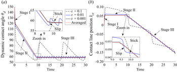
Figure 8 shows the evolutional behaviour of the dynamic contact angle  $\theta _a$ and the contact line position
 $\hat {x}_{ct}$ modelled by (3.2) with different periods
 $\varepsilon =10^{-1}, 10^{-2}$ and
 $10^{-3}$. The dimensionless velocity is
 ${v}=0.01$, and the initial contact angle is
 $\theta _{init}=150^{\circ }$. It shows a clear three-stage process.
Receding dynamics for  $\varepsilon =0.1, 0.01, 0.001$ and
 ${v}=0.01$ given
 $\theta _A=60^{\circ }$ and
 $\theta _B=120^{\circ }$. (a) Dynamical contact angle starting from
 $\theta _{init}=150^{\circ }$. (b) The contact line position starting from
 $\hat {x}_{ct}=0$.

(i) In the first stage, since the initial contact angle is greater than
$\theta _B=120^{\circ }$ and the wall velocity is positive, the averaged dynamics (3.25) predicts that the contact line $\hat {x}_{ct}$ moves to the positive direction and the contact angle $\theta _a$ decreases towards $\theta _B$. This is consistent with the numerical results of the original dynamics (3.2) (shown by red curves), in particular for small $\varepsilon$ as depicted by the solid blue and black curves. Moreover, this stage is very short and thus is transient.(ii) When
$\theta _a$ is around $\theta _B=120^{\circ }$, the second-stage dynamics emerges. The contact line moves very slowly as if it stays almost unchanged, but the contact angle continues to recede. This behaviour is consistent with the prediction by the averaged dynamics (3.24).(iii) As the receding angle achieves some value around
$\theta _A=60^{\circ }$, the dynamical process goes into the third stage. The contact angle oscillates around the effective receding contact angle given by (3.26). There are also oscillations for the contact line position $\hat {x}_{ct}$. However, the averaged position of the contact line increases linearly with respect to the time.


In the third stage, the contact line moves to the negative direction relative to the wall with a stick-slip effect. Take the  $\varepsilon =0.01$ case for example (in the zoom-in plot). As the contact angle achieves approximately
 $57.5^{\circ }$, the contact line starts to move fast (e.g. the zoom-in plot of the
 $\varepsilon =0.01$ curve when
 $t=9.5$). This fast movement of
 $\hat {x}_{ct}$ in turn leads to a fast increase of
 $\theta _a$ until
 $\theta _a$ arrives at approximately
 $62^{\circ }$. This is the slip behaviour of the contact line. When
 $\theta _a$ is around
 $62^{\circ }$, the deviation of
 $\theta _a$ from
 $\varphi (\hat {x}_{ct})$ is small so that the contact line moves very slowly as if it sticks there (e.g.
 $\hat {x}_{ct}\approx 0.047$ in the zoom-in plot of the
 $\varepsilon =0.01$ curve). The angle
 $\theta _a$ decreases slowly towards
 $57.5^{\circ }$ and another stick-slip period follows. Both the oscillation of the contact angle and the stick-slip of the contact line position share the same period proportional to
 $\varepsilon$. The stick-slip motion has also been discussed in detail in Xu & Wang (Reference Xu and Wang2020).
Figure 8 also shows that the dynamics of the contact angle and the contact line position converges to the averaged dynamics (red curves) modelled by (3.24) and (3.25) as the period  $\varepsilon$ decreases. When
 $\varepsilon =10^{-3}$, the differences between the original dynamics and the averaged dynamics is quite small.
When  $v$ is negative, the situation is similar to that shown in figure 8. In this case, one will observe the effective advancing contact angle in the third stage instead (also see the plots in figure 9). For the other choices of
 $\theta _A$,
 $\theta _B$ and initial angle
 $\theta _{init}$, the numerical results are also similar except that the three-stage behaviour may be replaced by a two-stage process or a one-stage process depending on whether
 $\theta _{init}$ is inside or outside
 $[\theta _A,\theta _B]$.
Advancing and receding dynamics for  $\varepsilon =0.01$ and
 ${v}=\pm 0.02,\pm 0.01,\pm 0.005$ given
 $\theta _A=60^{\circ }$ and
 $\theta _B=120^{\circ }$. (a) Dynamical contact angle starting from
 $\theta _{init}=100^{\circ }$. (b) The contact line position starting from
 $0$. From top to bottom, the solid curves represent the contact angle and contact line motion in the original dynamics. The dashed curves are the corresponding averaged dynamics.

Figure 9 shows the effect of velocity  $v$ on the dynamics. In these experiments, we fix
 $\varepsilon =0.01$,
 $\theta _{init}=100^{\circ }$ and vary the dimensionless velocity
 ${v}$ from 0.02 to -0.02. As shown by the bottom three groups of curves in figure 9, when
 ${v}>0$, the contact angle
 $\theta _a$ decreases towards the receding angle and the contact line position
 $\hat {x}_{ct}$ moves to the negative direction. In the stick-slip stage, the effective contact line velocity in the averaged dynamics is exactly equal to the wall velocity
 ${v}$. The effective receding angle also depends on
 ${v}$. As
 $|{v}|$ becomes smaller, the effective receding angle is closer to
 $\theta _A=60^{\circ }$ from below. In the case
 ${v}<0$, the advancing dynamics is observed and
 $\theta _a$ increases until it starts to oscillate around the effect advancing angle. Then,
 $\hat {x}_{ct}$ moves to the positive direction with an averaged velocity equal to
 ${v}$. As
 $|{v}|$ becomes smaller, the effective advancing angle is closer to
 $\theta _B=120^{\circ }$ from above. This validates our analysis in § 3.1. Moreover, the sensitivities of the effective receding and advancing contact angles to
 $|{v}|$ are different and asymmetric in this case.
Finally, we will study the effect of the geometric factor  $g(\theta _a)$. We solve the problem (3.2) for two different choices of
 $g$, which correspond to the moving contact line problems in a microscopic channel (
 $g=4\mathcal {G}_1$) and on a moving fibre (
 $g=4\mathcal {G}_2$). Figure 10 shows the dynamics of the advancing and receding angles. It is clear that the geometric factor affects the dynamic process, especially the first two stages. The contact angle approaches its equilibrium value in the micro-channel case much faster than it does in the moving fibre case. However, the effective advancing and receding angles are the same in the two cases and they only depend on the dynamic factor
 $f(\theta _a)$, as shown by (3.26).
Advancing and receding dynamics for  $\varepsilon =0.01$ and
 ${v}=\pm 0.01$ given
 $\theta _A=60^{\circ }$ and
 $\theta _B=120^{\circ }$. (a) Dynamical contact angle starting from
 $\theta _{init}=100^{\circ }$. (b) The contact line position starting from
 $0$. From top to bottom, the solid curves represent the contact angle and contact line dynamics with respect to
 ${v}=-0.01$ and
 ${v}=0.01$. Black curves show the dynamics in the case of a fibre while blue curves show the dynamics in the case of a microscopic channel. The dashed curves are the corresponding averaged dynamics.

5.2. Comparison with experimental results
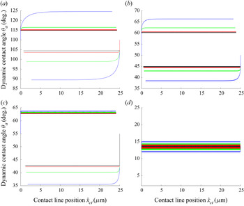
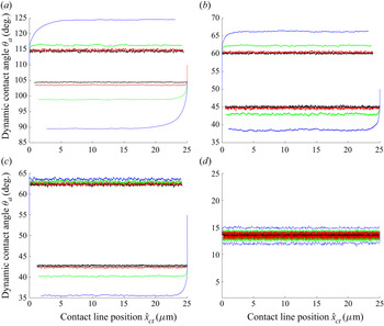
In this subsection, we will use our model and analysis to explain the experimental results of Guan et al. (Reference Guan, Wang, Charlaix and Tong2016a,Reference Guan, Wang, Charlaix and Tongb). There, the dynamic CAH is observed by careful design of physical experiments. A very thin glass fibre with an inhomogeneous surface is inserted into a liquid reservoir. The fibre moves up and down so that a contact line moves on its surface. The capillary forces on the fibre are measured by atomic force microscopy (AFM) and the effective contact angles are computed. Several liquids with different surface tensions, viscosities and equilibrium angles are tested in their experiments. Many interesting phenomena are observed in the experiments. It is found that the dependence of the advancing and receding contact angles on the fibre velocity is not unified (see figure 6 in Guan et al. Reference Guan, Wang, Charlaix and Tong2016b). In some cases (e.g. the water–air system), the dependence of the advancing and receding contact angles on the velocity is very asymmetric. In some cases (e.g. the octanol–air system), this dependence seems symmetric. In some other cases (e.g. the FC77–air system), the advancing and receding contact angles are all very small and close to each other.
To compare with the experiments, we use the reduced model (2.24) which is an approximation for the problem in Guan et al. (Reference Guan, Wang, Charlaix and Tong2016b). The radius of the fibre is  $r_0=1.1\,\mathrm {\mu } \textrm {m}$ which is consistent with the experiment. We suppose the surface of the fibre is composed of two different materials
 $A$ and
 $B$ with different Young's angles
 $\theta _A$ and
 $\theta _B$. On the surface, the pattern of the Young's angle
 $\varphi (z)$ is a piecewise constant periodic function with
 $\varphi _{\chi }(z)=\theta _A$ if
 $0\leqslant z<\chi$ and
 $\varphi _{\chi }(z)=\theta _B$ if
 $\chi \leqslant z<1$, where
 $\chi$ is the percentage of material
 $A$ in a period. For the convenience in numerical computations, we smooth this discontinuous pattern by a hyperbolic tangent function
 \begin{equation} \varphi_{\chi}^{\delta}(z)=\dfrac{\theta_A+\theta_B}{2}+\dfrac{\theta_B-\theta_A}{2}\tanh\left(\dfrac{\sin(2{\rm \pi} z)-\sin(\chi-1/2){\rm \pi}}{\delta}\right), \end{equation}
where  $\delta \ll 1$ is chosen to control the thickness of the smooth transition between two patterns. We use
 $\varphi _{\chi }^{\delta }$ in our simulations. Here,
 $\theta _A$ and
 $\theta _B$ can be chosen approximately according to the receding and advancing contact angles in the experiments with the smallest moving speed. We choose the fraction
 $\chi$ and the dimensionless friction coefficient
 $\alpha$ as fitting parameters. The dimensionless wall velocity is represented by
 $v={\mu u_{wall}}/{\gamma }$, where the fibre speed
 $|u_{wall}|$ is suggested by the experiments as
 $2\,\mathrm {\mu } \textrm {m}\,\textrm {s}^{-1}, 5\,\mathrm {\mu } \textrm {m}\,\textrm {s}^{-1}, 20\,\mathrm {\mu } \textrm {m}\,\textrm {s}^{-1}$ and
 $50\,\mathrm {\mu } \textrm {m}\,\textrm {s}^{-1}$. We refer to table 1 of Guan et al. (Reference Guan, Wang, Charlaix and Tong2016b) for the material properties, especially the surface tension
 $\gamma$ and the viscosity
 $\mu$. Since the capillary lengths of the materials under consideration have the range 0.86–2.71 mm, we choose it to be
 $l_c=1$mm. The logarithm of the cutoff parameter is fixed at
 $\ln \zeta =10$. As we observe in the numerical experiments, the variation of
 $\ln \zeta$ in its reasonable regime (of order
 $O(10)$) does not affect the results too much.
The numerical results are given in figure 11. We could see that the dependence of the CAH on the capillary number is not unified. For all the four cases, the advancing and receding contact angles and their dependence on the wall velocity are similar to those in the experiments in Guan et al. (Reference Guan, Wang, Charlaix and Tong2016a,Reference Guan, Wang, Charlaix and Tongb). The numerical results also agree with the discussions in § 4.1 based on the formula (3.26) of the effective contact angle. This also indicates that the experimental observations may be understood from our theoretical analysis in § 3, especially (3.26) on the effective contact angles. There we show that effective advancing and receding contact angles depend on the capillary number, the friction coefficient, the Young's angles of the inhomogeneous substrate and also the spatial distributions of the patterns. All these parameters have important impacts and the interplay among them gives rise to very complicated experimental phenomena.
Dependence of CAH on different wall speeds. The dimensional period of the chemical pattern is set to be  $\varepsilon =0.05\,\mathrm {\mu }$m. (a) Water–air,
 $\theta _A=105^{\circ }$,
 $\theta _B=115^{\circ }$,
 $\alpha =4\times 10^{5}$ and
 $\chi =0.9$. (b) Octanol–air,
 $\theta _A=45^{\circ }$,
 $\theta _B=60^{\circ }$,
 $\alpha =1\times 10^{4}$ and
 $\chi =0.4$. (c) Decane–air,
 $\theta _A=43^{\circ }$,
 $\theta _B=63^{\circ }$,
 $\alpha =5\times 10^{4}$ and
 $\chi =0.9$. (d) FC77–air,
 $\theta _A=13^{\circ }$,
 $\theta _B=14^{\circ }$,
 $\alpha =1\times 10^{3}$ and
 $\chi =0.4$. The black, red, green and blue curves represent the results with fibre speeds of
 $|u_{wall}|=2\,\mathrm {\mu }$m,
 $5\,\mathrm {\mu }$m,
 $20\,\mathrm {\mu }$m and
 $50\,\mathrm {\mu }$m, respectively.

In real experiments, there are always thermal noises which affect the dynamics of the contact line. To make the numerical results more comparable to the experiments, we add a stochastic force in (2.7) to model other non-deterministic effects, e.g. thermal noises. The resulting stochastic system for the apparent contact angle  $\theta _d$ and contact line position
 $\hat {x}_{ct}$ reads
 \begin{equation} \left. \begin{aligned} \dot{\theta}_a & =g(\theta_a)(f(\theta_a)(\cos\hat{\theta}_Y(\hat{x}_{ct})-\cos\theta_a+\sigma\dot{W})+v),\\ \dot{\hat{x}}_{ct} & = f(\theta_a)(\cos\hat{\theta}_Y(\hat{x}_{ct})-\cos\theta_a+\sigma\dot{W}). \end{aligned} \right\} \end{equation}
This system of equations should be understood in the Itô sense. Since the contact angle and the contact line position are linked by the kinematic constraint (e.g. (2.12) and (2.21)) through the geometric factor  $g(\theta _a)$, they are driven by the same Brownian motion
 $W(t)$. We choose the noise level to be small so that it does not affect the dynamics too much. We then numerically solve (5.2) for one sample path using the Euler–Maruyama scheme. Numerical results by solving the stochastic equation (5.2) are shown in figure 12. We could see a similar velocity dependence of the CAH as that in figure 11 in the deterministic case. Moreover, the dynamic behaviours fit well with the experiments for all the four cases, i.e. the water–air, octanol–air, decane–air and FC77–air systems (Guan et al. Reference Guan, Wang, Charlaix and Tong2016b).
Dependence of CAH on different wall speeds in the presence of noise. The dimensional period of the chemical pattern is set to  $\varepsilon =0.05\,\mathrm {\mu }$m. The noise level
 $\sigma$ is chosen case by case without affecting the effective advancing and receding angles. (a) Water–air,
 $\theta _A=105^{\circ }$,
 $\theta _B=115^{\circ }$,
 $\alpha =4\times 10^{5}$,
 $\chi =0.9$ and
 $\sigma =0.1$. (b) Octanol–air,
 $\theta _A=45^{\circ }$,
 $\theta _B=60^{\circ }$,
 $\alpha =1\times 10^{4}$,
 $\chi =0.4$ and
 $\sigma =0.02$. (c) Decane–air,
 $\theta _A=43^{\circ }$,
 $\theta _B=63^{\circ }$,
 $\alpha =5\times 10^{4}$,
 $\chi =0.9$ and
 $\sigma =0.03$. (d) FC77–air,
 $\theta _A=13^{\circ }$,
 $\theta _B=14^{\circ }$,
 $\alpha =1\times 10^{3}$,
 $\chi =0.4$ and
 $\sigma =0.002$. The black, red, green and blue curves represent the results with fibre speeds at
 $|u_{wall}|=2\,\mathrm {\mu }$m,
 $5\,\mathrm {\mu }$m,
 $20\,\mathrm {\mu }$m and
 $50\,\mathrm {\mu }$m, respectively.

In the end, we would like to remark that the previous comparisons with experiments are almost quantitative, since the fibre velocities are chosen to be the same as in the experiments. Here, we choose the fraction  $\chi$ of the chemical pattern as a fitting parameter. The reason can be understood as follows. In our simplified model, we assume that the contact line on the fibre is circular and the liquid–air interface is axisymmetric. This assumption does not hold in real experiments, where the chemical inhomogeneity is very complex on the fibre surface. The relaxation behaviour of the contact line is much more complicated than that in our model. Although it is possible to use a circular curve to approximate the contact line on such surfaces by homogenization (Joanny & De Gennes Reference Joanny and De Gennes1984; Xu Reference Xu2016), the effective pattern in the axial direction might be different for different liquids even on the same substrate. This is due to the fact that the correlation length of the oscillating contact line can be very different (Golestanian & Raphaël Reference Golestanian and Raphaël2003; Golestanian Reference Golestanian2004). Actually, this can be seen from the experiments in Guan et al. (Reference Guan, Wang, Charlaix and Tong2016b), where the periods of the effective patterns seem very different for different fluids. The characterization of dynamic CAH on general surfaces with chemical and geometrical roughness in three dimensions is very interesting and will be left for future work.
6. Conclusion
In this paper, we derive a formula (4.1) for the apparent contact angles on chemically inhomogeneous surfaces. It can be regarded as a Cox-type boundary condition for the time averaged apparent contact angle on these surfaces. The formula characterizes quantitatively how the averaged advancing and receding contact angles depend on the velocity, the Young's angles and the distributions of the chemical inhomogeneities. It can be used to understand the complicated behaviours for the dynamic CAH observed in experiments.
The derivation of the above formula is based on a reduced model for the macroscopic contact angle for moving contact line problems. Without considering the contact line friction, the model is a leading-order approximation for the famous Cox's formula for small capillary number and is easier to analyse in cases with inhomogeneous surfaces. The reduced model is derived by using the Onsager principle as an approximation tool, which is much simpler than the standard asymptotic matching methods used in Cox (Reference Cox1986).
Although the main result is obtained by averaging the reduced model for a liquid–vapour system with small size, it can be generalized to other two-phase flow systems using the same averaging technique. In particular, it is straightforward to do averaging for the Cox's boundary condition and derive a similar formula (4.8). These formulae can be used coupled with the standard two-phase Navier–Stokes equation. This will lead to a coarse-graining model for two-phase flow systems on chemically inhomogeneous surfaces. The dynamic CAH is given by these formulae and one does not need to resolve the microscopic inhomogeneity of the solid surfaces as in Yue (Reference Yue2020).
We mainly focus on the two-dimensional problem in the paper. But the results are useful for three-dimensional problems when the inhomogeneity is simple. For example, when the defect is dilute, the static advancing and receding contact angles have been derived by Joanny & De Gennes (Reference Joanny and De Gennes1984). Then it is possible to reduce the three-dimensional problem to a two-dimensional one by symmetry assumptions. Thus, one can apply the results in this paper to these problems. Some other problems may be handled in a similar way by combing our analysis with the modified Cassie–Baxter equation for static CAH in Choi et al. (Reference Choi, Tuteja, Mabry, Cohen and McKinley2009), Xu & Wang (Reference Xu and Wang2013) and Xu (Reference Xu2016).
For more general three-dimensional problems with rough or chemically inhomogeneous surfaces, the relaxation dynamics of the contact line is very complicated. The CAH may also depend on the depinning processes of a contact line even in quasi-static processes (Choi et al. Reference Choi, Tuteja, Mabry, Cohen and McKinley2009; Iliev et al. Reference Iliev, Pesheva and Iliev2018). For dynamical problems, the correlations and roughening processes of the contact line make the problem even more complicated (Golestanian & Raphaël Reference Golestanian and Raphaël2003; Golestanian Reference Golestanian2004). Both the time averaging and the spatial homogenization need to be considered simultaneously. The analysis for these problems will be left for future work.
Finally, we would like to remark that we mainly discussed Cox-type boundary conditions in this paper. However, these conditions might fail to predict the experimental observations when the flow field is very complex near the contact line (Blake, Bracke & Shikhmurzaev Reference Blake, Bracke and Shikhmurzaev1999; Clarke & Stattersfield Reference Clarke and Stattersfield2006; Davis & Davis Reference Davis and Davis2013; Mohammad Karim, Davis & Kavehpour Reference Mohammad Karim, Davis and Kavehpour2016). This fact has been highlighted in a recent work (Shikhmurzaev Reference Shikhmurzaev2020). There, the author presents some examples as a ‘litmus test’ for the mathematical models for moving contact lines and concludes that the standard models like the Cox's boundary condition cannot explain the contact line motion in all situations. The apparent contact angle cannot be described by a single function of the contact line velocity in those examples. A model that might pass the test is the interface formation model (Shikhmurzaev Reference Shikhmurzaev1993, Reference Shikhmurzaev2007). In this model, wetting of a substrate is induced by formation of a new liquid–solid interface and the process is described by some complicated partial differential equations. The contact angle is still given by Young's equation while the surface tensions are not constants. Although there are some controversies on this model (Eggers & Evans Reference Eggers and Evans2004; Shikhmurzaev & Blake Reference Shikhmurzaev and Blake2004; Lindner-Silwester & Schneider Reference Lindner-Silwester and Schneider2005; Shikhmurzaev Reference Shikhmurzaev2006), its equivalence to the standard slip model has been recently shown in certain parameter regimes (Sibley, Savva & Kalliadasis Reference Sibley, Savva and Kalliadasis2012; Sibley et al. Reference Sibley, Nold, Savva and Kalliadasis2015b). It would be very interesting to study the homogenization of the interface formation model on inhomogeneous or rough substrates (see discussions in e.g. Shikhmurzaev Reference Shikhmurzaev2020). This is outside of the scope of this paper.
Funding
The work of Z.Z. was partially supported by the NSFC grant (No. 11731006, No. 12071207), the Guangdong Provincial Key Laboratory of Computational Science and Material Design (No. 2019B030301001) and the Guangdong Basic and Applied Basic Research Foundation (2021A1515010359). The work of X.X. partially supported by the NSFC grant (No. 11971469) and by the National Key R&D Program of China under Grant 2018YFB0704304 and Grant 2018YFB0704300.
Declaration of interests
The authors report no conflict of interest.
Appendix A. Derivation for a continuum model for moving contact lines by the Onsager principle
Consider a region  $\varOmega$ near the contact line as in figure 13. For simplicity, we suppose
 $\varOmega$ is a two-dimensional domain. The boundary of
 $\varOmega$ is composed of two parts, the lower solid boundary
 $\varGamma _S$ and the outer boundary
 $\varGamma _{O}$. On
 $\varGamma _S$, there exists a moving contact line, which is an intersection point between the solid boundary and the two-phase flow interface
 $\varGamma$. Then
 $\varOmega$ represents an open system near the contact point. In the following, we will derive a sharp interface continuum model for moving contact lines. We adopt the Onsager principle to derive the model. The method has been used to develop the generalized Navier slip boundary condition for a diffuse interface model in Qian, Wang & Sheng (Reference Qian, Wang and Sheng2006). In the derivation, we ignore the gravitational force and the inertial effect, which can be added simply if needed.
A domain of two-phase flow with a moving contact line.

To use the Onsager principle, we first compute the rate of change of the total energy in the system. The total free energy consists of three interface energies
 \begin{equation} \mathcal{E}=\int_{\varGamma_{SA}}\gamma_{SA} \,{\rm d}s + \int_{\varGamma_{SB}}\gamma_{SB} \,{\rm d}s +\int_{\varGamma}\gamma \,{\rm d}s, \end{equation}
where  $\varGamma _{SA}$ and
 $\varGamma _{SB}$ are respectively the parts of solid boundary in contact with the fluid
 $A$ and fluid
 $B$,
 $\gamma _{SA}$ and
 $\gamma _{SB}$ are corresponding surface tensions and
 $\gamma$ is the surface tension of the two-phase flow interface. Direct calculations give
 \begin{equation} \dot{\mathcal{E}}=\gamma(\cos\theta_d-\cos\theta_Y) v_{ct} +\gamma \int_{\varGamma}v_n\kappa \,{\rm d}s. \end{equation}
Here,  $\theta _d$ is the dynamic contact angle with respect to the fluid
 $A$,
 $\theta _Y$ is Young's angle,
 $v_{ct}$ is the velocity of the contact line,
 $v_n=\boldsymbol {v}\boldsymbol {\cdot }\boldsymbol {n}$ is the normal velocity and
 $\kappa$ is the curvature of the interface. In the derivation, we have also used Young's equation
 $\gamma \cos \theta _Y=\gamma _{SB}-\gamma _{SA}$.
The energy dissipation function, which is defined as half of the total energy dissipation rate in the system, can be written as
 \begin{align} \varPhi&= {\int_{\varOmega_A}\dfrac{\mu_A}{4} |\boldsymbol{\nabla} \boldsymbol{v}+\boldsymbol{\nabla} \boldsymbol{v}^{T}|^{2} \,{{\rm d}\kern0.06em x} +\int_{\varOmega_B}\dfrac{\mu_B}{4} |\boldsymbol{\nabla} \boldsymbol{v}+\boldsymbol{\nabla} \boldsymbol{v}^{T}|^{2} \,{{\rm d}\kern0.06em x}} + \int_{\varGamma_{SA}}\dfrac{\beta_A}{2} v_{\tau}^{2} \,{{\rm d}\kern0.06em x} \nonumber\\ &\quad +\int_{\varGamma_{SB}}\dfrac{\beta_B}{2} v_{\tau}^{2} \,{{\rm d}\kern0.06em x} +\dfrac{\xi}{2} v_{ct}^{2}, \end{align}
where  $\varOmega _A$ and
 $\varOmega _B$ are the regions in
 $\varOmega$ occupied by fluid A and fluid B, respectively,
 $\boldsymbol {v}$ is the corresponding velocity field,
 $v_{\tau }$ is the slip velocity on the solid boundary,
 $\mu _A$ and
 $\mu _B$ are viscosity parameters,
 $\beta _A$ and
 $\beta _B$ are phenomenological slip coefficients and
 $\xi$ is the friction coefficient of the contact line. The normal velocity on the solid boundary
 $\varGamma _{S}$ is zero.
Since the system is an open system, we need also to consider the work to the outer fluids at the boundary  $\varGamma _O$. It is given by
 \begin{equation} \dot{\mathcal{E}}^{*}={-}\int_{\varGamma_O}\ \boldsymbol{F}_{ext}\boldsymbol{\cdot}\boldsymbol{v}\,{\rm d}s={-}\int_{\varGamma_{OA}}\boldsymbol{F}_{ext}\boldsymbol{\cdot}\boldsymbol{v}_A\,{\rm d}s-\int_{\varGamma_{OB}}\boldsymbol{F}_{ext}\boldsymbol{\cdot}\boldsymbol{v}_B\,{\rm d}s, \end{equation}
where  $\varGamma _{OA}$ and
 $\varGamma _{OB}$ are the respective open boundaries in contact with fluid A and fluid B.
With the above definitions, the Onsager principle states that (Doi Reference Doi2013) the dynamical equation of the system is given by minimizing the Onsager–Machlup action defined as follows:
 \begin{equation} {O}=\dot{\mathcal{E}}+\dot{\mathcal{E}}^{*}+\varPhi, \end{equation}
under the constraint of incompressibility condition
 \begin{equation} \boldsymbol{\nabla}\boldsymbol{\cdot} \boldsymbol{v}=0. \end{equation}
Introduce a Lagrangian multiplier  $p(x)$ in
 $\varOmega$. We minimize the following modified functional with respect to the velocity:
 \begin{equation} \mathcal{R}_{\lambda}=\dot{\mathcal{E}}+\dot{\mathcal{E}}^{*}+\varPhi-\int_{\varOmega_A\cup\varOmega_B} p \boldsymbol{\nabla} \boldsymbol{\cdot} \boldsymbol{v} \,{{\rm d}\kern0.06em x}. \end{equation}
Direct calculation for the first variation of  $\mathcal {R}_{\lambda }$ gives
 \begin{align} &\delta \mathcal{R}_{\lambda}=\int_{\varGamma}\gamma\kappa \delta v_n \,{\rm d}s +\gamma(\cos\theta_a-\cos\theta_Y) \delta v_{ct} -\int_{\varGamma_O} \boldsymbol{F}_{ext}\boldsymbol{\cdot}\delta \boldsymbol{v} \,{\rm d}s \nonumber\\ &\quad {+\int_{\varOmega_A} \dfrac{\mu_A}{2}(\boldsymbol{\nabla} \boldsymbol{v}+\boldsymbol{\nabla} \boldsymbol{v}^{\rm T}) : (\boldsymbol{\nabla} \delta \boldsymbol{v}+\boldsymbol{\nabla} \delta \boldsymbol{v}^{\rm T}) \,{{\rm d}\kern0.06em x} +\int_{\varOmega_B} \dfrac{\mu_B}{2}(\boldsymbol{\nabla} \boldsymbol{v}+\boldsymbol{\nabla} \boldsymbol{v}^{\rm T}) : (\boldsymbol{\nabla} \delta \boldsymbol{v}+\boldsymbol{\nabla} \delta \boldsymbol{v}^{\rm T}) \,{{\rm d}\kern0.06em x}}\nonumber\\ &\quad +\int_{\varGamma_{SA}}\beta_A v_{\tau}\delta v_{\tau} \,{\rm d}s +\int_{\varGamma_{SB}}\beta_B v_{\tau}\delta v_{\tau} \,{\rm d}s+ \xi v_{ct}\delta v_{ct} -\int_{\varOmega_A\cup\varOmega_B} p \boldsymbol{\nabla} \boldsymbol{\cdot} \delta \boldsymbol{v} \,{{\rm d}\kern0.06em x}. \end{align}
Integration by parts gives
 \begin{align} &{\int_{\varOmega_A} \dfrac{\mu_A}{2}(\boldsymbol{\nabla} \boldsymbol{v}+\boldsymbol{\nabla} \boldsymbol{v}^{\rm T}) : (\boldsymbol{\nabla} \delta \boldsymbol{v}+\boldsymbol{\nabla} \delta \boldsymbol{v}^{\rm T}) \,{{\rm d}\kern0.06em x}}\nonumber\\ &\quad {= \int_{\partial \varOmega_A} \mu_A (\boldsymbol{\nabla} \boldsymbol{v}+\boldsymbol{\nabla} \boldsymbol{v}^{\rm T}) \boldsymbol{n} \boldsymbol{\cdot} \delta \boldsymbol{v} \,{{\rm d}\kern0.06em x}-\int_{\varOmega_A}\boldsymbol{\nabla} \boldsymbol{\cdot}(\mu_A(\boldsymbol{\nabla} \boldsymbol{v}+\boldsymbol{\nabla} \boldsymbol{v}^{\rm T} ))\boldsymbol{\cdot} \delta \boldsymbol{v} \,{{\rm d}\kern0.06em x}}, \end{align}
and
 \begin{equation} -\int_{\varOmega_A} p \boldsymbol{\nabla} \boldsymbol{\cdot} \delta \boldsymbol{v}\, {{\rm d}\kern0.06em x}={-}\int_{\partial \varOmega_A} p \boldsymbol{n} \boldsymbol{\cdot} \delta \boldsymbol{v} \,{{\rm d}\kern0.06em x}+\int_{\varOmega_A} \boldsymbol{\nabla} p \boldsymbol{\cdot} \delta \boldsymbol{v} \,{{\rm d}\kern0.06em x}. \end{equation}
Similar calculations can be done in  $\varOmega _B$. Combing all these calculations, we immediately derive the corresponding Euler–Lagrange equation for (A7)
 \begin{equation} \left.
\begin{array}{l@{}} -{\boldsymbol{\nabla}
\boldsymbol{\cdot}(\mu(\boldsymbol{\nabla}
\boldsymbol{v}+\boldsymbol{\nabla} \boldsymbol{v}^{\rm T}
))} +\boldsymbol{\nabla} p=0\\ \boldsymbol{\nabla}
\boldsymbol{\cdot}\boldsymbol{v}=0 \end{array}
\right\} \quad \text{in } \varOmega,
\end{equation}
coupled with the interface condition on  $\varGamma$
 \begin{equation} [\boldsymbol{v}]=0,\quad {\left[\mu (\boldsymbol{\nabla} \boldsymbol{v}+\boldsymbol{\nabla} \boldsymbol{v}^{\rm T})-p \boldsymbol{I}\right] \boldsymbol{n} =\gamma\kappa \boldsymbol{n}} \quad \text{on } \varGamma, \end{equation}
the Navier slip boundary condition on  $\varGamma _S$
 \begin{equation} v_n=0,\quad \beta(x) v_{\tau}={-}\mu \dfrac{\partial v_{\tau} }{\partial n} \quad \text{on } \varGamma_S \end{equation}
and the condition for the moving contact line
 \begin{equation} \xi v_{ct}={-}\gamma(\cos\theta_d-\cos\theta_Y). \end{equation}
Here
 \begin{equation} \mu(x)= \left\{
\begin{array}{@{}ll} \mu_A, & \text{if } x\in\varOmega_A;\\
\mu_B, & \text{if } x\in\varOmega_B; \end{array}\right.
\quad \text{and} \quad \beta(x)=\left\{\begin{array}{@{}ll}
\beta_A, & \text{if } x\in\varGamma_{SA};\\ \beta_B, &
\text{if } x\in\varGamma_{SB}. \end{array}\right.
\end{equation}
On the outer boundary  $\varGamma _O$, we also have a relation for the external force such that
 \begin{equation} \boldsymbol{F}_{ext}={\left(\mu (\boldsymbol{\nabla} \boldsymbol{v}+\boldsymbol{\nabla} \boldsymbol{v}^{\rm T})-p \boldsymbol{I}\right) \boldsymbol{n}}. \end{equation}
The boundary condition (A14) for moving contact lines is exactly the model derived in Ren & E (Reference Ren and E2007). Specifically, when  $\xi =0$, the condition is reduced to
 \begin{equation} \theta_d=\theta_Y. \end{equation}
This implies that the microscopic dynamic contact angle is equal to the Young's angle. Together with the Navier slip boundary condition (A13), this is the model used in the asymptotic analysis in Cox (Reference Cox1986).
Therefore, the above analysis indicates that some well-known continuum models for moving contact lines can be derived in a variational framework of the Onsager principle.
Appendix B. Calculate the energy dissipation in a wedge region
Since we assume the region is in steady state,  $\varPhi _{vis}$ can be computed by solving the Stokes equation in the region. For simplicity, we can change variables and consider the problem as shown in figure 14. We choose a polar coordinate system
 $(r,\phi )$ near the contact point. Let the contact point locate at the origin
 $O$. The polar axis is in the right direction. In this system, the solid boundary will have a velocity
 $U=-v_{ct}$, as shown in figure 14. The viscous energy dissipation in the wedge region can be computed by solving the Stokes equations
 \begin{equation} \left.\begin{array}{l@{}} -\mu_A\Delta v_A+\boldsymbol{\nabla} p_A=0, \\ \text{div} v_A=0, \end{array} \right\}\quad \text{in Region A;} \end{equation}
and
 \begin{equation} \left.\begin{array}{l@{}} -\mu_B\Delta v_B+\boldsymbol{\nabla} p_B=0, \\ \text{div} v_B=0, \end{array} \right\}\quad \text{in Region B.} \end{equation}
We use no slip boundary condition on  $\varGamma _S$. The two-phase flow interface is assumed unchanged with time. Then the Stokes equation can be solved by the biharmonic equation.
The wedge region near the moving contact point.

We now calculate the dissipation in the wedge. To solve the problem, we apply the computations in Cox (Reference Cox1986). Introduce two streamfunctions  $\psi _A$ and
 $\psi _B$. We have
 \begin{equation} (v_A)_r=\dfrac{1}{r}\dfrac{\partial\psi_A}{\partial\phi}, \quad (v_A)_{\phi}={-}\dfrac{\partial \psi_A}{\partial r}. \end{equation}
Here,  $(v_A)_r$ is the velocity in the radial direction, and
 $(v_A)_{\phi }$ is the velocity in the angular direction. Similar formulae hold for
 $v_B$. Then we have
 \begin{equation} \Delta^{2}\psi_A=0,\quad \Delta^{2}\psi_B=0. \end{equation}
The equations should satisfy the boundary conditions on the solid surface. We choose the no-slip boundary condition for the velocity except in the vicinity of the contact line when  $r< l$ with the microscopic length
 $l$ is a cutoff parameter. When
 $r>l$, we have
 $$\begin{gather} \psi_A=0,\quad \dfrac{\partial\psi_A}{\partial \phi}=Ur,\quad \text{on } \phi=0; \end{gather}$$
 $$\begin{gather}\psi_B=0,\quad \dfrac{\partial\psi_B}{\partial \phi}={-}Ur,\quad \text{on } \phi={\rm \pi}. \end{gather}$$
On the interface  $\phi =\theta _a$, we have
 \begin{equation} \left. \begin{aligned} & \dfrac{\partial\psi_A}{\partial r}=\dfrac{\partial\phi_B}{\partial r}=0, \\ & \dfrac{\partial \psi_A}{\partial\phi}=\dfrac{\partial \psi_B}{\partial\phi},\\ & \dfrac{1}{r^{2}}\dfrac{\partial^{2}\psi_A}{\partial\phi^{2}}-\dfrac{\partial^{2}\psi_A}{\partial r^{2}}+\dfrac{1}{r}\dfrac{\partial\psi_A}{\partial r} =\lambda \left(\dfrac{1}{r^{2}}\dfrac{\partial^{2}\psi_B}{\partial\phi^{2}}-\dfrac{\partial^{2}\psi_B}{\partial r^{2}}+\dfrac{1}{r}\dfrac{\partial\psi_B}{\partial r}\right), \end{aligned} \right\} \end{equation}
where  $\lambda ={\mu _A}/{\mu _B}$.
The biharmonic equations in the wedge domains can be solved combining the above boundary and interface conditions. This leads to
 $$\begin{gather} \psi_A=U r\left( (C_A\phi+D_A)\cos\phi+(E_A\phi+F_A)\sin\phi \right); \end{gather}$$
 $$\begin{gather}\psi_B=U r\left( (C_B\phi+D_B)\cos\phi+(E_B\phi+F_B)\sin\phi \right). \end{gather}$$
Here, the two groups of coefficients are given by
 \begin{align} C_A&=\sin\theta_a\left(-\lambda({\rm \pi}\sin\theta_a+\sin^{2}\theta_a\cos\theta_a+\theta_a({\rm \pi}-\theta_a)\cos\theta_a) \right.\nonumber\\ &\left.\quad +\cos\theta_a(\sin^{2}\theta_a-({\rm \pi}-\theta_a)^{2})\right)/\delta; \end{align}
 \begin{align} D_A&=0; \end{align}
 \begin{align} E_A&=\sin^{2}\theta_a\left(-\lambda(\sin^{2}\theta_a+\theta_a({\rm \pi}-\theta_a))+\sin^{2}\theta_a-({\rm \pi}-\theta_a)^{2}\right)/\delta; \end{align}
 \begin{align} F_A&=\theta_a\left(\lambda(\sin^{2}\theta_a+\theta_a({\rm \pi}-\theta_a)+{\rm \pi}\sin\theta_a\cos\theta_a)+(-\sin^{2}\theta_a+({\rm \pi}-\theta_a)^{2})\right)/\delta; \end{align}
and
 \begin{align} C_B&=\dfrac{-D_B}{\rm \pi}=\sin\theta_a\left(\lambda\cos\theta_a(\theta_a^{2}-\sin^{2}\theta_a)-{\rm \pi}\sin\theta_a+\sin^{2}\theta_a\cos\theta_a\right.\nonumber\\ &\left.\quad +\theta_a({\rm \pi}-\theta_a)\cos\theta_a \right)/\delta; \end{align}
 \begin{align} E_B&=\sin^{2}\theta_a\left(\lambda(\theta_a^{2}-\sin^{2}\theta_a)+(\sin^{2}\theta_a+\theta_a({\rm \pi}-\theta_a))\right)/\delta;\\ F_B&= \left(\lambda(\sin^{2}\theta_a-\theta_a^{2})(\theta_a-{\rm \pi}\cos^{2}\theta_a) -{\rm \pi}({\rm \pi}-\theta_a)\sin\theta_a\cos\theta_a -\theta_a\sin^{2}\theta_a\right.\nonumber\\ \end{align}
 \begin{align} &\left.\quad+{\rm \pi}\sin^{2}\theta_a\cos^{2}\theta_a+{\rm \pi}({\rm \pi}-\theta_a)\theta_a\cos^{2}\theta_a -({\rm \pi}-\theta_a)\theta_a^{2}\right)/\delta. \end{align}
Here
 \begin{equation} \delta=\lambda(\theta_a^{2}-\sin^{2}\theta_a)({\rm \pi}-\theta_a+\sin\theta_a\cos\theta_a)+\left(({\rm \pi}-\theta_a)^{2}-\sin^{2}\theta_a\right)(\theta_a-\sin\theta_a\cos\theta_a). \end{equation}
With the formula for  $\psi _A$ and
 $\psi _B$, we can compute the velocities in the two regions. For liquid A, we have
 $$\begin{gather} (v_A)_r=U\left((C_A+F_A)\cos\phi+(E_A-D_A)\sin\phi-C_A\phi\sin\phi+E_A\phi\cos\phi\right), \end{gather}$$
 $$\begin{gather}(v_A)_\phi={-}U\left( (C_A\phi+D_A)\cos\phi+(E_A\phi+F_A)\sin\phi\right). \end{gather}$$
Then we have
 \begin{equation} v_A=(v_A)_r \boldsymbol{r}+(v_A)_\phi \boldsymbol{\tau}, \end{equation}
where  $\boldsymbol {r}$ and
 $\boldsymbol {\tau }$ are the unit vectors in the radial and angular directions, respectively. We have similar representations for
 $v_B$. The gradient of the velocity gives
 \begin{equation} \boldsymbol{\nabla} v_A=\dfrac{2U}{r}({-}C_A\sin\phi+E_A\cos\phi) \boldsymbol{\tau}\otimes\boldsymbol{r}. \end{equation}
Similarly,
 \begin{equation} \boldsymbol{\nabla} v_B=\dfrac{2U}{r}({-}C_B\sin\phi+E_B\cos\phi) \boldsymbol{\tau}\otimes\boldsymbol{r}. \end{equation}
Then the viscous energy dissipations in the wedge regions can be computed by
 \begin{align} \varPsi&=\int_{l_s}^{R}\int_0^{\theta_a} \dfrac{\mu_A}2|\boldsymbol{\nabla} v_A + (\boldsymbol{\nabla} v_A)^{\rm T}|^{2} r \,{\rm d}\phi \,{\rm d} r+\int_{l_s}^{R}\int_{\theta_a}^{\rm \pi} \dfrac{\mu_B}2|\boldsymbol{\nabla} v_B+(\boldsymbol{\nabla} v_B)^{\rm T}|^{2} r \,{\rm d}\phi \,{\rm d} r\nonumber\\ &=2\mu_A|\ln\zeta|U^{2}\left( C_A^{2}(\theta_a-\sin\theta_a\cos\theta_a)+C_AE_A(\cos 2\theta_a-1)+ E_A^{2}(\theta_a+\sin\theta_a\cos\theta_a)\right.\nonumber\\ &\left.\quad+\lambda\left(C_B^{2}(\theta_a-\sin\theta_a\cos\theta_a)+C_BE_B(\cos 2\theta_a-1)+ E_B^{2}(\theta_a+\sin\theta_a\cos\theta_a) \right) \right). \end{align}
Here,  ${\zeta }=D/l$ is the cutoff parameter with
 $D$ being the characteristic size of the mesoscopic region and
 $l$ being the microscopic size. Direct calculations lead to
 \begin{align} \varPsi&=2\mu_A |\ln\zeta|U^{2} \nonumber\\ &\quad\times \dfrac{\sin^{2}\theta_a\left(\lambda^{2}(\theta_a^{2}-\sin^{2}\theta_a) +2\lambda(\sin^{2}\theta_a+\theta_a({\rm \pi}-\theta_a))+(({\rm \pi}-\theta_a)^{2}-\sin^{2}\theta_a)\right) } {\lambda(\theta_a^{2}-\sin^{2}\theta_a)({\rm \pi}-\theta_a+\sin\theta_a\cos\theta_a)+(({\rm \pi}-\theta_a)^{2}-\sin^{2}\theta_a)(\theta_a-\sin\theta_a\cos\theta_a)}. \end{align}
Appendix C. Properties of the averaged dynamics
In this section, we study the properties of the averaged dynamics (3.24) and (3.25). Without loss of generality, we assume  $v>0$. We also recall that
 $f$ is a non-negative function satisfying
 $f(0)=0$ and
 $f'(\theta )>0$ for
 $\theta \in [0,{\rm \pi} ]$,
 $g$ is a negative function bounded by
 $-M$ and
 $-m$. We consider the behaviour of the dynamic system for different regimes of
 $\varTheta _a$ starting at
 $\varTheta _a(0)>\theta _B$:
(i) When
$\varTheta _a>\theta _B=\max _{0\leqslant y\leqslant 1}\varphi (y)$, the averaged dynamics (3.25) is a good approximation. It yields the following properties:
(a)
$\varTheta _a$ monotonically decreases at a speed of at least $mv$ until it arrives at $\theta _B$.This is because the harmonic average
(C 1)is positive when\begin{equation} C(\varTheta_a)=\left(\int_0^{1}\dfrac{\mathrm{d}z}{\cos\varphi(z)-\cos\varTheta_a}\right)^{{-}1} \end{equation}$\varTheta _a>\theta _B$. As a result, we have
(C 2)\begin{equation} \dot{\varTheta}_a=g(\varTheta_a)\left(f(\varTheta_a)\left(\int_0^{1}\dfrac{\mathrm{d}z}{\cos\varphi(z)-\cos\varTheta_a}\right)^{{-}1}+v\right)\leq{-}mv<0. \end{equation}(b)
$\hat {X}_{ct}$ moves in the positive direction with a diminishing velocity.In fact
$C(\varTheta _a)>0$ for $\varTheta _a>\theta _B$, and $C(\varTheta _a)\rightarrow 0$ as $\varTheta _a\rightarrow \theta _B$ from the right. This can be shown in a similar way to that in the classical Laplace's method in asymptotic analysis of integral. By expanding $\varphi (z)$ around its local maximizer $z_0$ (which is a local minimizer of $\cos \varphi (z)$), we have
(C 3)where\begin{align} &\int_0^{1}\dfrac{\mathrm{d}z}{\cos\varphi(z)-\cos\varTheta_a}\nonumber\\ &\quad \geqslant\int_{z_0}^{z_0+\eta}\dfrac{\mathrm{d}z}{\cos\theta_B+(z-z_0)^{2}(\cos\varphi)''(z_0)+O((z-z_0)^{3})-\cos\varTheta_a}\nonumber\\ &\quad \sim\dfrac{\dfrac{\rm \pi}{2}}{\sqrt{(\cos\varphi)''(z_0)(\cos\theta_B-\cos\varTheta_a)}} \rightarrow+\infty\quad\mbox{as}\quad \varTheta_a\rightarrow\theta_B, \end{align}$\eta$ is a small positive number. As a result, $C(\varTheta _a)^{-1}$ diverges to $+\infty$ as $\varTheta _a\rightarrow \theta _B$ from the right.(c)
$\varTheta _a$ approaches $\theta _B$ exponentially fast.In fact, multiplying
$\sin \varTheta _a$ on both sides of (3.25a), we have
(C 4)where\begin{align} &\dfrac{\mathrm{d}}{\mathrm{d}t}(\cos\theta_B-\cos\varTheta_a)\nonumber\\ &\quad =g(\varTheta_a)\sin\varTheta_a\left[f(\varTheta_a)\left(\int_0^{1}\dfrac{\mathrm{d}z}{\cos\varphi(y)-\cos\theta_B+\cos\theta_B-\cos\varTheta_a}\right)^{{-}1}+v\right]\nonumber\\ &\quad \leqslant-m\beta(f(\theta_B)(\cos\theta_B-\cos\varTheta_a)+v), \end{align}$\beta =\min \{\sin \varTheta _a(0),\sin \theta _B\}$ and we have used the relation $\varTheta _a\geqslant \theta _B=\max _{0\leqslant y\leqslant 1}\varphi (y)$. An application of Gronwall's inequality implies that
(C 5)It can be seen that
\begin{align}
&\cos\theta_B-\cos\varTheta_a\leqslant(\cos\theta_B-\cos\varTheta_a(0))\exp({-m\beta
f(\theta_B) t})\nonumber\\&\quad -\dfrac{v}{f(\theta_B)} \left(1-\exp({-m\beta f(\theta_B) t})\right).
\end{align}
$\varTheta _a$ decreases exponentially fast and arrives at $\theta _B$ at some finite time $t_1^{*}$. Moreover, it is easily estimated that
(C 6)The time period\begin{equation} t_1^{*}\leqslant\dfrac 1{m\beta f(\theta_B)}\ln\left(1+\dfrac{(\cos\theta_B-\cos\varTheta_a(0))f(\theta_B)}{v}\right). \end{equation}$[0,t_1^{*}]$ is a transient period for the dynamics of $\varTheta _a$ and $\hat {X}_{ct}$.
(ii) When
$\varTheta _a\in [\theta _A,\theta _B]$, the effective dynamics follows (3.24) which yields the following properties:
(a) The effective apparent contact angle
$\varTheta _a(t)$ decreases monotonically.In fact, it is straightforward to show that
$({\mathrm {d}}/{\mathrm {d}t})\varTheta _a\leqslant -vm$ and $\varTheta _a(t)\leqslant -vm(t-t_1^{*})+\theta _B$. Therefore, $\varTheta _a(t)$ must arrive at $\theta _A$ at some finite time $t_2^{*}$ with $t_2^{*}\leqslant t_1^{*}+({\theta _B-\theta _A})/{vm}$.(b) The effective contact line position
$\hat {X}_{ct}$ remains unchanged.
(iii) When
$\varTheta _a<\theta _A=\min _{0\leqslant y\leqslant 1}\varphi (y)$, the dynamics of the effective contact angle and contact point position are given by (3.25a) and (3.25b). This dynamic system has the following properties:
(a)
$\varTheta _a$ eventually arrives at a stable steady state $\varTheta ^{*}\in (0,\theta _A)$ satisfying $f(\varTheta ^{*})C(\varTheta ^{*})=-v$.In fact,
$f(\varTheta _a)>0$ and $C(\varTheta _a)<0$ for $0<\varTheta _a<\theta _A$. Since $C(\varTheta _a)\rightarrow 0$ as $\varTheta _a\rightarrow \theta _A$ from the left (similar to the proof in case (i)(b)), we also have $f(\varTheta _a)C(\varTheta _a)=0$ when $\varTheta _a=0$ or $\theta _A$. Then the equation $f(\varTheta _a)C(\varTheta _a)+v=0$ has at least two roots in $(0,\theta _A)$ for small $v>0$. As a result, the dynamics (3.25a) admits at least two steady states. As $\varTheta _a$ starts from $\theta _A$ in this regime, we are interested in the steady state closest to $\theta _A$. We denote this state as $\varTheta ^{*}$.We have that
$\varTheta ^{*}$ is asymptotically stable or semi-stable if the right-hand side of (3.25a) has a non-positive derivative at $\varTheta _a=\varTheta ^{*}$. Since $g(\varTheta _a)<0$, direct calculation shows that this is equivalent to verifying the derivative of $f(\varTheta _a)C(\varTheta _a)$ is non-negative at $\varTheta _a=\varTheta ^{*}$ (see figure 15). This can also be proved by contradiction: suppose the derivative of $f(\varTheta _a)C(\varTheta _a)$ is negative at $\varTheta _a=\varTheta ^{*}$, then $f(\varTheta _a)C(\varTheta _a)$ is decreasing nearby $\varTheta _a=\varTheta ^{*}$, and we can find $\varTheta ^{**}\in (\varTheta ^{*},\theta _A)$ such that $f(\varTheta ^{**})C(\varTheta ^{**})<-v$; but this implies that there must be another root of $f(\varTheta _a)C(\varTheta _a)+v=0$ in the interval $(\varTheta ^{**},\theta _A)$ by intermediate value theorem, which contradicts the assumption that $\varTheta ^{*}$ is the closest root to $\theta _A$. Therefore, $\varTheta ^{*}$ is a stable steady state.(b) Before achieving the steady state
$\varTheta ^{*}$, $\varTheta _a$ continues decreasing due to the non-positiveness of the right-hand side of (3.25a). Moreover, the effective contact line position $\hat {X}_{ct}$ moves to the negative direction since $-v< f(\varTheta _a)C(\varTheta _a)<0$.(c) When
$\varTheta _a$ arrives at the steady state $\varTheta ^{*}$, $\hat {X}_{ct}$ keeps on moving in the negative direction at a constant velocity ${\mathrm {d}\hat {X}_{ct}}/{\mathrm {d}t}=-v$.


Sketch of the function  $f(\varTheta _a)C(\varTheta _a)$ in the case that
 $v=0.1$,
 $f$ is given by
 $\mathcal {F}_1$ in (2.14) and
 $\varphi$ is given by (3.5) with
 $\theta _A=60^{\circ }$ and
 $\theta _B=120^{\circ }$. The red point represents the steady apparent contact angle
 $\varTheta ^{*}$ closest to
 $\theta _A$. It is clear that
 $f(\varTheta _a)C(\varTheta _a)$ is non-decreasing at
 $\varTheta ^{*}$.

Similar results hold in the case of  $v<0$. We can write the stable steady effective contact angle as a function of the drag velocity
 $v$, i.e.
 $\varTheta ^{*}=\varTheta ^{*}(v)$. This function has the following properties:
(i) The steady effective contact angle
$\varTheta ^{*}(v)$ must be outside the range of the chemical pattern $[\theta _A,\theta _B]$: if $v>0$, $\varTheta ^{*}(v)<\theta _A$ and is not far from $\theta _A$, this is called a receding contact angle; if $v<0$, $\varTheta ^{*}(v)>\theta _B$ and is not far from $\theta _B$, this is called an advancing contact angle.(ii)
$\varTheta ^{*}(v)\rightarrow \theta _A$ as $v\rightarrow 0^{+}$, while $\varTheta ^{*}(v)\rightarrow \theta _B$ as $v\rightarrow 0^{-}$. In other words, depending on different directions of the quasi-static motion, the steady effective contact angle approaches the lower bound $\theta _A$ or the upper bound $\theta _B$ of the chemical pattern.This is a consequence of implicit function theorem and the smoothness of the function
$f(\varTheta _a)C(\varTheta _a)$ (see also figure 6 for a sketch).(iii) In the extreme case
$v=0$, $\varTheta ^{*}(0)$ can be any value on the interval $[\theta _A,\theta _B]$. This can be seen from the averaged dynamics (3.24a) and (3.25a) in three different cases: if the initial contact angle is larger than $\theta _B$, then (C5) with $v=0$ shows that the apparent contact angle decays exponentially to $\theta _B$; if the initial contact angle is smaller than $\theta _A$, similar results hold that the apparent contact angle increases exponentially to $\theta _A$; if the initial contact angle is between $\theta _A$ and $\theta _B$, then (3.24a) with $v=0$ implies that it is already in equilibrium.


From these discussions, we can define the equilibrium apparent contact angle to be any value in the range  $[\theta _A, \theta _B]$ when there is chemical roughness on the substrate. The contact line pins when
 $\varTheta _a\in [\theta _A, \theta _B]$; the contact line advances if
 $\varTheta _a>\theta _B$, while the contact line recedes if
 $\varTheta _a<\theta _A$.