Introduction
Microwave cavity filters with low insertion loss and high power handling capability are widely used in advanced wireless communication systems. In the past, single-mode cavities were used to implement cavity filters [Reference Atia and Williams1]. In [Reference Atia and Williams1], eight single-mode cavities were cascaded to implement a narrowband filter. But these filters were constrained with large size and narrow bandwidth.
Miniaturization of a cavity filter is very much demanded to qualify it for base stations in a wireless communication system. One of the methods to achieve miniaturization is introduction of multi-mode resonators (MMRs) [Reference Liu, Xiao and Zhu2–Reference Basavarajappa and Mansour6]. MMRs were first proposed by Lin in 1951 [Reference Lin7], after which many MMR filters were designed using different perturbation techniques, such as screws [Reference Basavarajappa and Mansour6], irises [Reference Tomassoni, Venanzoni, Dionigi and Sorrentino8], corner-cuts [Reference Salehi, Bernhardt, Lukkarila and Amir9], and dielectric loadings [Reference Yuan, Zhou and Chen10]. A quadruple-mode filter based on modified coaxial cavity resonators was also designed using four coaxial structures in a single-waveguide cavity [Reference Wang, Jang, Lee and Park11]. Most of the aforementioned studies [Reference Basavarajappa and Mansour6–Reference Wang, Jang, Lee and Park11] were constrained with narrow bandwidths.
To achieve a wider fractional bandwidth (FBW), an off-centered perturbation technique was proposed, by employing metal cylinders in a single-waveguide cavity [Reference Wong, Feng, Deng, Zhu and Chu12–Reference Hameed, Xiao, Najam, Qiu and Hameed15]. In [Reference Wong, Feng, Deng, Zhu and Chu12–Reference Hameed, Xiao and Xiong14], cavity filters showed wider bandwidths, but were constrained with poor out-of-band rejection. A quadruple-mode wideband bandpass filter with improved out-of-band rejection was presented in our previous work [Reference Hameed, Xiao, Najam, Qiu and Hameed15], which is basis of the proposed quintuple-mode filter.
Careful investigation shows that in many designs the three edge lengths of the cavity are very close so that many resonant modes are crowded in the out-of-band frequency range. There always exist one or several resonant modes that strongly couple with the input/output probes and cause poor rejection in the out-of-band. In this work, we propose to reduce the resonant modes in the out-of-band region by largely cutting down the height of the cavity. With smaller height, the resonant modes with multiple vertical oscillations are shifted far higher away. Most of the lower resonant modes are quasi-transverse magnetic (TM) modes. It is effective at adjusting them with vertically placed metal poles in the cavity to obtain better out-of-band rejection. To validate this idea, a quintuple-mode wideband bandpass filter is designed based on our previous studies [Reference Hameed, Xiao and Qiu13, Reference Hameed, Xiao, Najam, Qiu and Hameed15], where one and two mushroom-shaped metallic perturbation cylinders were used to excite triple- and quadruple-mode filters, respectively. The proposed filter targets more optimum set of resonant modes which are different from [Reference Wong, Feng, Deng, Zhu and Chu12], and are excited by using three mushroom-shaped metal cylinders, and exploiting the cavity dimensions. The filter is designed and fabricated at 2.68 GHz having 43% FBW with improved out-of-band rejection of 2.4 f o.
Quintuple-mode filter design
Configuration of the filter
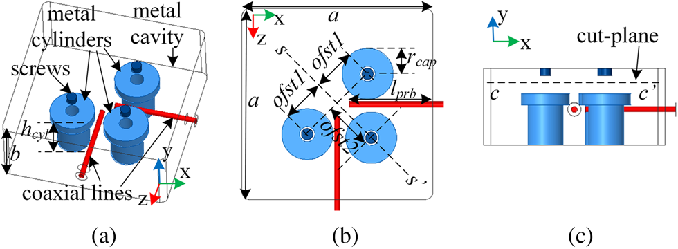
The perspective, top, and side views of the proposed quintuple-mode filter are shown in Figs 1(a), 1(b), and 1(c), respectively. Similar to [Reference Hameed, Xiao, Najam, Qiu and Hameed15], this filter is also realized with a rectangular waveguide cavity. The base-length of the cavity (parameter a) is about λ o/2 while the height of the cavity (parameter b) is kept slightly less than λ o/4, where λ o refers to the wavelength taken at the center frequency. Three off-centered mushroom-shaped perturbation cylinders along with three screws from the top-wall are employed in the cavity. The inner conductors of the coaxial lines are extended into the rectangular cavity from two perpendicular side walls to serve as input and output probes. The two ports are positioned under the caps of mushroom-shaped cylinders. Two of the three perturbation cylinders are shifted away from the symmetrical plane s–s′ in the opposite direction with an offset distance of ofst1, while the third cylinder is shifted away from the origin on the symmetrical plane s–s′ with an offset distance of ofst2. The three perturbation cylinders along with the two input/output probes are responsible for excitation of the five resonant modes. The three perturbation cylinders largely contribute to excite the first three resonant modes; while the cylinders in combination with the two feeding probes, excite the remaining two modes.
Structure of the proposed filter. (a) Perspective view. (b) Top view. (c) Side view with cut-plane used for field observation.

Analysis and design
The proposed filter is analyzed and designed based on the mechanism reported in [Reference Hameed, Xiao and Qiu13] and [Reference Hameed, Xiao, Najam, Qiu and Hameed15], where one and two mushroom-shaped cylinders were used to excite three and four resonant modes, respectively. The mechanism has been extended to employ three off-centered mushroom-shaped cylinders along with the two perpendicular coupling probes, for excitation of five resonant modes in a rectangular cavity. An additional quasi-TM11− mode has been excited by employing the third mushroom-shaped cylinder.
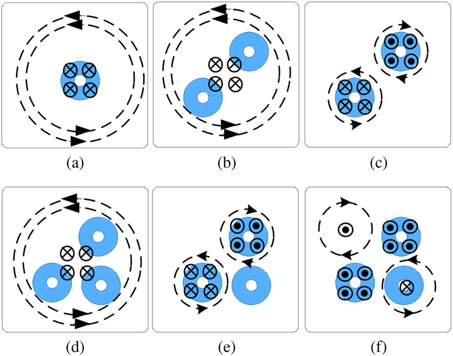
A detailed analysis on how the elements (mushroom-shaped cylinders and coaxial probes) of the resonator contribute to the excitation of each single mode is presented in Fig. 2. The dotted lines show the directions of the magnetic field lines, while the solid lines coming out of the plane or going into the plane represent directions of the electric field lines. One (Fig. 2(a)), and two mushroom-shaped cylinders (Figs 2(b) and 2(c)), in triple- and quadruple-mode filters, contribute to one and two quasi-TM modes, respectively. The remaining two resonant modes in both the cases are excited by perpendicularly placed coaxial probes. Similarly, three quasi-TM modes are excited by three off-centered mushroom-shaped cylinders in the proposed quintuple-mode filter, as clearly depicted in Figs 2(d), 2(e), and 2(f). The last two resonant modes of the proposed quintuple-mode filter are also contributed by the two perpendicular probes, which are also believed to be quasi-TM modes.
Electromagnetic field distributions of the quasi TM-modes excited in a rectangular cavity, loaded with different number of perturbation cylinders. (a) One cylinder. (b), (c) Two cylinders. (d)–(f) Three cylinders.

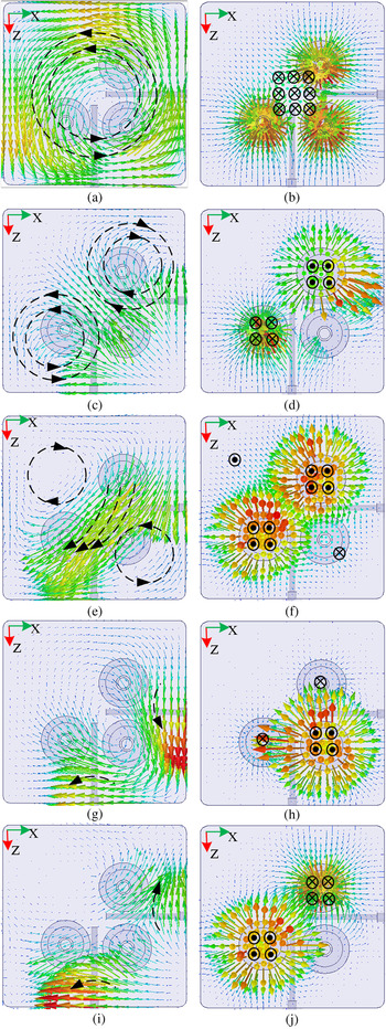
The analysis presented in Fig. 2 is vindicated by examining electromagnetic field distributions of the resonant modes, as displayed in Fig. 3. It can be checked that in these modes, their magnetic fields all have dominant transversal components, with respect to the y-axis. However, their electric fields are not transversally dominant. It is clear that in the gap between the mushroom-shaped cylinder and the side wall, the electric fields are vertically dominant, i.e., the y-components are much larger than the transversal ones. Hence, all these modes are quasi-TM modes, and are different from transverse electromagnetic (TEM) modes. TEM modes usually exist in coaxial resonators. Both their electric fields and magnetic fields have transversal components only. When there is a gap at the end of the inner cylinder of a coaxial resonator, like the mushroom-shaped cylinder used here, the fields in the resonator are disturbed, and the resonant modes are no longer strict TEM modes, instead, they are more like quasi-TM modes. Figure 1(c) shows the cut-plane c–c′ which is perpendicular to the y-axis, and is used for magnetic and electric field observation. The magnetic and electric field distributions of the quasi-TM01 mode are displayed in Figs 3(a) and 3(b), respectively. The magnetic field distributions show circular orientations which are transversal with respect to the cut-plane c–c′, while the electric field distributions are vertically dominant and are going into the plane. Figures 3(c) and 3(d) show the magnetic and the electric field distributions of the quasi-TM11+ mode, and Figs 3(e) and 3(f) show the magnetic and the electric field distributions of the quasi-TM11− mode, respectively. It is clearly seen from these figures that the magnetic field lines are transversal to the plane, while electric field lines are perpendicular (either going in or coming out) to the plane. Hence, the first three resonant modes constitute of quasi-TM01 mode and a pair of degenerate quasi-TM11+ and quasi-TM11− modes. Similarly, after observing the magnetic and electric field distributions from the cut-plane c–c′, the remaining two resonant modes are named as quasi-TM mode-4 and quasi-TM mode-5, as clearly depicted in Figs 3(g)–3(j).
Field distributions of the five resonant modes. (a), (b) H- and E-field distributions of quasi-TM01 mode, respectively. (c), (d) H- and E-field distributions of quasi-TM11+ mode, respectively. (e), (f) H- and E-field distribution of quasi-TM11− mode, respectively. (g), (h) H- and E-field distribution of quasi-TM mode-4, respectively. (i), (j) H- and E-field distribution of quasi-TM mode-5, respectively.

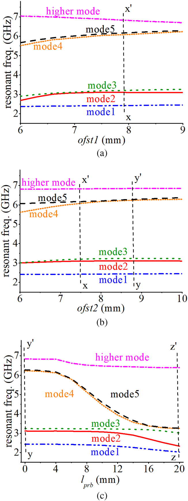
The mode-chart comprising resonant frequencies of the first five resonant modes along with the lowest higher-order mode graphed against different parameters of the filter is shown in Fig. 4. Figure 4(a) shows the variation in offset shift parameter ofst1 from 6 to 9 mm, while fixing ofst2 = 7.5 mm. At around ofst1 = 7 mm, the two degenerate modes (mode-2 and mode-3) are merged into each other. As the value of the ofst1 increases beyond 7 mm, the two modes start separating until an optimum value (line x–x′) is reached. Similarly in Fig. 4(b), the optimum value (line y–y′) of the second offset shift parameter ofst2 can be determined by varying its value from 6 to 10 mm while keeping the already determined optimum value of ofst1 fixed at line x–x′. Insertion of the two coaxial line probes along with the perturbation cylinders brings the mode-4 and mode-5 into the passband to realize the quintuple-mode filter, as shown in Fig. 4(c). The length of the probes (parameter l prb) is increased starting from 0 mm until it reaches its optimum value represented by line z–z′.
Mode-chart comprising resonant frequencies of the first six resonant modes against different parameters of the filter. (a) Offset shift parameter ofst1. (b) Offset shift parameter ofst2. (c) Length of coupling probes l prb.

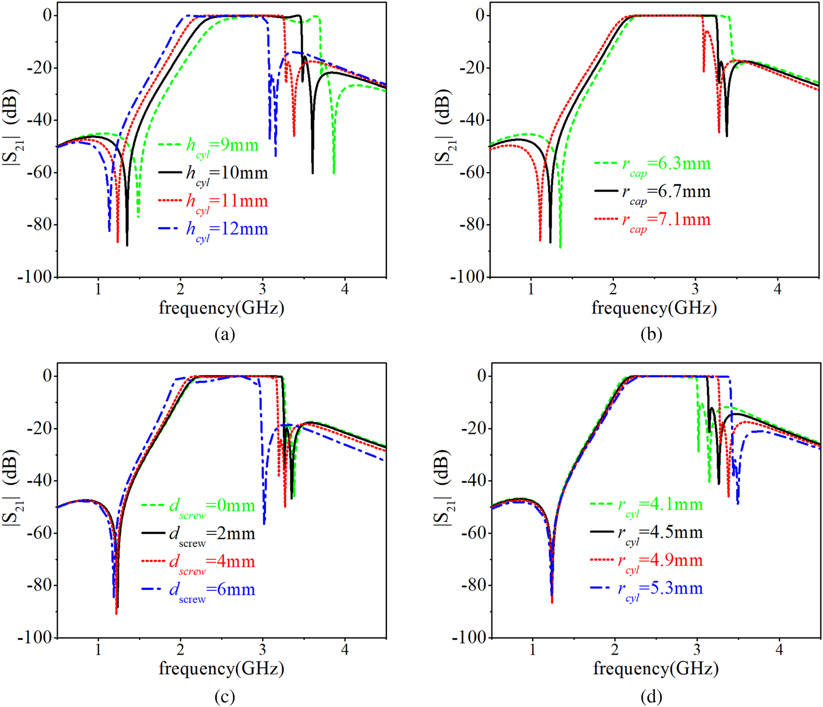
The tuning of a filter is required to make a design flexible. In the proposed quintuple-mode filter, the perturbation is largely obtained by the off-centered mushroom-shaped cylinders, placed in the rectangular cavity. The proposed resonator can be roughly modeled as a coaxial line type section with a rectangular outer metallic wall. One end of the resonators is shorted and the other end is loaded with capacitors, formed by the gap between the cap of the mushroom-shaped cylinders and the top wall of the cavity. The capacitance is affected by the area of the mushroom-shaped cylinder cap, and its distance from the top of the cavity. It can also be tuned by the screw, as shown in Fig. 5. The passband, the bandwidth, and the position of transmission zeros can be tuned by the parametric variation of height of the cylinders (h cyl), radius of the caps (r cap), depth of the screws (d screw), and radius of the cylinders (r cyl), as clearly displayed in Figs 5(a)–5(d), respectively. Increase in the capacitance eventually decreases the resonant frequencies of the five resonant modes resulting in the reduction of cavity size to retain a particular frequency.
Tuning obtained by parametric variation. (a) h cyl, (b) r cap, (c) d screw, (d) r cyl.

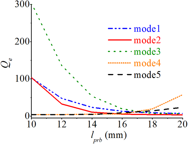
The external quality factor (Q e) of the five resonant modes is graphed against l prb in Fig. 6. For the lower values of l prb, the value of Q e for the first three quasi-TM modes is very high which represent their weak coupling with the input and output coupling probes. When the value of l prb increases beyond 15 mm, the Q e of all the five resonant modes attain stability and remain under 60. The value of Q e for the first five resonant modes is Q e1 = 7.25, Q e2 = 3.74, Q e3 = 6.7, Q e4 = 57.59, and Q e5 = 23.76. The unloaded quality factors for the same modes are 4568, 2861, 4530, 5361, and 5793 respectively.
External quality factor Q e against varying l prb.

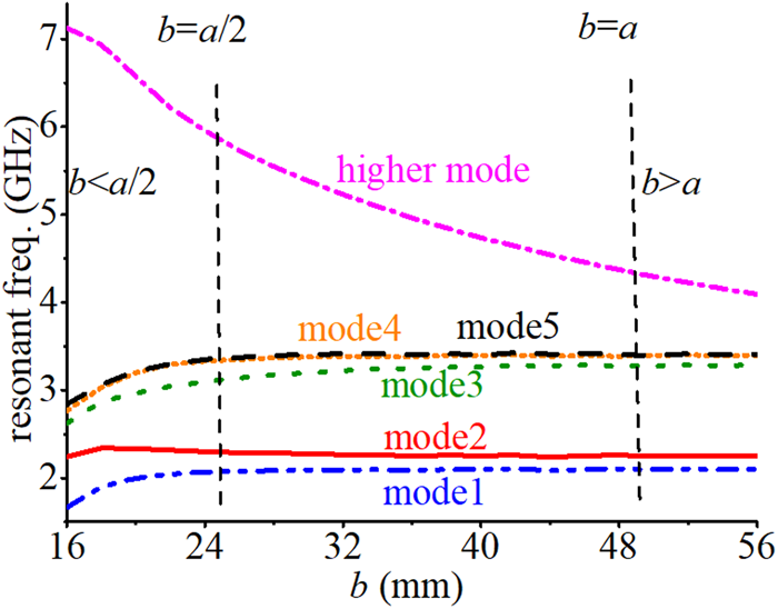
Finally, the height of the waveguide cavity b is exploited to improve the out-of-band rejection by restricting the lowest higher order mode to the higher frequencies, as clearly depicted in Fig. 7. For b > a, the lowest higher-order mode moves very close to the passband, hence providing narrow out-of-band rejection; while for b < a, the higher mode can be pushed away from the passband to achieve a wider out-of-band rejection. Figure 7 shows how a cavity size can be critical in achieving the desired results. Along with the b, mushroom shape of the perturbation cylinders is also crucial in lowering down the resonant frequencies, which in return reduces the overall cavity size [Reference Hameed, Xiao and Qiu13].
Mode-chart comprising resonant frequencies against height of the waveguide cavity b.

Five transmission zeros are generated at lower and upper stopbands of the filter. Two transmission zeros on lower and two transmission zeros on upper stopband are emerged due to source to load coupling provided by the two perpendicular coupling probes, while the remaining one on the upper stopband is emerged by the two orthogonal quasi-TM11+ and quasi-TM11− modes (in other words inclusion of third perturbation cylinder which contribute to excite quasi-TM11− mode), which provide two equal in magnitude but opposite in direction transmission paths, hence canceling each other to generate a transmission zero. Two transmission zeros are located at lower while the other three are located at upper stopband of the filter, which help in improving the selectivity and out-of-band rejection of the filter.
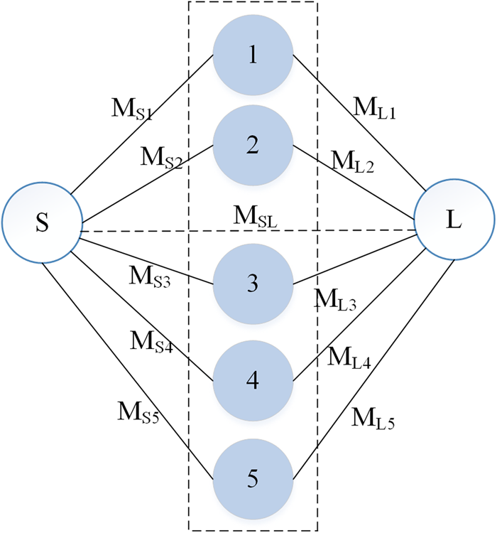
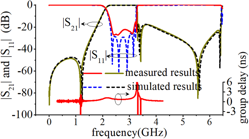
The coupling scheme used in the proposed quintuple-mode filter is fully transversal, where all the five resonant modes are excited in a single cavity. All the resonant modes are coupled directly with the source and the load and there is also a weak coupling present between the source and the load, as clearly shown in Fig. 8. The emergence of five resonant modes (poles) and five transmission zeros in the results (Fig. 9) fully support the coupling topology presented in Fig. 8.
Coupling scheme of the proposed quintuple-mode filter.

Simulated and measured results of reflection and transmission coefficients of the quintuple-mode filter.

The EM simulator Ansoft HFSS is used to design, simulate, and optimize the filter structure. Optimized dimensions of the filter are a = 50, b = 21, ofst1 = 7.9, ofst2 = 8.85, l prb = 20, h cyl = 11, r cyl = 4.9, and r cap = 6.7 (all in mm). The simulated results show that the stopband rejection level is better than 47 dB on the lower side of the passband below 1.2 GHz while it is better than 18 dB on the upper side of the passband from 3.3 to 6.3 GHz, with return loss better than 20 dB as shown in Fig. 9. The simulated insertion loss of the filter is observed less than 0.03 dB.
Experimental results
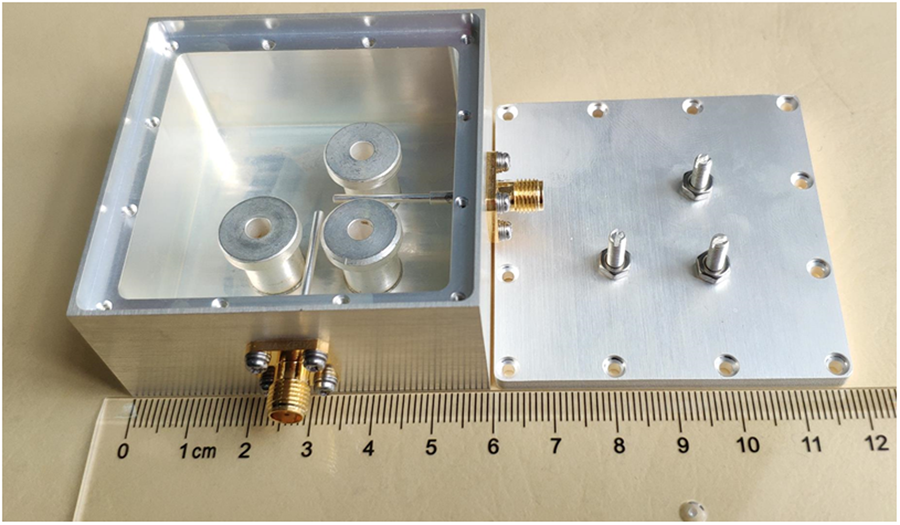
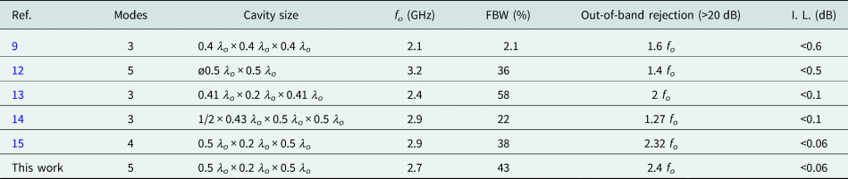
The filter is designed at 2.68 GHz with 43% wide FBW. Figure 9 shows that the simulated and measured S-parameters of the filter agree well with a small deviation, probably caused by losses of the material used and tolerance in the fabrication of the cavity, cylinders, and probes. It was noticed that the tips of the input and output probes were slightly bent away from the mushroom-shaped cylinders, which was believed to be the main cause for the deviation between simulated and measured return loss. The deviation could be minimized by selecting materials with low loss and improving the fabrication process, especially the probes. The measured insertion loss at the center frequency is 0.07 dB and the measured return loss for most of the passband is better than 20 dB. The measured group delay shows considerable linearity along the wider passband of the filter. A prototype filter is fabricated using aluminum to validate the simulated results of the filter, as clearly photographed in Fig. 10. Table 1 compares the proposed filter with the similar studies reported in recent years.
Fabricated quintuple-mode filter.

Comparison among the multi-mode cavity filters

Conclusions and future development
In this paper, it has been shown that the out-of-band rejection can be improved by optimizing the cavity shape and shifting the higher order resonant modes far away from the passband. A quintuple-mode filter employing a rectangular waveguide cavity is presented. Three mushroom-shaped perturbation cylinders along with two perpendicularly inserted coaxial probes are used to excite the five resonant modes. The measured results are in accordance with the simulated results. The measured results of the filter show low insertion loss (<0.07 dB), good return loss (>20 dB), wider FBW (43%), and improved out-of-band rejection (>20 dB at 2.4 f o).
Theoretically, the mechanism can be extended to more than five resonant modes by employing additional perturbation elements, but it will largely depend on the shape of the cavity, and position and height of the additional perturbation elements. Since, all the perturbation cylinders are placed in a single cavity without any walls between them, the excitation and coupling of more than five resonant modes will be a challenging task.
Acknowledgement
This work was partly supported by the National Natural Science Foundation of China under project number 61771304.
 Musab Hameed was born in Pakistan in 1988. He received his Bachelor's and Master's degrees from the National University of Computer & Emerging Sciences (NUCES-FAST), Pakistan in 2010 and 2013, respectively. He is currently pursuing his Ph.D. degree in Electronic Engineering from Shanghai Jiao Tong University (SJTU), China. His research interests include microwave circuit design, filters, and antennas.
 Gaobiao Xiao received his B.S. degree from the Huazhong University of Science and Technology, Wuhan, China in 1988, M.S. degree from the National University of Defense Technology, Changsha, China in 1991, and Ph.D. degree from Chiba University, Chiba, Japan in 2002. He worked in Hunan University, Changsha, China from 1991 to 1997. Since April 2004, he has been a faculty member in the Department of Electronic Engineering, Shanghai Jiao Tong University, Shanghai, China. His research interests are numerical methods in electro-magnetic fields, coupled thermo-electromagnetic analysis, microwave filter designs, fiber-optic filter designs, phased arrays, and inverse scattering problems.
 Lina Qiu was born in Sichuan, China in 1993. She received her B.S. degree from the Huazhong University of Science and Technology, Wuhan, China in 2016. She is currently pursuing her Ph.D. degree in Shanghai Jiaotong University, Shanghai, China. Her current research interests include microwave circuit design, frequency selected surface (FSS), and meta-surface.
 Tayyab Hameed was born in Pakistan in 1992. He has received his bachelor's and master's degrees in electrical engineering from the Federal Urdu University of Arts Science & Technology, Islamabad and Centre for Advanced Studies in Engineering (CASE), Islamabad in 2014 and 2019, respectively. His research interests include microwave filter design, antenna design, and signal processing.