
I. INTRODUCTION—THE OSCAR-MISSION
The emerging class of organic-based photovoltaics—ranging from fully organic solar cells to hybrid organic–inorganic perovskite solar cells—are presented here as a potentially disruptive technology for solar energy generation in space applications, predominantly due to their champion power-to-mass ratio.Reference Kaltenbrunner, White, Glowacki, Sekitani, Someya, Sariciftci and Bauer1 Furthermore, the inherent flexibility of the thin organic layers provides a way of transporting solar cells more densely packed as cargo. Lastly, a concluding asset can be found in their printability. Printing technology could therefore provide a safe, fast pathway for local organic solar cell production, eliminating the immediate need of new shipments from Earth. All these benefits are in contrast with the rigid inorganic solar cell technology (e.g., Si, GaAs, etc.), which has been the main aerospace technology to date.
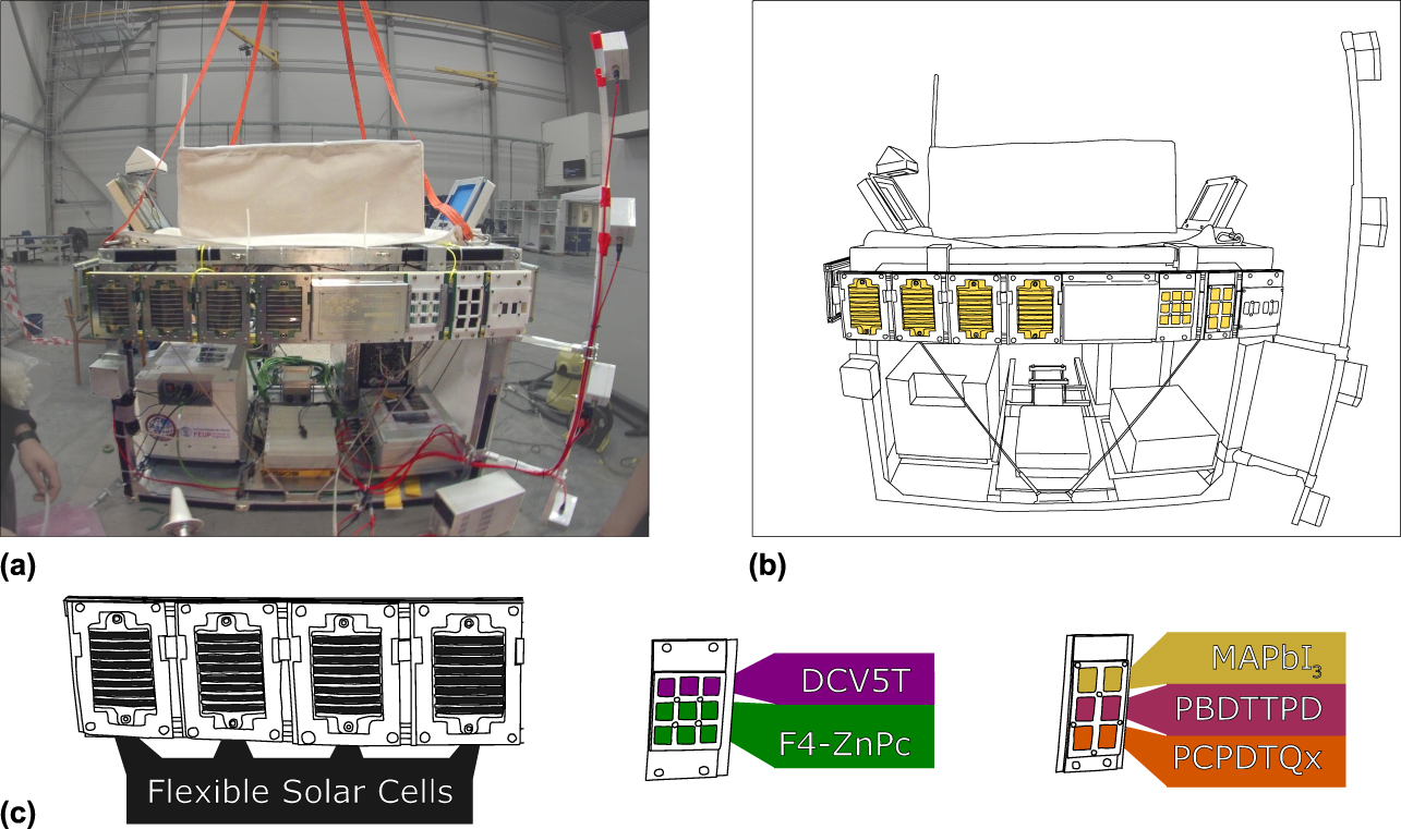
The very recent OSCAR project (Optical Sensors based on CARbon-materials) aimed to explore the use of novel generation carbon-based (i.e., polymer:fullerene, small molecule:fullerene, perovskite, diamond) solar cells/optical sensors for (aero)space applications. This has been achieved through the in situ investigation of devices’ performance during a stratospheric balloon flight in October 2016 (Fig. 1) in combination with ex situ lab experiments.
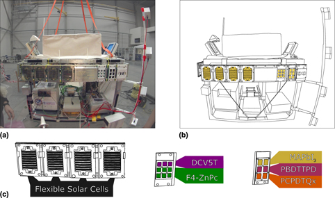
(a) One face of the payload gondola which contained, i.e., the OSCAR experiment. (b) Line trace of the gondola, clearly showing the solar cell sample slots. (c) Allocation of solar cell technologies to the sample slots. Bulk heterojunction organic solar cells are labeled with donor name only and consist, respectively, of DCV5T:C60 (purple), F4-ZnPc:C60 (green), PBDTTPD:PC71BM (cyan), and PCPDTQx(2F):PC71BM (orange) devices.

OSCAR flew on a 30,000 m3 Helium propelled stratospheric balloon in the 23rd cycle of the REXUS/BEXUS program, launched from the Esrange Space Center (SSC) in Kiruna (Sweden). The balloon’s payload consisted of a gondola with outside dimensions of 1160 × 1160 × 780 mm (l × b × h). The OSCAR contribution herein consisted of 4 measurement panels, each with a mix of solar cell types for testing in the upper stratosphere’s near-space environment. Each 1140 × 170 mm panel is made of aluminum strut profiles, spans the gondola’s full width and is mounted to one of the gondola’s sides with rubber bumpers to reduce vibrations, shocks, and create electrical isolation (see Fig. 1). For a clear close-up view on the electrical contacts to the solar cells, the authors refer to Fig. S1 in the Supplementary Material.
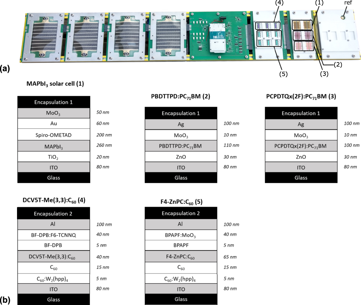
The concept of the in-flight experiment was to allocate various types of organic-based solar cells on modular panels together with measurement electronics and monitor their behavior. Each measurement panel carried 64 solar cells. To gain insight into the performance of commercially available OPV modules, flexible solar cell demonstrators were purchased from InfinityPV (Jyllinge, Denmark). As a comparison with more state-of-the-art systems, lab-scale samples were chosen. Polymer-based PBDTTPD:PC71BM and PCPDTQx(2F):PC71BM devices were prepared at Hasselt University and IMO (Diepenbeek, Belgium)/IMEC (Leuven, Belgium).Reference Pirotte, Kesters, Verstappen, Govaerts, Manca, Lutsen, Vanderzande and Maes2,Reference Verstappen, Kesters, Vanormelingen, Heintges, Drijkoningen, Vangerven, Marin, Koudjina, Champagne, Manca, Lutsen, Vanderzande and Maes3 Since small molecule systems are also gaining more interest, vacuum-processed F4-ZnPc:C60 and DCV5T:C60 solar cells were provided by IAPP (TU Dresden, Germany).Reference Widmer, Tietze, Leo and Riede4,Reference Moench, Friederich, Holzmueller, Rutkowski, Benduhn, Strunk, Koerner, Vandewal, Czyrska-Filemonowicz, Wenzel and Leo5 To finalize the solar cell flight matrix, the standard perovskite solar cell (MAPbI3) was selected and prepared at IMEC. This brings us to a concluding selection of 4 commercial solar cell modules from infinityPV, 36 vacuum-processed small molecule solar cells acquired from IAPP (TU Dresden, Germany), 16 polymer solar cells prepared at Hasselt University, and 8 perovskite solar cells purchased from IMEC. Allocation on the measurement panel and its individual solar cell configuration is shown in Fig. 2. The flexible, commercially bought InfinityPV solar cells have a calculated power-to-mass ratio around 0.6 mW/g (including the metal connectors). The glass substrate-based solar cell power-to-mass ratios are calculated based on their maximum power point (MPP) and weight and provide power-to-mass values around 10 mW/g. For calculation details, the reader is referred to Supplementary Material Sec. 2. Note that the power-to-mass values for the glass substrate-based solar cells include the weight of the glass substrate and can subsequently be increased ever further when going to low weight substrates.
(a) Measurement panel for the OSCAR stratospheric balloon flight with flexible InfinityPV solar cells on the left, the measurement system box at the center, and the other types of tested solar cells—numbered from 1 to 5—at the right. The most right-hand module was added for samples which fall beyond the scope of this communication. It however also carried a Thorlabs FDS100 silicon photodiode used to assess the intensity of incident light. (b) Solar cell configuration for the various types of organic-based solar cells tested with the corresponding numbering of 1–5.

As shown in Fig. 2, the vacuum-processed devices (corresponding with numbers 4 and 5) differ in the encapsulation method and material. These differences arise both due to the device layout and the equipment at hand. For the in-house devices, a glass encapsulation was glued to seal the device. In these cases, DELO-KATIOBOND® LP686 was used as adhesive, as it is known to withstand temperatures down to −40 °C. However, pressure resistance of the adhesive was not specified and therefore was tested with an in-house setup (results are shown in the ex situ experiment part).
The launch campaign (1–10 October 2016) was very successful, i.e., reached a total flight time of more than 5 h, including a floating phase of 2.7 h at an altitude of 32.2 km. The exploratory in-flight experiments performed in this near-space environment, above the cloud deck, on the presented set of organic-based solar cells show that they can operate in the given conditions and therefore confirm that these novel technologies can be potentially interesting for future space applications. In the last paragraph of this contribution, a summary is provided of the obtained in-flight results. A more detailed description of the obtained in-flight results is provided elsewhere.Reference Cardinaletti, Vangerven, Nagels, Cornelissen, Schreurs, Hruby, Vodnik, Devisscher, Kesters, D’Haen, Franquet, Spampinato, Conard, Maes, Deferme and Manca6,Reference Cardinaletti7 The central part of this contribution describes in detail the followed stability assessment methodology, consisting of combined in-flight and lab experiments, and the various technical aspects of the developed measurement set-up. The technical complexity of space-related stability assessment is emphasized by the variety of discussed relevant test parameters and procedures. This information can be helpful for follow-up missions and/or stability assessments. Since no ISOS-type of standard stability tests are yet available for studying and assessing extra-terrestrial degradation, the presented methodology can be considered as a pioneering one, leaving lots of room for further improvements.
II. IN-FLIGHT MEASUREMENT METHODOLOGY
Since in-flight testing in this environment is not evident, an appropriate and reliable integrated methodology needed to be developed covering various aspects, ranging from data acquisition to data transfer. How these various issues have been addressed will be briefly described in this section. More detailed technical information is available in the Supplementary Material.
The measurement panels were interconnected via Ethernet and powered by a central hub (referred to as the “master-box”). An Arduino Due-based measurement board was developed to apply voltages and measure currents to create I–V curves for all solar cell technologies on board. These boards were thereby kept above the minimum operating temperature of their components through active heating to safeguard reliable operation. It was furthermore possible to follow the performance of the solar cells in situ during flight by means of an Ethernet communication system between the balloon and the ground station, which allowed reading out the I–V curves of all samples in real time.
Since the balloon was outfitted with a myriad of on board emitted radio frequent signals from communication systems (other experiments, flight systems, etc.), electrical isolation was foreseen to ensure immunity from electrical noise.
The ground station was implemented in LabVIEW software (National Instruments, Zaventem, Belgium) to achieve a clear and functional user interface with minimal time investment, while making sure that the I–V characteristics could be followed throughout the balloon flight. Up to 4 solar cell’s current I–V curves could be displayed on-screen at the same time. In this way, connection failures as well as rotational position relative to the sun could be derived from the curves instantaneously. This position could be confirmed by photodiodes that were equipped on each solar cell panel with the purpose of tracking the relative position of each panel with respect to the sun.
Theoretical measuring resolutions are directly correlated with the measurement range. For the flexible, commercially bought InfinityPV solar cells, this was in the order of magnitude of 2 mV and 200 μA. For MAPbI3, PBDTTPD:PC71BM, and DCV5T:C60, it was 300 μV and 5 μA, respectively, 200 μV and 2.5 μA for PCPDTQx(2F):PC71BM, F4-ZnPc:C60 and the silicon reference diode. Six measuring circuits were working in parallel on 64 solar cell devices. A full panel sweep took about 20 s including data transfer to the ground station.
By monitoring a solar cell’s I sc, V oc, and MPP during flight, conclusions can be drawn on its state of degradation. The presented in situ measurements can however not directly be compared to those taken in a controlled laboratory environment considering that the BEXUS flight circumstances do not match the preferred measuring circumstances. Preferred circumstances for measuring a solar cell’s I sc, V oc, and MPP are as follows: a constant sample temperature of 25 °C, AM1.5 normalized spectrum light exposure with fixed angle and intensity, and four-probe separate current and voltage measurements to remove contact resistance effects. Temperature, pressure, light intensity, light spectrum, and light angle of incidence were already expected to fluctuate prior to the experiment. Emphasis was therefore put on sample count, material variety, and measurement sampling rate. Actual measuring circumstances differed vastly. Air temperature was measured at system level and is believed to further differ significantly at cell level because of the combination of nonuniform solar radiation reaching the gondola and low ambient pressure induced absence of convection. Pressure furthermore also varied over several orders of magnitude. Light distribution varied both by incident angle due to the flight trajectory as well as by intensity owing to the rotational movement of the gondola around its vertical axis.
Bringing all these unknown variables into account, a decisive strategy was put forward to measure as quantitatively as possible and at the same time, only draws qualitative conclusions from the resulting data. For instance, the measurement setup was not equipped with four-probe measurements but instead applied voltage and measured current in a single circuit path. Measures undertaken to further quantify results and support qualitative analysis on the other hand range from (i) taking incident light measurements by combining I–V measurements from a Thorlabs FDS100 silicon photodiode (Thorlabs, Newton, New Jersey) with its precise correlation of light intensity with the characteristic I–V curve, over (ii) measuring temperature and rotation on gondola level, to (iii) equipping the measurement boards with reference resistors of which the measured value can be used to monitor measurement stability with changing measuring environment. Each of these measures further strengthen the foundation on which qualitative conclusions were drawn; however, they again had their own downfalls. These were respectively: (i) an error margin on the readout of all I–V characteristics with order of magnitude 10% which was also used to take measurements from the silicon photodiode, (ii) a nonuniform measurement time base amongst measuring units, and (iii) no way to separate the measurement environment’s primary effect on the stability of measurements from its secondary effect on the reference resistor values themselves. The reader is referred to Supplementary Material Sec. 7 for details on determination of I–V measurement system error margin. Ultimately, many research opportunities remain for performing in-flight analysis on organic-based solar cell technologies for aerospace applications. With OSCAR, a substantial number of samples representing a variety of materials were analyzed for space environment-induced degradation from a high level approach.
III. EX SITU ENVIRONMENT TESTS
Due to its exposure to extreme conditions during the BEXUS balloon flight, it is a necessity to develop both mechanical structures and electronic equipment that can withstand these harsh conditions, both to warrant accurate measurements and to vouch for the safety of the entire setup. In the following, we investigate whether ex situ environmental testing can predict structural/electronic behavior of the system’s components and may provide a tool to improve stability of those components (solar cell stability, electronic functionality, structural integrity, etc.). To this end, dedicated climate chambers were used to simulate flight behavior. Important contributions to the extreme flight environment are pressure, temperature, vibrations, and radiation. Each of these will be discussed individually. Other possible perturbations such as aerosol influence and incident angle of light were omitted from the ex situ test matrix as they lie beyond the scope of the OSCAR project. An overview of other interesting and important parameters for aerospace application testing can be found in the outlook in Table I.
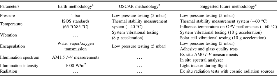
Overview of standard methodology used on earth, the methodology used by OSCAR, and the suggested methodology based on the OSCAR experiment.

b Values based on previous BEXUS flights within the constraints of the project.
c Values based on previous BEXUS flights and the International Standard Atmosphere model.
A. Pressure testing
Since the flight path of the OSCAR experiment passes through the atmosphere at an altitude of 32 km, the experienced pressure by the gondola will be lower than the standard pressure of 1 bar which is experienced at sea level. Based on previous BEXUS flights and the International Standard Atmosphere model, it is known that electronic and mechanical components can experience down to 10 mbar pressure around this altitude, which will influence heat transfer by convection, expansion of insulation material, and stress the mechanical setup of the gondola. In addition, low pressure could have an effect on the packaging of the solar cells.
To investigate the influence of pressure on the set of investigated solar cells and on the components of the measurement set-up, pressure testing was executed in a glass bell which functioned as a vacuum chamber. In terms of a reliable in-flight measurement set-up operating at the low pressures encountered in aerospace environments, it has to be emphasized that the following two parameters are of utmost importance: on one hand, the heat transfer in the system needs to be investigated under low pressure due to the lack of heat convection; on the other hand, the expansion of the used materials needs to be investigated to prevent structural damage to components.
In a first series of pressure tests, the effect of low pressure on the measurement system was investigated. The goal is to identify the possible failures mentioned and solve them accordingly. The outcome of this first series of pressure tests was that the structural stability of the equipment box was guaranteed down to 5 mbar, with no mechanical or electronic component breakdown. This test furthermore proved that, through pre-flight verification, one can assure safe heat transfer without overheating systems and that careful choice of insulation materials can inhibit risks regarding expansion of said materials. It is therefore concluded that pressure testing needs to be performed pre-flight to ensure a successful experiment in aerospace environments.
As a second test, solar cell devices of all types were placed under the glass bell, investigating the quality of the encapsulation when exposed to decreasing pressure. It was shown that the solar cell devices with the tested in-house encapsulation failed when exposed to rapid declining pressure values by means of ejection or breaking the top glass encapsulation from the sample and therefore was identified as a possible weak point for the real flight experiment, whereas the encapsulation of the vacuum-processed small molecule devices resisted the pressure drops. This test already indicates that the encapsulation method/material will be important for aerospace conditions, as differences can be observed between different methods and materials. It is suggested that a possible failing mechanism in low pressure is related to the quality of the glue since MAPbI3, PBDTTPD:PC71BM, PCPDTQx(2F):PC71BM, DCV5T:C60, and F4-ZnPc:C60 all used glass-on-glass encapsulation but differed in glue composition. The MAPbI3, PBDTTPD:PC71BM, and PCPDTQx(2F):PC71BM encapsulations were sealed with DELO-KATIOBOND® LP686, whereas the small molecule-based devices used XNR 5592 adhesive (Nagase ChemteX, Osaka, Japan).Reference Siegmund, Mischok, Benduhn, Zeikq, Ullbrich, Nehm, Böhm, Spoltore, Fröb, Körner, Leo and Vandewal8 Another possibility might be related to the quality of the top glass encapsulation. Investigation on the glass quality is however outside of the scope of this paper but should be accounted for in future aerospace testing.
B. Temperature testing
Since the flight takes place in the stratospheric region of the atmosphere, temperatures can drop down to −60 °C. BEXUS23, for instance, reached a minimum air temperature of −56.8 °C (Fig. S3). The effect of low temperature on the I–V characteristics and performance of organic-based solar cells could thus be investigated during flight. The tests needed for such a balloon flight are 2-fold: the electronic components that are in charge for measuring the I–V curves should be able to withstand extreme low temperatures and the solar cell technology chosen should be able to survive these temperatures.
For the ex situ pre-flight testing, the electronic components were tested at low temperature conditions to safeguard their functionality. The main goal here is to achieve accurate and stable operation of the components at low temperatures and strike a balance between power consumption and controlled operating temperature. The power consumption of the heating element that heats the electronic circuitry should be kept as low as possible due to battery constraints. This is tested by placing the measurement box inside a thermal climate chamber while monitoring the temperature inside and outside the measurement box (see the Supplementary Material). It was stated as a requirement by REXUS/BEXUS experts that the measurement setup should still function down to temperatures of −40 °C over the duration of a stratospheric balloon flight (estimated 2–5 h based on previous stratospheric balloon flights).
The conclusion from this test is that additional heating near the electronic components can be executed with decently low power supply, which in that way can guarantee the operational functionality of the electronic circuitry needed to measure I–V curves of the solar cell array.
As mentioned, solar cell testing at low temperature is also desired to ensure performance of the chosen material systems. This requires dedicated light sources that should be integrated in the thermal climate chamber. This was not feasible at the time of the OSCAR flight. Although the envisaged set of solar cells have not been measured as a function of temperature, this was not a major drawback for the understanding of the obtained in-flight results since the effect of temperature on the performance of organic-based solar cells is sufficiently reported in the literature. Nevertheless, toward a solid methodology to assess the stability of organic solar cells for aerospace conditions, it is recommended to execute appropriate thermal climate chamber testing on organic solar cells pre-flight to ensure operation during aerospace conditions.
C. Vibrational testing
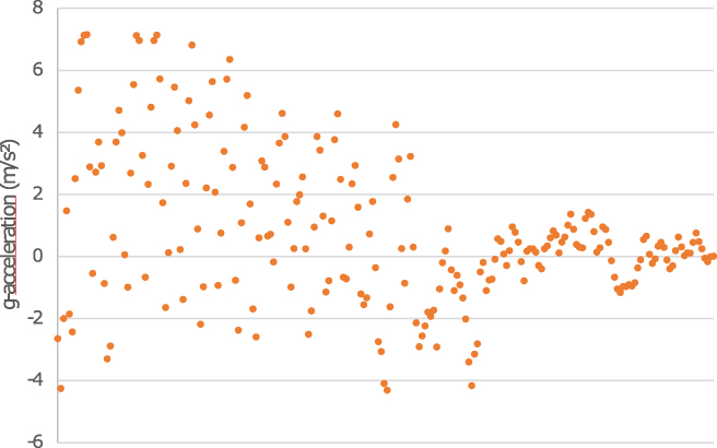
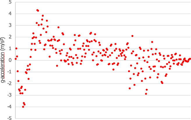
Since aerospace testing requires a launch of a system (balloon, satellite, and rocket), it is also recommended to investigate the effect of high acceleration forces on the system. There are two critical moments during the balloon flight where the system is subjugated to high acceleration and vibrational motion. During the actual launch, high g-forces and vibrations are expected due to the uplifting by the balloon. During the descend phase, the system will crash back onto land. Although the setup is equipped with a parachute, accelerations up to a few g’s can be expected during this time. It is therefore required to ensure stability of the mechanical structure to prevent breakdown of components. Therefore, a mock-up frame was assembled. On this frame, a measurement panel was attached, in the same way as it would be during flight take-off. Subsequently, the frame was dropped from different heights with Vernier 3-axis (accuracy = ±0.05 g) accelerometers attached to it to measure the g-values it was experiencing. First of all, an upright drop acceleration test is performed. As one might expect the system is thereby kept horizontal (upright) and subsequently dropped. During the test, the system is exposed to 8 g accelerations, as is shown in Fig. 3. This acceleration is close to what can be expected during the balloon launch/landing, where accelerations can be found between 5 and 10 g accelerations in the worst case.
Upright drop-acceleration test result. The x-axis represents the short timescale when the setup hits the ground.

After the drop test, the system was optically investigated for signs of structural damage and electronic failure. After multiple drop tests, the system still showed no signs of inferior performance, which indicates that the whole system is able to survive the high accelerations that it might be subjugated to when positioned with the bottom to the ground.
Since it cannot be guaranteed that the balloon will land on the bottom side, a secondary experiment was performed where the mock-up frame was dropped on the side. This test is called the sideways drop acceleration test. The results are given in Fig. 4. Although lower values have been tested, it is expected that 4 g accelerations should safeguard to the integrity of the mechanical setup for the landing.
Sideways drop-acceleration test result. The x-axis represents the short timescale when the setup hits the ground.

It can therefore be concluded that it is possible to make decently large solar cell testing matrices without sacrificing the structural integrity of the system. This indicates that even larger matrices might be used which can carry more samples, hence increasing the statistical power of such experiment.
No vibrational tests were executed on a filled solar cell panel. This was due to quantity constraints, as it would require many more devices to test this. It is not expected that vibrations will influence the stability of the solar cells much since all devices were placed in holders with specific dimension to ensure that no movement was possible inside the holder. This was done to prevent contact loss between the spring contacts and the solar cell electrodes. It is however suggested that—when possible—solar cell vibrational testing is performed to investigate the stability of the spring contact/electrode interface.
D. Radiation
Within the framework of the OSCAR-project no ex situ radiation tests were performed. As mentioned, the electrical insulation was incorporated in each measurement box, which protected the electronic circuitry from radiation. Testing of the solar cell technologies proved more difficult, as it requires specialized light sources, which unfortunately were unavailable. But since radiation is a key environmental stress parameter for space applications, in the following, a discussion is provided on the effect of radiation on organic-based solar cells.
As a general rule, it can be stated that high energy radiation has a detrimental effect on soft matter, including organic-based blends used in the field of OPV. High energy radiation is known to cleave side-chains and induce radicals, which in turn can induce side reactions in the film. This will have a detrimental effect on the device performance, as the morphology and electronic properties of the active layer will be influenced.
To date, little investigation is pursued on the influence of high energy radiation on organic-based solar cells. Under normal earth circumstances at sea level, a larger part of the earth has an incident solar spectrum varying between AM1 (tropical equator regions) and AM2 (high altitude, high latitude regions), where most testing is performed under AM1.5 conditions, since the main solar industry is located in these regions (USA, Europe, China, Japan, India, etc.). Therefore most solar cell experiments are performed under AM1.5 conditions. AM1.5 corresponds with a black body spectrum with the addition of absorption of certain spectral regions due to atmospheric light absorption (e.g., UV light will be absorbed in the ozone layer, inducing a lower UV contribution in the AM1.5 spectrum compared to the black body spectrum). When performing investigations on matter outside of the earth’s atmosphere, matter will be subjugated to an AM0 spectrum, which corresponds with black body radiation around 5800 K. AM0 radiation will therefore be a harsher environment for organic-based solar cells, as the high energetic radiation will not be filtered out by the Earth’s atmosphere. Additionally, high energy particles like protons and electrons are prone to pass through space due to solar eruptions, which can induce further radical formation and degradation.
Few papers have investigated the effect of radiation on organic-based PV performance. It is generally known that exposure of these materials to X-rays can cause degradation of the photoactive layer morphology or can make incisions in the sidechains of the polymers and destroy conjugated systems. Guo et al. investigated the influence of switching to an AM0 illumination source as incident light spectrum.Reference Guo, Brandt, Andreev, Metwalli, Wang, Perlich and Müler-Buschbaum9 This spectrum coincides with the incident light spectrum in space, without interfering absorption of the earth’s atmospheric layers. It was shown that both open circuit voltage V oc and short circuit current density I sc rise with increasing intensity, while the fill factor and efficiency decrease, which is in agreement with observations under AM1.5 illumination.Reference Riedel, Parisi, Dyakonov, Lutsen, Vanderzande and Hummelen10 The influence of temperature during AM0 illumination was shown to decrease the V oc with increasing temperature, as is in-line with AM1.5 observations.Reference Park, Noh, Lee, Kim and Lee11 The same is true for I sc, which increases with temperature due to thermal-assisted hopping of charge carriers. Therefore, it can be concluded that AM0 incident light will induce the same changes to OPV operation as compared to AM1.5. However, it is expected that lifetime will suffer due to the higher energy radiation. To date, no lifetime studies comparison between AM0 and AM1.5 were made, as previous experiments were executed with an AM0 source on rather short timescale (2000 s), whereas lifetime testing usually envelops multiple hours.
Kumar et al. investigated the influence of X-rays on organic-based PV devices.Reference Kumar, Rosen, Devine and Yang12,Reference Kumar, Devine, Mayberry, Lei, Li and Yang13 It was shown that in the case of P3HT:PC61BM (1:1 ratio), no electronic or structural defects are observed in the photoactive layer. Moreover, it is expected that radical regeneration decreases when the conjugation in an organic material increases, as was reported by VoevodskiiReference Voevodskii and Molin14 in 1962, which is in accordance with the previous statement on structural defects in P3HT:PC61BM blends. It was shown that in the case of a P3HT:PC61BM (1:1) device, the loss in I sc is independent of the dose rate, as tests were performed before and after radiation at 0.3 Mrad (SiO2) X-ray exposure. The V oc however seems to drop and it is suggested that this is caused by charge accumulation at the electrode interfaces, which increases the built-in potential of the devices. It is possible to decrease this V oc drop due to smart engineering of the device stack. It was shown that the V oc decrease is smaller when a ZnO/Al electrode is used instead of Ca/Al. Recent radiation hardness studies on perovskite-based solar cells were performed by Lang et al. using high-energy proton irradiation and demonstrated a higher robustness compared to crystalline silicon. Additionally promising for space applications is that the irradiated perovskites exhibited self-healing properties.Reference Lang, Nickel, Bundesmann, Seidel, Denker, Albrecht, Brus, Rappich, Rech, Landi and Neitzert15
If it is desirable to fine-tune organic-based photovoltaic technology to compete with the present inorganic space solar cell modules, one needs to be able to compare their outputs in the given environment. Attempts have already been made to see the effect of long exposure outdoor conditions for both technologies. Kettle et al. investigated the behavior of both OPV and Si-based PV when exposed in outdoor conditions, both for good and bad weather, following the ISOS-O-1 protocol for outdoor lifetime testing.Reference Reese, Gevorgyan, Jørgensen, Bundgaard, Kurtz, Ginley, Olson, Lloyd, Morvillo, Katz, Elschner, Haillant, Currier, Shrotriya, Hermenau, Riede, Kirov, Trimmel, Rath, Inganäs, Zhang, Andersson, Tvingstedt, Lira-Cantu, Laird, McGuiness, Gowrisanker, Pannone, Xiao, Hauch, Steim, DeLongchamp, Rösch, Hoppe, Espinosa, Urbina, Yaman-Uzunoglu, Bonekamp, van Breemen, Girotto, Voroshazi and Krebs16,Reference Bristow and Kettle17 It was shown that solar cell devices in general seem to heat up when exposed to longer illumination periods (timescale ∼ day). Furthermore, the c-Si PV devices seem the heat up a bit more, which is suggested to happen due to their broader absorption band, since silicon absorbs up to 1100 nm. For organic solar cells, it is known that long-term exposure to high temperatures can lead to significant changes in the morphology of the photoactive layer and therefore also in the photovoltaic performance.Reference Cardinaletti, Kesters, Bertho, Conings, Piersimoni, D’Haen, Lutsen, Nesladek, Van Mele, Van Assche, Vandewal, Salleo, Vanderzande, Maes and Manca18,Reference Bertho, Haeldermans, Swinnen, Moons, Martens, Lutsen, Vanderzande, Manca, Senes and Bonfiglio19
In conclusion, it can be stated that protection of the electronic circuitry of the measurement box can be incorporated by means of electric shielding. Ideally, this could be tested by radiating the shielded measurement box with a cosmic radiation source. The same observation can be made for the organic-based solar cells. Literature is available to give a global idea of high energy radiation and its effect on OPV. However, this field is relatively unexplored and should be thoroughly investigated if one wants to increase the understanding of cosmic radiation effects on organic-based solar cells. It is preferable to test the influence of high energy radiation on the devices to investigate their performance and stability when exposed to aerospace conditions. This requires a designated radiation source to simulate cosmic radiation.
It was stated at the beginning of this section that the most important influences for a stratospheric experiment include pressure, temperature, vibrations, and radiation. The experiments discussed in the ex situ part showed that most of the environmental influences in space can be accounted for with the intensive use of specialized climate chambers. It was shown that the electronic measurement setup can be fully tested ex situ against individual contributions (vibrations, temperature, and pressure). Light spectrum and intensity do not need to be taken into account for electronic stability due to shielding and inhibition of exposure.
IV. IN SITU FLIGHT RESULTS
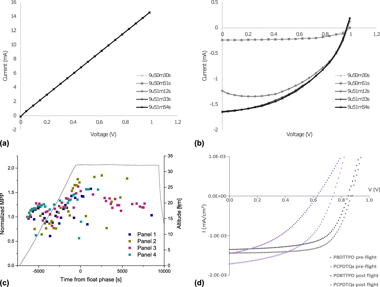
With the presented OSCAR mission and in-flight measurement methodology, the OSCAR team was able to perform a first of its kind in-flight analysis of different organic-based solar cell technologies for aerospace applications. In this paragraph, a summary is provided of the obtained in-flight results. A more detailed description of the obtained in-flight results is provided elsewhere.Reference Cardinaletti, Vangerven, Nagels, Cornelissen, Schreurs, Hruby, Vodnik, Devisscher, Kesters, D’Haen, Franquet, Spampinato, Conard, Maes, Deferme and Manca6,Reference Cardinaletti7 To prove the stability of our measurement system in a dual manner, Figs. 5(a) and 5(b) show 5 consecutive IV measurements both of a solar cell (here PBDTTPD:PC71BM is shown as an illustration) under changing light exposure together with IV measurements of the internal reference resistor from the specific dedicated measuring circuit of the investigated solar cell at the same points in time. The sweeps displayed correspond to the point in time when the balloon has reached its coldest point during flight. As seen from the solar cell I–V measurements, two are in the dark state, one is under changing light and the last two are under full sunlight exposure. Both dark state sweeps overlap, as well as both full exposure sweeps. From the reference resistor I–V sweeps, on the other hand, complete overlap is observed of normal, straight lines coming from consecutive measurements as is expected for a plain resistive component. The stability of reference resistor measurements at coincident points in time suggests the reliability of their accompanied organic-based solar cell I–V measurements.
(a) IV measurement showing 5 consecutive voltage sweeps of the reference resistor during flight at the coldest point during flight. (b) IV measurement showing 5 consecutive voltage sweeps of a PBDTTPD:PC71BM solar cell during flight at a float altitude of 32 km. The margin of error has an order of magnitude of 10%. The calculations on the margin of error can be found in Supplementary Material Sec. 7. (c) The normalized MPP in function of time and altitude for PBDTTPD:PC71BM devices for all four sides of the gondola. (d) IV curves for PBDTTPD:PC71BM (black) and PCPDTQx(2F):PC71BM (purple) devices before (open circles) and after (full circles) the stratospheric balloon flight.

Figure 5(c) tracks the MPP over time for all 4 solar cell panels (i.e., all sides) during the BEXUS balloon flight for the PDBTTPD:PC71BM samples. It shows that the MPP values globally increase with increasing altitude. Direct correlation of the observed evolution of the MPP to temperature and the expected positive temperature coefficient behaviorReference Bristow and Kettle17,Reference Zhang, Qiao, Shen and Wang20 is more complex, as outside temperatures fluctuate between −50 and 10 °C during ascension of the balloon and light conditions vary as function of altitude. However, once the balloon passes the lowest temperature point and the temperature starts to increase again, MPP values are rising equally. Therefore a positive temperature coefficient behavior might still take place during flight, but a more in-depth investigation is required to confirm a direct correlation between the temperature increase and the rising MPP values. It is hypothesized that the increase of MPP with increasing altitude can also be partly attributed to the absence of clouds at float altitude, leading to an obstruction-free pathway for the sunlight to reach the solar cell samples. This leads to higher illumination intensities at higher altitudes. Tracking of the MPP also enables insights into the rotational motion of the gondola, as the panel which faces the sun will have the highest MPP value at a given time for a given solar cell layout.
Furthermore, the IV characteristics of the solar cells were measured both before and after flight, to investigate if any degradation occurs during flight. Figure 5(d) shows the IV curves before and after flight for PBDTTPD:PC71BM and PCPDTQx(2F):PC71BM devices. In both cases, a drop in both V oc and fill factor can be observed, thus implying a degradation pathway for the solar cells during the exposure to extreme conditions during flight. The analysis of the degradation pathway is however not straightforward since conditions differ greatly from standard solar cell measurement conditions at Earth. Pressure, temperature, encapsulation quality, light spectrum, and light intensity can all influence solar cell performance and these parameters might interfere with each other. The importance of ex situ performance testing is therefore important to gain additional insights in solar cell performance and degradation pathways since the information of an in situ experiment alone will not provide enough insights on these topics.
As mentioned before, the ex situ vacuum testing of the encapsulation quality showed that the DELO-KATIOBOND® LP686/glass encapsulation failed during rapid de-pressuring of the glass bell. This phenomenon was also observed during the OSCAR balloon flight.Reference Cardinaletti, Vangerven, Nagels, Cornelissen, Schreurs, Hruby, Vodnik, Devisscher, Kesters, D’Haen, Franquet, Spampinato, Conard, Maes, Deferme and Manca6 The MAPbI3, PBDTTPD:PC71BM, and PCPDTQx(2F):PC71BM devices did indeed exhibit a decreasing number of working solar cells. Particularly, in the case of the MAPbI3 devices, the encapsulation glass even broke open during flight, confirming that the encapsulation method of those devices was inferior to the other methods. The IAPP encapsulation of the F4-ZnPc:C60 and DCV5T:C60 devices proved to be much more effective, as was also the case for the commercial InfinityPV solar cells, with a drop-out far less than the DELO-KATIOBOND® LP686/glass encapsulated samples during the complete process (from purchase until touch-down BEXUS flight). This proves that encapsulation for OPV devices designed for operation under extreme conditions is available, but the encapsulation adhesive/method needs to be investigated beforehand to ensure the survivability of the cells during operation. Based on these findings, it can therefore be stated that the encapsulation material and method strategy play an important role for OPV stability when exposed to stratospheric environments.
V. CONCLUSIONS AND OUTLOOK
The OSCAR mission provided a first in-flight analysis of different organic-based solar cell technologies for aerospace applications. To assess the stability of organic-based solar cells in aerospace conditions, a methodology has been presented based on a combination of in-flight and ex situ lab experiments. For follow-up missions and/or aerospace related stability testing, various lessons can be learned from the experiences encountered during the OSCAR-project.
During ex situ climate chamber testing, it was proven that the electronic equipment requirements for a large-scale multiplatform solar cell testing matrix for stratospheric applications can be verified by means of dedicated climate chambers that simulate aerospace environments. The electronic system was guaranteed to function at ambient temperatures down to −40 °C and at pressures below 10 mbar, whereas ideal testing would be performed at −60 °C as it is the coldest temperature that can be expected during the transition of the atmosphere to altitudes of 32 km (during the passing of the tropopause). Due to the complication of needing a specifically designed AM0 illumination source for testing solar cell performance in aerospace conditions, an ex situ investigation of said cells proved more difficult. It was shown however that the encapsulation material plays an important role in the operation of the solar cell in stratospheric environmental conditions and that adhesive and/or glass quality may be responsible for device failure. Pressure chamber testing confirmed the crucial role of the encapsulation, proving that the encapsulation quality can vary depending on adhesive supplier, glass specifications, and device layout.
A custom measuring setup was implemented to take in situ solar cell performance measurements on the OSCAR stratospheric balloon flight. A high level approach was utilized for in situ testing. By monitoring each solar cell’s I sc, V oc, and MPP during flight, it was possible to draw conclusions on their state of degradation. Adequate encapsulation proved to be a decisive factor in respect of organic solar cell life expectancy in space-like environments. Fill factors were furthermore studied in relation to temperature and a direct correlation was found in agreement to previous measurements. In general, it was demonstrated that all types of organic solar cells can survive an exposure window of a few hours in stratospheric near-space conditions.
Although shown that individual environment aspects can be simulated, the challenge remains to create ex situ climate chambers capable of simulating all environmental influences at the same time. This would allow a more in-depth comparison between in situ flight data and ex situ lab tests and would allow better insights into OPV behavior in said conditions.
The OSCAR flight proved the possibility to measure arrays of organic-based solar cells in an accurate and rapid way under stratospheric conditions. Due to the near-space environment, this is a first step toward deployment in real space conditions. It is shown that ex situ environment testing allows for pre-elimination of possible electronical and mechanical errors and allows for accurate verification of the components. The solar cells themselves proved to have stable performance during flight, whereas the bottleneck for aerospace applications is allocated to encapsulation issues, providing a rapid breakdown in the solar cell.
Stability assessment of organic-based solar cells for aerospace applications is characterized by a multitude of relevant test parameters and procedures and therefore requires appropriate measurement setups and protocols. Since no standardized stability tests are yet available for studying and assessing extra-terrestrial degradation for organic-based solar cells, the presented methodology can be considered as a pioneering one, leaving lots of room for further improvements. As an outlook toward future methodologies for stability assessments of organic-based solar cells for space applications, Table I proposes a list of the most important parameters and corresponding reliability tests that need to be taken into account. It gives an overview of the performed methodology and the preferred methodology for future stratospheric balloon flight experiments. This table can be used as a guideline to which parameters should be tested and specific values for stratospheric OPV testing.
When extrapolating this guiding table toward real space conditions, it should be noted that these values are subject to change since conditions will become even harsher. Aerospace environments encompass a broad range of temperatures, pressures, and light intensities. Therefore, it is recommended that for atmospheric altitude testing, preliminary investigation of the targeted environment is undertaken to determine the minimal values for the parameters given in Table I and that the testing values are changed accordingly to compensate for the temperature, pressure, and light intensity at the given altitude. For real space conditions, an approximation for parameter values can be chosen based on Qualification and Quality Requirements for Space Solar Cells AIAA S-111A-2014. Pressure testing is suggested to be performed at 10−5 torr while the temperature testing ranges from −175 to 140 °C. Radiation hardness testing will also become an important factor due to the absence of any shielding from cosmic radiation by the Earth’s magnetic field, which leads to an increase in exposure to high energetic radiation.
The OSCAR mission within the REXUS/BEXUS program provided the unique opportunity for a pioneering experiment to test organic-based solar cells in stratospheric conditions. As an exploration effort, its scope was deliberately kept as broad as possible with a broad range of device technologies and large number of sample cells. A logical follow-up now would be to physically scale down to a more manageable extent. The thereby freed up space would allow for a more comprehensive temperature stabilizing system for the measuring circuit, usage of more accurate 4 wire connections for both solar cell readout as well as calibration efforts (e.g., reference resistors), deployment of a fully independent light spectrometer and, possibly, module level temperature measurements. The combination of this as-followed methodology, which combines in-flight and ex situ tests, together with the lessons learned and proposed outlook can open the path for future investigations on the performance and long term stability of organic-based solar cells for aerospace applications.
Supplementary Material
To view supplementary material for this article, please visit https://doi.org/10.1557/jmr.2018.156.
ACKNOWLEDGMENTS
The OSCAR project was developed in the framework of the REXUS/BEXUS program. This program is a joint collaborative agreement between the German Aerospace Center (DLR) and the Swedish National Space Board (SNSB), where the Swedish share of the balloon payload is made available for European university student experiments with collaboration of the European Space Agency (ESA). Other partners include EuroLaunch, a collaboration between the Esrange Space Center (SSC), which is the launching facility in Kiruna (Sweden) and the Mobile Rocket Base (MORABA) of DLR. Experts of all involved parties are provided throughout the project for technical support. The authors deeply thank M. De Roeve, R. Lempens, J. Soogen, K. Daniëls, J. Boutsen, and J. Mertens for the technical help, and K. Wouters and M.A. Beynaerts for their support during testing. IMEC vzw is acknowledged for their availability with sample supplies and encapsulation. For the small molecule-based devices thanks are due to TU/Dresden. For the polymer-based devices, the authors would like to thank the DSOS research group at Hasselt University. The authors would like to thank Hasselt University for additional financial support.